EP0834764A2 - Adaptateur pour un dispositif d'affichage pour une présentation utilisant un rétroprojecteur - Google Patents
Adaptateur pour un dispositif d'affichage pour une présentation utilisant un rétroprojecteur Download PDFInfo
- Publication number
- EP0834764A2 EP0834764A2 EP97307092A EP97307092A EP0834764A2 EP 0834764 A2 EP0834764 A2 EP 0834764A2 EP 97307092 A EP97307092 A EP 97307092A EP 97307092 A EP97307092 A EP 97307092A EP 0834764 A2 EP0834764 A2 EP 0834764A2
- Authority
- EP
- European Patent Office
- Prior art keywords
- display
- sleeves
- adapter
- recess
- remote control
- Prior art date
- Legal status (The legal status is an assumption and is not a legal conclusion. Google has not performed a legal analysis and makes no representation as to the accuracy of the status listed.)
- Granted
Links
Images


Classifications
-
- G—PHYSICS
- G03—PHOTOGRAPHY; CINEMATOGRAPHY; ANALOGOUS TECHNIQUES USING WAVES OTHER THAN OPTICAL WAVES; ELECTROGRAPHY; HOLOGRAPHY
- G03B—APPARATUS OR ARRANGEMENTS FOR TAKING PHOTOGRAPHS OR FOR PROJECTING OR VIEWING THEM; APPARATUS OR ARRANGEMENTS EMPLOYING ANALOGOUS TECHNIQUES USING WAVES OTHER THAN OPTICAL WAVES; ACCESSORIES THEREFOR
- G03B21/00—Projectors or projection-type viewers; Accessories therefor
- G03B21/132—Overhead projectors, i.e. capable of projecting hand-writing or drawing during action
-
- H—ELECTRICITY
- H04—ELECTRIC COMMUNICATION TECHNIQUE
- H04N—PICTORIAL COMMUNICATION, e.g. TELEVISION
- H04N21/00—Selective content distribution, e.g. interactive television or video on demand [VOD]
- H04N21/40—Client devices specifically adapted for the reception of or interaction with content, e.g. set-top-box [STB]; Operations thereof
- H04N21/41—Structure of client; Structure of client peripherals
- H04N21/422—Input-only peripherals, i.e. input devices connected to specially adapted client devices, e.g. global positioning system [GPS]
- H04N21/42204—User interfaces specially adapted for controlling a client device through a remote control device; Remote control devices therefor
- H04N21/42206—User interfaces specially adapted for controlling a client device through a remote control device; Remote control devices therefor characterized by hardware details
-
- H—ELECTRICITY
- H04—ELECTRIC COMMUNICATION TECHNIQUE
- H04N—PICTORIAL COMMUNICATION, e.g. TELEVISION
- H04N9/00—Details of colour television systems
- H04N9/12—Picture reproducers
- H04N9/31—Projection devices for colour picture display, e.g. using electronic spatial light modulators [ESLM]
- H04N9/3141—Constructional details thereof
-
- Y—GENERAL TAGGING OF NEW TECHNOLOGICAL DEVELOPMENTS; GENERAL TAGGING OF CROSS-SECTIONAL TECHNOLOGIES SPANNING OVER SEVERAL SECTIONS OF THE IPC; TECHNICAL SUBJECTS COVERED BY FORMER USPC CROSS-REFERENCE ART COLLECTIONS [XRACs] AND DIGESTS
- Y10—TECHNICAL SUBJECTS COVERED BY FORMER USPC
- Y10S—TECHNICAL SUBJECTS COVERED BY FORMER USPC CROSS-REFERENCE ART COLLECTIONS [XRACs] AND DIGESTS
- Y10S248/00—Supports
- Y10S248/917—Video display screen support
Definitions
- This invention relates to display adapters for displays, such as detachable LCD screens from portable computers, to adapt the displays for use with overhead projectors.
- the projector display panels have a flat LCD (liquid crystal display) panel which is transparent and open on both sides to pass light from the projector.
- the panel is framed within an enclosure which houses electronics for interfacing the panel to a computer, such as a laptop.
- the computerized projector display panel rests atop the projector.
- Electronically stored slides are depicted on the LCD panel during the presentation. Light is directed through the transparent LCD panel, projecting the slide content onto the projection screen.
- a presenter can create a more dynamic presentation using video, graphic animation, enhanced colors, programmable slide timing, and sound synchronization.
- the presenter can also control the presentation from a remote location using a remote control device, freeing the presenter to walk away from the projector.
- the user can also edit the slide content and presentation order directly on the computer, without having to prepare new physical slides.
- U.S. Patent No. 5,227,820 to Miyashita et al. describes a shading device for an projector display panel.
- the shading device has two opaque plates that slide outward beyond the periphery of the LCD panel to cover the areas of the projector light surface that are left uncovered by the panel.
- U.S. Patent No. 5,337,103 to Gulick describes an overhead projection display panel having members that fold or slide out to cover unmasked areas of the projector light surface.
- projector display panels require the presenter to carry, in addition to the portable computer, the following separate items: (1) projector screen, (2) remote control device, (3) dongle with IR (infrared) receiver connected to the portable computer, and (4) cable from portable computer to the display panel. If one of these items is forgotten or lost, the presenter may be unable to make a computerized presentation, or at least will not be able take advantage of the remote control capabilities.
- U.S. Patent No. 5,041,965 to Chen describes a laptop computer with a detachable display for use with an overhead projector.
- the display has a detachable cover that is attached when the display is used as a monitor and detached when the display is used as a projector panel.
- a separate projector display panel is not needed, thereby eliminating its cost.
- the presenter only needs to transport the laptop computer, as opposed to a portable computer plus the projector display panel.
- the detachable laptop display has a similar problem in that it does not entirely cover the projector light surface, leaving the unwanted bright spots on the projection screen which can spoil a presentation.
- Another drawback is that the display is placed directly atop the projector light surface. During the presentation, the covered area becomes increasingly hotter and may cause damage to both the laptop display and the projector.
- This invention concerns a display adapter which adapts a display, such as a laptop LCD, to provide a computerized projector display panel.
- the display is physically and electrically connected to the adapter.
- the display adapter has a parallel cable and electronic interfacing circuitry to interface the display with a computer.
- the adapter has an enclosure with a central body and two extendible sleeves slidably mounted to the body.
- the sleeves move between an expanded position and a collapsed position. In the expanded position, the sleeves project outward from the body in opposing directions. In the collapsed position, the sleeves are slid inward relative to the body toward each other to an abutting relationship.
- the enclosure also has two support arms movably mounted to the first and second sleeves, respectively.
- the support arms move between an opened position and a closed position.
- the arms are pivotally mounted to outer ends of the sleeves to swing between the opened and closed positions.
- the adapter is arranged with the sleeves in their expanded position and the arms in their opened position.
- the display is physically and electronically coupled to the adapter.
- the display is supported horizontally by the support arms a safe distance above the projector light surface to prevent overheating.
- the extended sleeves cover one entire side of the projector light surface and the display covers the remaining surface areas. In this manner, the combined assembly blocks are light areas, thereby preventing projection of unwanted bright spots on a projection screen.
- the adapter body has a recess sized to hold a remote control handset, such as an IR device.
- a remote control handset such as an IR device.
- the recess is exposed to permit removal and replacement of the IR device.
- An IR port is formed in the body and exposed when the sleeves are extended to receive IR signals from the IR device.
- the sleeves cover and protect the IR device.
- a view aperture is formed in one or both of the sleeves to permit a view of the recess so that a user can visually confirm the presence or absence of the IR device.
- the display adapter thus integrates into one device all of the components used in conjunction with a portable computer to conduct a computerized overhead projector presentation.
- Fig. 1 is an isometric view of a display adapter for an overhead projector.
- Fig. 1 shows the display adapter in a collapsed position.
- Fig. 2 is an isometric view showing the display adapter in an expanded position.
- Fig. 3 is an isometric, exploded view of the display adapter.
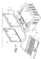
- Fig. 4 is an isometric view of the display adapter being used with a laptop computer to form a computerized presentation display unit.
- Figs. 1 and 2 show a display adapter 20 which adapts a display for use with an overhead projector.
- the adapter 20 physically supports the display above the projector light surface and electronically interfaces the display with a separate computing unit.
- the display adapter 20 has an enclosure 22 with a central body 24 and two extendible sleeves 26, 28 slidably mounted to the body 24.
- the sleeves 26, 28 move between a collapsed position shown in Fig. 1 and an expanded position shown in Fig. 2.
- the sleeves are slid inward relative to the body 24 to an abutting relationship to cover at least part, and preferably all, of the body 24.
- the sleeves 26, 28 are extended outward from the body 24 in opposing directions along a central, elongated axis 30 to expose the body 24.
- the enclosure 22 has a first support arm 32 movably mounted to the first sleeve 26 and a second support arm 34 movably mounted to the second sleeve 28.
- the arms 32, 34 move between a closed position and an open position.
- the support arms 32, 34 are pivotally mounted to outer ends of the first and second sleeves 26, 28 to pivot about pivot axes 36, 38, respectively.
- the pivot axes 36, 38 are transverse, and preferably perpendicular, to the central elongated axis 30. In this manner, the support arms 32, 34 alternately fold together against the sleeves in the closed position (Fig. 1) or unfold outward through 90° angles to the opened position (Fig. 2). Stops 40, 42 are formed on arms 32, 34, respectively, to prevent over rotation past an approximately 90° angle. In the opened position, the support arms 32, 34 are approximately perpendicular to the axis 30.
- the arms might be formed to slide or telescope from the ends of the sleeves in a direction perpendicular to the central axis 30.
- the arms can be detachably connected to the sleeves in which the sleeves are detached and stored in the enclosure in the closed position and attached to extend perpendicularly from the sleeves in the opened position.
- the arms might also be operably mounted to the display.
- the enclosure body 24 has a recess 50 formed in the upper surface (Fig. 2).
- the recess 50 is sized to hold a remote control handset 52, such as a remote control IR (Infrared) device, a remote control RF (radio frequency) device, or the like.
- the recess 50 is exposed when the sleeves 26, 28 are in the expanded position (Fig. 2). This permits a presenter to remove the IR handset 52 and use it for the presentation. Afterward, the presenter returns the IR handset 52 to the recess 50 and slides the sleeves 26, 28 back over the recess and IR handset to the collapsed position (Fig. 1). In this manner, the IR handset 52 is protected within the enclosure 22 during transportation.
- a view opening 54 is formed in at least one sleeve to provide a view of the recess 50. This allows the user to visually verify that the IR device 52 is safely housed within the enclosure 22 when the first and second sleeves are in the collapsed position.
- the view opening is formed partly in both sleeves, which together form an approximately annular view hole; but, other aperture constructions are possible.
- the adapter enclosure 22 has two mounting apertures 56 and 58 which physically receive the mounting posts on the display. The posts are inserted into the apertures 56 and 58 when the display is supported by the adapter, as is illustrated in Fig. 4.
- the enclosure 22 also has an electrical connector 60 to connect to a compatible connector on the display. In the illustrated implementation, the connector 60 is positioned in the first sleeve 26 to accommodate a detachable laptop display, as is described below in more detail with reference to Fig. 4.
- Fig. 3 shows the adapter 20 in a disassembled condition.
- the adapter 20 has a printed circuit board (PCB) 62 housed within the body 24.
- the connector 60, PCB 62, and a parallel conductor cable 64 provide electronic interfacing circuitry to interface the display with a computing unit.
- the PCB 62 supports a remote signal receiving port to receive remotely transmitted signals (e.g., IR, RF, etc.) from the remote control handset 52.
- the PCB 62 has an IR receiver port to receive IR signals generated by the IR handset 52.
- An IR cap or lens 66 which is formed of a material transparent to IR signals, is assembled as part of the body 24.
- the IR handset 52 transmits IR signals to the adapter 20, which converts the IR signals to digital signals that are passed over the conductor 64 to the computer.
- a fan 68 may optionally be mounted within the body 24 to blow air out through an air grate 70 (Fig. 2) to circulate air beside the adapter body and between the support arms 32, 34.
- This air circulation helps cool the display and projector light surface.
- the enclosure design may facilitate sufficient circulation without a fan because the enclosure, in the illustrated implementation, supports only three sides of the display, leaving a fourth side open. Moreover, the support arms maintain the display at a spaced distance from the projector light surface. Accordingly, air circulation through the opened fourth side and in the gap between the display and projector light surface may be sufficient to maintain a safe operating temperature.
- the adapter may also be equipped with a power cord to supply power to the fan, or configured to receive power from the portable computer.
- Fig. 4 shows the adapter 20 being used with a laptop computer 80 to form a computerized projector display for an overhead projector 100.
- the computer 80 has a CPU unit 82 and a detachable display 84, such as an LCD screen, which can be detached from the CPU 82.
- the display 84 has a detachable backlight cover 86 which is removed to convert the monitor into a projector panel.
- U.S. Patent No. 5,041,965 to Chen describes a suitable laptop computer with detachable display. This patent is hereby incorporated by reference.
- the presenter To set up the adapter 20 for a presentation, the presenter extends the sleeves 26, 28 to the expanded position and folds out the support arms 32, 34 to the opened position. The adapter 20 is then placed over one entire side of the projector light surface. Next, the display 84 is detached from the laptop CPU 82 and the back cover 86 is removed. The display 84 has posts 88 and 90 which are inserted respectively into mounting apertures 56 and 58 of the adapter 20 to physically mount the display onto the adapter. During this physical engagement, the electrical connector 60 on the adapter 20 mates with a compatible connector on the display 84 (not shown, but located beside the post 88) to provide an electronic coupling between the adapter 20 and the display 84.
- the display is then tilted 90° as indicated by arrow 92 to a horizontal orientation to rest on the support arms 32, 34.
- the support arms support the display 84 a spaced distance above a light surface 102 of the overhead projector 100 to prevent overheating.
- the extended sleeves 26, 28 cover one entire side area of the projector light surface 102 adjacent to the display.
- the adapter 20 and display 84 cover the entire projector light surface to prevent formation of peripheral bright spots on the projection screen.
- the presenter couples the adapter cable 64 to the parallel port of the laptop CPU 82.
- the presenter removes the IR handset 52 from the recess 50 and uses it to control the presentation. More specifically, the presenter directs the IR handset 52 toward the IR receiver port on the PCB 62 housed within body 24 behind IR lens 66.
- the IR receiver converts the optical signals to digital signals, which are then transmitted over cable 64 to the computer CPU 82. These digital signals contain control information for managing the presentation software executing on the computer.
- the presenter decouples the cable 64 from the laptop CPU 82 and replaces the IR handset 52 in the adapter recess 50.
- the presenter removes the display 84 from the adapter and reattaches it to the computer CPU 82.
- the presenter folds the support arms 32, 34 back along side the adapter 20 to the closed position and slides the sleeves 26, 28 back over the body 24 to the collapsed position. The compact adapter is then ready for easy portability with the laptop computer.
- Fig. 4 shows a laptop computer with detachable display
- the adapter can be used with other types of displays.
- other forms of computers can be substituted for the laptop, such as notebook and sub-notebook computers.
- the adapter is advantageous because it incorporates all of the functions and items needed for a computerized overhead projection presentation into a light weight and highly compactible device which is easy to transport. For mobile people, compact size is beneficial for travel convenience and integration of components is beneficial from a standpoint of remembering all of the items used in the presentation.
- the display adapter can be used with a laptop computer, an item normally employed in computerized presentations.
- the adapter integrates the physical support mechanism which supports the laptop display a safe distance above the projector light surface (i.e., to prevent overheating) with the electronics and IR components used to operate the computerized presentation. Additionally, since the adapter does not have its own LCD screen, the adapter is comparatively less expensive compared to traditional computerized projector display panels.
Landscapes
- Physics & Mathematics (AREA)
- General Physics & Mathematics (AREA)
- Engineering & Computer Science (AREA)
- Human Computer Interaction (AREA)
- Multimedia (AREA)
- Signal Processing (AREA)
- Devices For Indicating Variable Information By Combining Individual Elements (AREA)
- Overhead Projectors And Projection Screens (AREA)
Applications Claiming Priority (2)
| Application Number | Priority Date | Filing Date | Title |
|---|---|---|---|
| US726598 | 1991-07-08 | ||
| US08/726,598 US5823651A (en) | 1996-10-07 | 1996-10-07 | Display adapter for overhead projector presentation |
Publications (3)
| Publication Number | Publication Date |
|---|---|
| EP0834764A2 true EP0834764A2 (fr) | 1998-04-08 |
| EP0834764A3 EP0834764A3 (fr) | 1999-11-17 |
| EP0834764B1 EP0834764B1 (fr) | 2002-05-22 |
Family
ID=24919256
Family Applications (1)
| Application Number | Title | Priority Date | Filing Date |
|---|---|---|---|
| EP97307092A Expired - Lifetime EP0834764B1 (fr) | 1996-10-07 | 1997-09-12 | Adaptateur pour un dispositif d'affichage pour une présentation utilisant un rétroprojecteur |
Country Status (4)
| Country | Link |
|---|---|
| US (1) | US5823651A (fr) |
| EP (1) | EP0834764B1 (fr) |
| JP (1) | JPH10123618A (fr) |
| DE (1) | DE69712697T2 (fr) |
Families Citing this family (15)
| Publication number | Priority date | Publication date | Assignee | Title |
|---|---|---|---|---|
| JP3669413B2 (ja) * | 1999-05-17 | 2005-07-06 | 日本電気株式会社 | 画像表示用アダプタを備えた移動端末と回線品質変化対応方法 |
| AU2001266870A1 (en) | 2000-06-13 | 2001-12-24 | Eddie W. Derryberry | Electronic image projection device |
| US6772265B2 (en) | 2000-12-11 | 2004-08-03 | International Business Machines Corporation | Docking station for a laptop computer |
| JP2003218545A (ja) * | 2002-01-23 | 2003-07-31 | Seiko Epson Corp | 電子機器用外装ケース、この電子機器用外装ケースを備えるプロジェクタ |
| GB2409052B (en) * | 2003-12-12 | 2008-06-18 | Simon Richard Daniel | Cube shaped lamp and projection device for single slide |
| US7958892B2 (en) | 2005-07-29 | 2011-06-14 | Resmed Limited | Air delivery system |
| CN119280587A (zh) | 2006-02-17 | 2025-01-10 | 瑞思迈私人有限公司 | 结合增强治疗法 |
| USD569408S1 (en) * | 2006-08-22 | 2008-05-20 | Hewlett-Packard Development Company, L.P. | Projector |
| US20100214737A1 (en) * | 2007-09-12 | 2010-08-26 | Cheng Yu Huang | Extendable heat-dissipating base set for notebook computers |
| US8323041B2 (en) * | 2011-02-17 | 2012-12-04 | Citizen Finetech Miyota Co., Ltd. | Connectors for connecting a projector module to an application module |
| TWD146660S (zh) * | 2011-07-19 | 2012-04-21 | 宏碁股份有限公司 | 投影機 |
| USD722098S1 (en) * | 2013-10-30 | 2015-02-03 | Casio Keisanki Kabushiki Kaisha | Information display terminal |
| JP1525421S (fr) * | 2013-12-18 | 2018-05-21 | ||
| US9948838B2 (en) * | 2015-02-20 | 2018-04-17 | Freedom Scientific, Inc. | Articulated desktop magnifier |
| US12174675B2 (en) | 2019-11-26 | 2024-12-24 | Hewlett-Packard Development Company, L.P. | Holding devices for computing components |
Family Cites Families (16)
| Publication number | Priority date | Publication date | Assignee | Title |
|---|---|---|---|---|
| US4921343A (en) * | 1985-09-05 | 1990-05-01 | Fuji Photo Film Co., Ltd. | Overhead projector |
| US4728184A (en) * | 1987-05-26 | 1988-03-01 | Buhl Industries, Inc. | Foldable transparency enlarger for overhead projector |
| FI88214C (fi) * | 1987-12-30 | 1993-04-13 | Educatek Oy | Bildkastare |
| JPH063383Y2 (ja) * | 1988-04-28 | 1994-01-26 | 株式会社東芝 | オーバヘッドプロジェクタユニットの脚構造 |
| US4968134A (en) * | 1988-06-29 | 1990-11-06 | Ricoh Company, Ltd. | Overhead projector |
| US4944578A (en) * | 1988-07-21 | 1990-07-31 | Telex Communications | Color graphic imager utilizing a liquid crystal display |
| US5353075A (en) * | 1988-08-17 | 1994-10-04 | In Focus Systems, Inc. | Convertible flat panel display system |
| US5337103A (en) * | 1993-01-06 | 1994-08-09 | In Focus Systems, Inc. | Case for overhead projection display panel |
| US5041965A (en) * | 1990-08-10 | 1991-08-20 | Rever Computer Inc. | Laptop computer with detachable display for overhead projector |
| US5168294A (en) * | 1990-09-07 | 1992-12-01 | Texas Instruments Incorporated | Display demonstration system for providing enlarged projected image of calculator display |
| US5317350A (en) * | 1992-03-19 | 1994-05-31 | Fuji Photo Film Co., Ltd. | Overhead projector |
| US5227820A (en) * | 1992-06-01 | 1993-07-13 | Ctx-Electronics Corporation | Shading device of the LCD projecting plate |
| US5260730A (en) * | 1993-01-25 | 1993-11-09 | Numa Corporation | Optical overhead projector for electronic images |
| US5521660A (en) * | 1994-09-29 | 1996-05-28 | Texas Instruments Inc. | Multimedia field emission device portable projector |
| JPH08262993A (ja) * | 1995-03-03 | 1996-10-11 | Internatl Business Mach Corp <Ibm> | 携帯型情報処理装置及び携帯型情報処理装置用スタンド |
| US5593221A (en) * | 1995-06-27 | 1997-01-14 | Silicon Graphics, Inc. | Overhead projector for flat panel display capability |
-
1996
- 1996-10-07 US US08/726,598 patent/US5823651A/en not_active Expired - Fee Related
-
1997
- 1997-09-12 DE DE69712697T patent/DE69712697T2/de not_active Expired - Fee Related
- 1997-09-12 EP EP97307092A patent/EP0834764B1/fr not_active Expired - Lifetime
- 1997-10-02 JP JP9269458A patent/JPH10123618A/ja active Pending
Also Published As
| Publication number | Publication date |
|---|---|
| JPH10123618A (ja) | 1998-05-15 |
| US5823651A (en) | 1998-10-20 |
| DE69712697T2 (de) | 2003-03-06 |
| EP0834764B1 (fr) | 2002-05-22 |
| EP0834764A3 (fr) | 1999-11-17 |
| DE69712697D1 (de) | 2002-06-27 |
Similar Documents
| Publication | Publication Date | Title |
|---|---|---|
| US5823651A (en) | Display adapter for overhead projector presentation | |
| US5876105A (en) | Notebook size LCD projector | |
| US5856819A (en) | Bi-directional presentation display | |
| US5986634A (en) | Display/monitor with orientation dependent rotatable image | |
| US5847748A (en) | Multimedia projection system | |
| JP3184730B2 (ja) | 携帯型情報処理装置 | |
| US5630659A (en) | Compact high resolution light valve projector | |
| US6262884B1 (en) | Portable computer inherently carried with overhead projection device | |
| CA2188720A1 (fr) | Projecteur pliant a ecran a cristaux liquides | |
| US5231434A (en) | Overhead projector for LCD panel | |
| AU668642B2 (en) | Case for overhead projection display panel | |
| US5302985A (en) | Overhead projector for LCD panel | |
| CN1214128A (zh) | 小型集成的液晶显示器(lcd)投影仪 | |
| US6980253B1 (en) | Prompter | |
| JPH10108111A (ja) | デュアルユースビデオディスプレイシステム | |
| JPH0643421A (ja) | プロジェクタ | |
| JPH07255027A (ja) | スクリーン収納式投写型表示装置 | |
| JP3315320B2 (ja) | 液晶プロジェクタ | |
| CN220917028U (zh) | 一种展示板 | |
| KR100192295B1 (ko) | 오에이취피겸용 액정 프로젝터 | |
| JP3121046U (ja) | プロジェクタ | |
| JP3526253B2 (ja) | コンポジット式液晶プロジェクタ | |
| JP4296871B2 (ja) | 投影装置 | |
| JPH0419888Y2 (fr) | ||
| JPH05274058A (ja) | 電子機器システム |
Legal Events
| Date | Code | Title | Description |
|---|---|---|---|
| PUAI | Public reference made under article 153(3) epc to a published international application that has entered the european phase |
Free format text: ORIGINAL CODE: 0009012 |
|
| AK | Designated contracting states |
Kind code of ref document: A2 Designated state(s): DE FR GB |
|
| AX | Request for extension of the european patent |
Free format text: AL;LT;LV;RO;SI |
|
| PUAL | Search report despatched |
Free format text: ORIGINAL CODE: 0009013 |
|
| AK | Designated contracting states |
Kind code of ref document: A3 Designated state(s): AT BE CH DE DK ES FI FR GB GR IE IT LI LU MC NL PT SE |
|
| AX | Request for extension of the european patent |
Free format text: AL;LT;LV;RO;SI |
|
| 17P | Request for examination filed |
Effective date: 20000117 |
|
| 17Q | First examination report despatched |
Effective date: 20000420 |
|
| AKX | Designation fees paid |
Free format text: DE FR GB |
|
| RAP1 | Party data changed (applicant data changed or rights of an application transferred) |
Owner name: HEWLETT-PACKARD COMPANY, A DELAWARE CORPORATION |
|
| GRAG | Despatch of communication of intention to grant |
Free format text: ORIGINAL CODE: EPIDOS AGRA |
|
| GRAG | Despatch of communication of intention to grant |
Free format text: ORIGINAL CODE: EPIDOS AGRA |
|
| GRAH | Despatch of communication of intention to grant a patent |
Free format text: ORIGINAL CODE: EPIDOS IGRA |
|
| GRAH | Despatch of communication of intention to grant a patent |
Free format text: ORIGINAL CODE: EPIDOS IGRA |
|
| GRAA | (expected) grant |
Free format text: ORIGINAL CODE: 0009210 |
|
| REG | Reference to a national code |
Ref country code: GB Ref legal event code: FG4D |
|
| REF | Corresponds to: |
Ref document number: 69712697 Country of ref document: DE Date of ref document: 20020627 |
|
| ET | Fr: translation filed | ||
| PLBE | No opposition filed within time limit |
Free format text: ORIGINAL CODE: 0009261 |
|
| STAA | Information on the status of an ep patent application or granted ep patent |
Free format text: STATUS: NO OPPOSITION FILED WITHIN TIME LIMIT |
|
| 26N | No opposition filed |
Effective date: 20030225 |
|
| PGFP | Annual fee paid to national office [announced via postgrant information from national office to epo] |
Ref country code: GB Payment date: 20040908 Year of fee payment: 8 |
|
| PGFP | Annual fee paid to national office [announced via postgrant information from national office to epo] |
Ref country code: FR Payment date: 20040920 Year of fee payment: 8 |
|
| PGFP | Annual fee paid to national office [announced via postgrant information from national office to epo] |
Ref country code: DE Payment date: 20041102 Year of fee payment: 8 |
|
| PG25 | Lapsed in a contracting state [announced via postgrant information from national office to epo] |
Ref country code: GB Free format text: LAPSE BECAUSE OF NON-PAYMENT OF DUE FEES Effective date: 20050912 |
|
| PG25 | Lapsed in a contracting state [announced via postgrant information from national office to epo] |
Ref country code: DE Free format text: LAPSE BECAUSE OF NON-PAYMENT OF DUE FEES Effective date: 20060401 |
|
| GBPC | Gb: european patent ceased through non-payment of renewal fee |
Effective date: 20050912 |
|
| PG25 | Lapsed in a contracting state [announced via postgrant information from national office to epo] |
Ref country code: FR Free format text: LAPSE BECAUSE OF NON-PAYMENT OF DUE FEES Effective date: 20060531 |
|
| REG | Reference to a national code |
Ref country code: FR Ref legal event code: ST Effective date: 20060531 |