EP0835532B1 - Procede pour reduire la resistance interne d'accumulateurs rechargeables - Google Patents
Procede pour reduire la resistance interne d'accumulateurs rechargeables Download PDFInfo
- Publication number
- EP0835532B1 EP0835532B1 EP96914982A EP96914982A EP0835532B1 EP 0835532 B1 EP0835532 B1 EP 0835532B1 EP 96914982 A EP96914982 A EP 96914982A EP 96914982 A EP96914982 A EP 96914982A EP 0835532 B1 EP0835532 B1 EP 0835532B1
- Authority
- EP
- European Patent Office
- Prior art keywords
- rechargeable battery
- power source
- accumulator
- voltage
- cells
- Prior art date
- Legal status (The legal status is an assumption and is not a legal conclusion. Google has not performed a legal analysis and makes no representation as to the accuracy of the status listed.)
- Expired - Lifetime
Links
Images
Classifications
-
- H—ELECTRICITY
- H01—ELECTRIC ELEMENTS
- H01M—PROCESSES OR MEANS, e.g. BATTERIES, FOR THE DIRECT CONVERSION OF CHEMICAL ENERGY INTO ELECTRICAL ENERGY
- H01M6/00—Primary cells; Manufacture thereof
- H01M6/50—Methods or arrangements for servicing or maintenance, e.g. for maintaining operating temperature
- H01M6/5011—Methods or arrangements for servicing or maintenance, e.g. for maintaining operating temperature for several cells simultaneously or successively
-
- H—ELECTRICITY
- H01—ELECTRIC ELEMENTS
- H01M—PROCESSES OR MEANS, e.g. BATTERIES, FOR THE DIRECT CONVERSION OF CHEMICAL ENERGY INTO ELECTRICAL ENERGY
- H01M10/00—Secondary cells; Manufacture thereof
- H01M10/42—Methods or arrangements for servicing or maintenance of secondary cells or secondary half-cells
- H01M10/44—Methods for charging or discharging
-
- H—ELECTRICITY
- H02—GENERATION; CONVERSION OR DISTRIBUTION OF ELECTRIC POWER
- H02J—ELECTRIC POWER NETWORKS; CIRCUIT ARRANGEMENTS OR SYSTEMS FOR SUPPLYING OR DISTRIBUTING ELECTRIC POWER; SYSTEMS FOR STORING ELECTRIC ENERGY
- H02J7/00—Circuit arrangements for charging or discharging batteries or for supplying loads from batteries
- H02J7/875—Charging or discharging for charge maintenance, battery initiation or rejuvenation
-
- H—ELECTRICITY
- H01—ELECTRIC ELEMENTS
- H01M—PROCESSES OR MEANS, e.g. BATTERIES, FOR THE DIRECT CONVERSION OF CHEMICAL ENERGY INTO ELECTRICAL ENERGY
- H01M10/00—Secondary cells; Manufacture thereof
- H01M10/24—Alkaline accumulators
- H01M10/30—Nickel accumulators
-
- H—ELECTRICITY
- H01—ELECTRIC ELEMENTS
- H01M—PROCESSES OR MEANS, e.g. BATTERIES, FOR THE DIRECT CONVERSION OF CHEMICAL ENERGY INTO ELECTRICAL ENERGY
- H01M10/00—Secondary cells; Manufacture thereof
- H01M10/42—Methods or arrangements for servicing or maintenance of secondary cells or secondary half-cells
- H01M10/44—Methods for charging or discharging
- H01M10/446—Initial charging measures
-
- Y—GENERAL TAGGING OF NEW TECHNOLOGICAL DEVELOPMENTS; GENERAL TAGGING OF CROSS-SECTIONAL TECHNOLOGIES SPANNING OVER SEVERAL SECTIONS OF THE IPC; TECHNICAL SUBJECTS COVERED BY FORMER USPC CROSS-REFERENCE ART COLLECTIONS [XRACs] AND DIGESTS
- Y02—TECHNOLOGIES OR APPLICATIONS FOR MITIGATION OR ADAPTATION AGAINST CLIMATE CHANGE
- Y02E—REDUCTION OF GREENHOUSE GAS [GHG] EMISSIONS, RELATED TO ENERGY GENERATION, TRANSMISSION OR DISTRIBUTION
- Y02E60/00—Enabling technologies; Technologies with a potential or indirect contribution to GHG emissions mitigation
- Y02E60/10—Energy storage using batteries
-
- Y—GENERAL TAGGING OF NEW TECHNOLOGICAL DEVELOPMENTS; GENERAL TAGGING OF CROSS-SECTIONAL TECHNOLOGIES SPANNING OVER SEVERAL SECTIONS OF THE IPC; TECHNICAL SUBJECTS COVERED BY FORMER USPC CROSS-REFERENCE ART COLLECTIONS [XRACs] AND DIGESTS
- Y02—TECHNOLOGIES OR APPLICATIONS FOR MITIGATION OR ADAPTATION AGAINST CLIMATE CHANGE
- Y02P—CLIMATE CHANGE MITIGATION TECHNOLOGIES IN THE PRODUCTION OR PROCESSING OF GOODS
- Y02P70/00—Climate change mitigation technologies in the production process for final industrial or consumer products
- Y02P70/50—Manufacturing or production processes characterised by the final manufactured product
Definitions
- the present invention relates to a method for reducing the internal resistance of rechargeable batteries, in particular nickel-cadmium accumulators.
- the invention but also concerns the application of the other types of accumulators (nickel-metal hydride, lithium-ion accumulators and the like).
- the invention relates also such accumulators, by the inventive Procedures are available.
- the invention is the object of the To increase the efficiency of the accumulators per se.
- the invention makes the surprising finding make use of the fact that it is possible the internal resistance of accumulators to lower.
- CH-A-677 560 describes a method for eliminating internal short circuits in accumulator cells. This will be the Internal resistance of the accumulator effectively increased.
- This inner Short circuits consist of macroscopic metal bridges, the by electrolytic processes inside the accumulator be formed. The metal bridge is made by imposing a Power surge resolved, whose duration is in the range of milliseconds and its strength in the range of 10 to 100 times the Charging current of the battery cell is selected.
- the poles of the brand new accumulator with an electrical energy source connected to the delivery of a electrical energy of at least 40 times the product absolute short-circuit current and rated voltage an untreated accumulator is set up.
- Ver is the source of energy is a DC source whose positive Connection with the anode of the accumulator, and its negative Connection is connected to the cathode of the accumulator. It is but also possible to turn the polarity so that the positive Connection to the cathode of the accumulator and its negative Connection is connected to the anode of the accumulator.
- the energy source can also be an AC voltage source be.
- the energy source is at least one millisecond connected to the accumulator.
- the energy source for delivery is at least 1.5 times Short-circuit current and about 30 times the rated voltage of Accumulator set up.
- the energy source for delivery is at least 1.5 times Short-circuit current and about 30 times the rated voltage of Accumulator set up.
- Effect is the energy source for the delivery of at least 1.5 times Short-circuit current and about 40 times the rated voltage of Accumulator set up.
- the energy source for delivery at least 60 times the short-circuit current and about 40 times the rated voltage an accumulator with six individual cells set up.
- the power source is about 1 ⁇ sec with the accumulator connected.
- the voltage or current can be increased to increase the desired effect on reducing the internal resistance. In case of problems with the heating of the accumulator during its treatment, it can be cooled accordingly.
- this is done by immersion in a liquid (Oil, Frigen, liquid nitrogen or the like).
- a liquid Oil, Frigen, liquid nitrogen or the like.
- the energy source is at least 2 msec with the Accumulator connected.
- the power source also repeated alternately turned on and off, so as to the treatment of the accumulator in several temporally successive Distribute sections.
- a pulsed treatment of the accumulator with 2 to 200 pulses each of about 1 ⁇ sec to 2.5 msec Duration also leads to the result desired according to the invention.
- each individual cell of the accumulator (If necessary, before installing several individual battery cells to a battery pack package) according to the above method treated or a mounted accumulator package consisting of several individual accumulator cells is after the Assembly handled. In the latter case, depending on if it is is a parallel connection and / or a series connection individual accumulator cells, the current and / or the voltage increased according to the number of cells.
- An energy source suitable for carrying out the process provides the necessary high currents and voltages for the desired periods of time by having a capacitor arrangement has, whose capacity and dielectric strength chosen are that they have the electrical energy (for the short span of time) can deliver to the accumulator.
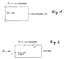
- a capacitor arrangement C via a resistor R here the internal resistance of the Accumulator
- time constant ⁇ R • C.
- a nickel-cadmium storage battery (rated at 1.2 V) is connected to a power source having an absolute voltage of at least 42 V and an absolute current of at least 1.5 times the short circuit current I to give K is capable.
- experiments have shown that the effect of the invention the reduction is established in the internal resistance of the battery cell at about 60 volts DC and about 225 A direct current, when this energy (13.5 kW) for about 2 msec to the nickel
- 300 V DC of approximately 10 kA DC is applied to the nickel-cadmium cell for 2 msec.
- Fig. 2 shows a possible circuit arrangement for implementation the method according to the invention.
- the shown capacitor assembly has a capacity of about 80 ⁇ Farad to about 250 m Farad (preferably about 7 m Farad) a dielectric strength of about 500 V.
- the nickel-cadmium accumulator connecting with the capacitor arrangement C.
- Switch S can be used as a manually operable circuit breaker or as an electronically controllable power semiconductor switch be designed.
- the charging of the capacitor arrangement C takes place (in a manner not further illustrated) from the Electricity supply via a rectifier.
- a nickel-cadmium storage battery which is charged according to the invention for about 0.2 to 5 msec at 300 V DC with about 10 kA DC, has in later operation at a discharge current of 20 A an increased output voltage by 20 mV (per single cell). This corresponds to a reduced by 1 m ⁇ internal resistance R i .
Landscapes
- Engineering & Computer Science (AREA)
- Manufacturing & Machinery (AREA)
- Chemical & Material Sciences (AREA)
- Chemical Kinetics & Catalysis (AREA)
- Electrochemistry (AREA)
- General Chemical & Material Sciences (AREA)
- Power Engineering (AREA)
- Secondary Cells (AREA)
- Battery Electrode And Active Subsutance (AREA)
Abstract
Claims (14)
- Procédé pour réduire la résistance interne (Ri) d'accumulateurs rechargeables sortant de l'usine, notamment des accumulateurs au nickel et au cadmium, selon lequel on raccorde aux pôles (+/-) de l'accumulateur une source d'énergie électrique, qui est conçue pour délivrer une énergie électrique égale au moins à 40 fois le produit du courant de court-circuit en valeur absolue (IK) par la tension nominale en valeur absolue d'un accumulateur non traité, et selon lequel on charge l'accumulateur avec l'énergie pendant un intervalle de temps prédéterminé.
- Procédé selon la revendication 1, selon lequel la source d'énergie est une source de tension continue, dont la borne positive (+) est reliée à l'anode de l'accumulateur et dont la borne négative (-) est reliée à la cathode de l'accumulateur.
- Procédé selon la revendication 1, selon lequel la source d'énergie est une source de tension continue, dont la borne positive est reliée à la cathode de l'accumulateur et dont la borne négative est reliée à l'anode de l'accumulateur.
- Procédé selon la revendication 1, selon lequel la source d'énergie est une source de tension alternative comportant deux bornes de sortie, dont l'une est reliée à l'anode et l'autre à la cathode de l'accumulateur.
- Procédé selon l'une des revendications 1 à 4, selon lequel la source d'énergie est reliée pendant au moins une microseconde (1 µs) à l'accumulateur, pour charger ce dernier avec l'énergie électrique.
- Procédé selon la revendication 5, selon lequel la source d'énergie est branchée et débranchée alternativement de façon répétée.
- Procédé selon l'une des revendications 1 à 4, caractérisé en ce que la source d'énergie est conçue pour délivrer au moins 1,5 fois le courant de court-circuit (IK) et entre 40 et 30 fois la tension nominale de l'accumulateur.
- Procédé selon la revendication 7, selon lequel la source d'énergie est conçu pour délivrer au moins 1,5 fois le courant de court-circuit (IK) et 40 fois la tension nominale de l'accumulateur.
- Procédé selon la revendication 8, selon lequel la source d'énergie est conçue pour délivrer 60 fois le courant de court-circuit et 300 fois la tension nominale de l'accumulateur.
- Procédé selon l'une des revendications 7 à 9, selon lequel la source d'énergie est reliée pendant au moins 1 µs à l'accumulateur pour charger ce dernier avec l'énergie électrique.
- Procédé selon la revendication 10, caractérisé en ce que la source d'énergie est branchée et débranchée alternativement de façon répétée.
- Procédé selon l'une des revendications 1 à 11, selon lequel on traite individuellement chaque cellule d'un accumulateur possédant plusieurs cellules est traitée.
- Procédé selon l'une des revendications 1 à 12, selon lequel on traite plusieurs cellules en parallèle, le courant étant accru conformément au nombre des cellules.
- Procédé selon l'une des revendications 1 à 12, selon lequel on traite plusieurs cellules branchées en série, la tension étant accrue conformément au nombre des cellules.
Applications Claiming Priority (1)
| Application Number | Priority Date | Filing Date | Title |
|---|---|---|---|
| PCT/EP1996/001710 WO1997040544A1 (fr) | 1996-04-24 | 1996-04-24 | Procede pour reduire la resistance interne d'accumulateurs rechargeables |
Publications (2)
| Publication Number | Publication Date |
|---|---|
| EP0835532A1 EP0835532A1 (fr) | 1998-04-15 |
| EP0835532B1 true EP0835532B1 (fr) | 2005-12-28 |
Family
ID=8166209
Family Applications (1)
| Application Number | Title | Priority Date | Filing Date |
|---|---|---|---|
| EP96914982A Expired - Lifetime EP0835532B1 (fr) | 1996-04-24 | 1996-04-24 | Procede pour reduire la resistance interne d'accumulateurs rechargeables |
Country Status (7)
| Country | Link |
|---|---|
| US (1) | US5905363A (fr) |
| EP (1) | EP0835532B1 (fr) |
| JP (1) | JP3561524B2 (fr) |
| KR (1) | KR100397481B1 (fr) |
| AU (1) | AU5692296A (fr) |
| DE (2) | DE59611318D1 (fr) |
| WO (1) | WO1997040544A1 (fr) |
Families Citing this family (10)
| Publication number | Priority date | Publication date | Assignee | Title |
|---|---|---|---|---|
| JP3547927B2 (ja) * | 1996-07-10 | 2004-07-28 | 三洋電機株式会社 | アルカリ蓄電池およびその製造方法 |
| US6118251A (en) * | 1999-01-27 | 2000-09-12 | The United States Of America As Represented By The Secretary Of The Army | Battery depassivation and conditioning method and apparatus |
| JP4039792B2 (ja) | 1999-08-27 | 2008-01-30 | 三洋電機株式会社 | 蓄電池およびその製造方法 |
| US6172486B1 (en) * | 1999-09-24 | 2001-01-09 | The United States Of America As Represented By The Secretary Of The Army | Battery life extender with engine heat |
| US6566844B1 (en) | 1999-10-06 | 2003-05-20 | Battery Performance Technologies, Inc. | Method and apparatus for extending the functionality of a battery |
| WO2002035679A1 (fr) * | 2000-10-26 | 2002-05-02 | Curtis Henry Dobbie | Système et procédé de chargement de batteries rechargeables |
| US6469473B1 (en) | 2001-03-16 | 2002-10-22 | Battery Performance Technologies, Inc. | Method and apparatus for using pulse current to extend the functionality of a battery |
| US8623301B1 (en) | 2008-04-09 | 2014-01-07 | C3 International, Llc | Solid oxide fuel cells, electrolyzers, and sensors, and methods of making and using the same |
| WO2011100361A2 (fr) | 2010-02-10 | 2011-08-18 | C3 International. Llc | Électrolytes fonctionnant à basse température pour piles à oxyde solide présentant une conductivité ionique élevée |
| EP3022792B1 (fr) | 2013-07-15 | 2024-09-11 | Fcet, Inc. | Piles à oxyde solide à basse température |
Family Cites Families (8)
| Publication number | Priority date | Publication date | Assignee | Title |
|---|---|---|---|---|
| GB8319187D0 (en) * | 1983-07-15 | 1983-08-17 | Morris N | Dry cell battery re-activator |
| US4829225A (en) * | 1985-10-23 | 1989-05-09 | Electronic Power Devices, Corp. | Rapid battery charger, discharger and conditioner |
| CH677560A5 (en) * | 1989-07-17 | 1991-05-31 | Siemens Ag Albis | Avoidance of short circuits in rechargeable battery cells - having current pulses applied to break down macroscopic metal bridging |
| JP2616077B2 (ja) * | 1989-12-27 | 1997-06-04 | 三菱電機株式会社 | 電池の活性化方法及びその装置 |
| USRE35643E (en) * | 1990-10-16 | 1997-10-28 | Motor Products International, Inc. | Lead acid battery rejuvenator and charger |
| US5063341A (en) * | 1990-10-16 | 1991-11-05 | Gali Carl E | Lead acid battery rejuvenator and charger |
| JPH0670478A (ja) * | 1992-08-20 | 1994-03-11 | Ebatoron:Kk | スパイク波による蓄電池の充電方法およびその装置 |
| DE4308538A1 (de) * | 1993-03-17 | 1994-09-22 | Rotermund Ulli | Verfahren und Vorrichtung zum Regenerieren von Spannungsquellen in Form galvanischer Elemente, insbesondere von Primärelementen |
-
1996
- 1996-04-24 EP EP96914982A patent/EP0835532B1/fr not_active Expired - Lifetime
- 1996-04-24 US US08/973,841 patent/US5905363A/en not_active Expired - Lifetime
- 1996-04-24 KR KR1019970709609A patent/KR100397481B1/ko not_active Expired - Lifetime
- 1996-04-24 AU AU56922/96A patent/AU5692296A/en not_active Abandoned
- 1996-04-24 JP JP53763397A patent/JP3561524B2/ja not_active Expired - Lifetime
- 1996-04-24 DE DE59611318T patent/DE59611318D1/de not_active Expired - Lifetime
- 1996-04-24 DE DE19681411T patent/DE19681411D2/de not_active Expired - Fee Related
- 1996-04-24 WO PCT/EP1996/001710 patent/WO1997040544A1/fr not_active Ceased
Also Published As
| Publication number | Publication date |
|---|---|
| KR100397481B1 (ko) | 2003-11-19 |
| AU5692296A (en) | 1997-11-12 |
| KR19990028295A (ko) | 1999-04-15 |
| JP3561524B2 (ja) | 2004-09-02 |
| US5905363A (en) | 1999-05-18 |
| EP0835532A1 (fr) | 1998-04-15 |
| DE19681411D2 (de) | 1998-08-20 |
| JPH11514135A (ja) | 1999-11-30 |
| WO1997040544A1 (fr) | 1997-10-30 |
| DE59611318D1 (de) | 2006-02-02 |
Similar Documents
| Publication | Publication Date | Title |
|---|---|---|
| EP3593435B1 (fr) | Procédé de fonctionnement d'un système d'accumulateur modulaire et système d'accumulateur modulaire | |
| EP0835532B1 (fr) | Procede pour reduire la resistance interne d'accumulateurs rechargeables | |
| EP2786467A2 (fr) | Procédé et dispositif de charge d'éléments de batteries rechargeables | |
| WO2008155209A1 (fr) | Bloc de batteries avec commutation pour fonctionnement par courant de haute intensité | |
| DE112012003131T5 (de) | Ladesteuerungsvorrichtung und Ladesteuerungsverfahren für eine Sekundärbatterie | |
| DE102015002072A1 (de) | Einstellen von Ladungszuständen von Batteriezellen | |
| WO2009146952A1 (fr) | Accumulateur d'énergie électrique | |
| EP3676933A1 (fr) | Dispositif d'électropolissage d'un accumulateur d'énergie présentant au moins un élément au lithium-ion, appareil de charge et procédé de fonctionnement de l'appareil de charge | |
| EP0114871B1 (fr) | Procede et dispositif pour le controle de la capacite a chaque fois chargee d'accumulateurs | |
| EP2862255A2 (fr) | Dispositif de commutation pour une batterie et procédé de commutation correspondant | |
| EP0616410A2 (fr) | Procédé et dispositif de régénération de sources de tension sous la forme d'éléments primaires | |
| WO2010060400A2 (fr) | Procédé et dispositif pour charger des accumulateurs | |
| DE102019212000A1 (de) | Batterieschaltung zum Einstellen von Ladungszuständen von Batterieelementen sowie Verfahren zum Betreiben einer Batterieschaltung | |
| DE2928503A1 (de) | Verfahren und vorrichtung zur vollund/oder ausgleichsladung von mehrzelligen akkumulaturenbatterien bei bregenzter gesamtspannung | |
| WO2020109532A1 (fr) | Cellule de batterie, procédé de chauffage d'une cellule de batterie et module de batterie | |
| DE102016224005A1 (de) | Elektrische Energiespeichereinrichtung | |
| DE2521785C3 (de) | Verfahren zur Herstellung eines tagerfähigen Bleiakkumulators | |
| DE385923C (de) | Elektrolytischer Spannungsteiler zum Betriebe von Schwachstromeinrichtungen aus Starkstromnetzen | |
| CH636483A5 (en) | Substance which is suitable as the active substance for positive electrodes of accumulators | |
| DE102018207373A1 (de) | Umrichtervorrichtung für einen Elektromotor | |
| DE102004018310A1 (de) | Vorrichtung zum Laden/Entladen einer Fahrzeug-Batterie | |
| DE1922385C3 (de) | Verfahren und Schaltungsanordnung zum Schnelladen einer elektrischen Batterie | |
| EP4513698A1 (fr) | Formation de cellules de batterie rechargeables au moyen d'une source d'énergie | |
| DE4338463A1 (de) | Elektrisch betriebenes Fahrzeugsystem | |
| EP1587202B1 (fr) | Méthode et appareil pour charger une batterie |
Legal Events
| Date | Code | Title | Description |
|---|---|---|---|
| PUAI | Public reference made under article 153(3) epc to a published international application that has entered the european phase |
Free format text: ORIGINAL CODE: 0009012 |
|
| AK | Designated contracting states |
Kind code of ref document: A1 Designated state(s): DE FR GB |
|
| 17P | Request for examination filed |
Effective date: 19991029 |
|
| 17Q | First examination report despatched |
Effective date: 20020214 |
|
| GRAP | Despatch of communication of intention to grant a patent |
Free format text: ORIGINAL CODE: EPIDOSNIGR1 |
|
| GRAS | Grant fee paid |
Free format text: ORIGINAL CODE: EPIDOSNIGR3 |
|
| RAP1 | Party data changed (applicant data changed or rights of an application transferred) |
Owner name: SANYO ELECTRIC CO., LTD. |
|
| GRAA | (expected) grant |
Free format text: ORIGINAL CODE: 0009210 |
|
| AK | Designated contracting states |
Kind code of ref document: B1 Designated state(s): DE FR GB |
|
| REG | Reference to a national code |
Ref country code: GB Ref legal event code: FG4D Free format text: NOT ENGLISH |
|
| REF | Corresponds to: |
Ref document number: 59611318 Country of ref document: DE Date of ref document: 20060202 Kind code of ref document: P |
|
| GBT | Gb: translation of ep patent filed (gb section 77(6)(a)/1977) |
Effective date: 20060322 |
|
| ET | Fr: translation filed | ||
| PLBE | No opposition filed within time limit |
Free format text: ORIGINAL CODE: 0009261 |
|
| STAA | Information on the status of an ep patent application or granted ep patent |
Free format text: STATUS: NO OPPOSITION FILED WITHIN TIME LIMIT |
|
| 26N | No opposition filed |
Effective date: 20060929 |
|
| REG | Reference to a national code |
Ref country code: FR Ref legal event code: PLFP Year of fee payment: 20 |
|
| PGFP | Annual fee paid to national office [announced via postgrant information from national office to epo] |
Ref country code: DE Payment date: 20150422 Year of fee payment: 20 Ref country code: GB Payment date: 20150422 Year of fee payment: 20 |
|
| PGFP | Annual fee paid to national office [announced via postgrant information from national office to epo] |
Ref country code: FR Payment date: 20150408 Year of fee payment: 20 |
|
| REG | Reference to a national code |
Ref country code: DE Ref legal event code: R071 Ref document number: 59611318 Country of ref document: DE |
|
| REG | Reference to a national code |
Ref country code: GB Ref legal event code: PE20 Expiry date: 20160423 |
|
| PG25 | Lapsed in a contracting state [announced via postgrant information from national office to epo] |
Ref country code: GB Free format text: LAPSE BECAUSE OF EXPIRATION OF PROTECTION Effective date: 20160423 |