EP0835722B1 - Verfahren und Vorrichtung zum Herstellen einer Kunststofflinse - Google Patents
Verfahren und Vorrichtung zum Herstellen einer Kunststofflinse Download PDFInfo
- Publication number
- EP0835722B1 EP0835722B1 EP97117491A EP97117491A EP0835722B1 EP 0835722 B1 EP0835722 B1 EP 0835722B1 EP 97117491 A EP97117491 A EP 97117491A EP 97117491 A EP97117491 A EP 97117491A EP 0835722 B1 EP0835722 B1 EP 0835722B1
- Authority
- EP
- European Patent Office
- Prior art keywords
- block material
- tool
- processing
- grinding
- smoothing
- Prior art date
- Legal status (The legal status is an assumption and is not a legal conclusion. Google has not performed a legal analysis and makes no representation as to the accuracy of the status listed.)
- Expired - Lifetime
Links
- 229920003023 plastic Polymers 0.000 title claims description 39
- 239000004033 plastic Substances 0.000 title claims description 39
- 238000004519 manufacturing process Methods 0.000 title claims description 21
- 239000000463 material Substances 0.000 claims description 88
- 238000000227 grinding Methods 0.000 claims description 41
- 238000009499 grossing Methods 0.000 claims description 37
- 238000005498 polishing Methods 0.000 claims description 36
- 238000000034 method Methods 0.000 claims description 30
- -1 polyethylene Polymers 0.000 claims description 23
- 229920005989 resin Polymers 0.000 claims description 19
- 239000011347 resin Substances 0.000 claims description 19
- IISBACLAFKSPIT-UHFFFAOYSA-N bisphenol A Chemical class C=1C=C(O)C=CC=1C(C)(C)C1=CC=C(O)C=C1 IISBACLAFKSPIT-UHFFFAOYSA-N 0.000 claims description 18
- 239000000758 substrate Substances 0.000 claims description 15
- 229920001187 thermosetting polymer Polymers 0.000 claims description 13
- 239000004677 Nylon Substances 0.000 claims description 12
- 229920001577 copolymer Polymers 0.000 claims description 12
- MTHSVFCYNBDYFN-UHFFFAOYSA-N diethylene glycol Chemical compound OCCOCCO MTHSVFCYNBDYFN-UHFFFAOYSA-N 0.000 claims description 12
- 229920001778 nylon Polymers 0.000 claims description 12
- 230000000694 effects Effects 0.000 claims description 10
- 230000000750 progressive effect Effects 0.000 claims description 10
- 238000003860 storage Methods 0.000 claims description 10
- NIXOWILDQLNWCW-UHFFFAOYSA-M Acrylate Chemical compound [O-]C(=O)C=C NIXOWILDQLNWCW-UHFFFAOYSA-M 0.000 claims description 8
- 239000004642 Polyimide Substances 0.000 claims description 8
- 229920000728 polyester Polymers 0.000 claims description 8
- 229920001721 polyimide Polymers 0.000 claims description 8
- 229920005992 thermoplastic resin Polymers 0.000 claims description 8
- 229920000642 polymer Polymers 0.000 claims description 5
- MHHJQVRGRPHIMR-UHFFFAOYSA-N 1-phenylprop-2-en-1-ol Chemical compound C=CC(O)C1=CC=CC=C1 MHHJQVRGRPHIMR-UHFFFAOYSA-N 0.000 claims description 4
- 239000004953 Aliphatic polyamide Substances 0.000 claims description 4
- 229920002160 Celluloid Polymers 0.000 claims description 4
- DQEFEBPAPFSJLV-UHFFFAOYSA-N Cellulose propionate Chemical compound CCC(=O)OCC1OC(OC(=O)CC)C(OC(=O)CC)C(OC(=O)CC)C1OC1C(OC(=O)CC)C(OC(=O)CC)C(OC(=O)CC)C(COC(=O)CC)O1 DQEFEBPAPFSJLV-UHFFFAOYSA-N 0.000 claims description 4
- 229920000106 Liquid crystal polymer Polymers 0.000 claims description 4
- 239000004977 Liquid-crystal polymers (LCPs) Substances 0.000 claims description 4
- 239000004696 Poly ether ether ketone Substances 0.000 claims description 4
- 229930182556 Polyacetal Natural products 0.000 claims description 4
- 239000004695 Polyether sulfone Substances 0.000 claims description 4
- 239000004697 Polyetherimide Substances 0.000 claims description 4
- 239000004698 Polyethylene Substances 0.000 claims description 4
- 239000004721 Polyphenylene oxide Substances 0.000 claims description 4
- 239000004743 Polypropylene Substances 0.000 claims description 4
- 239000004793 Polystyrene Substances 0.000 claims description 4
- 239000004372 Polyvinyl alcohol Substances 0.000 claims description 4
- 229920001328 Polyvinylidene chloride Polymers 0.000 claims description 4
- UCKMPCXJQFINFW-UHFFFAOYSA-N Sulphide Chemical compound [S-2] UCKMPCXJQFINFW-UHFFFAOYSA-N 0.000 claims description 4
- 239000004433 Thermoplastic polyurethane Substances 0.000 claims description 4
- 229920000122 acrylonitrile butadiene styrene Polymers 0.000 claims description 4
- 229920003231 aliphatic polyamide Polymers 0.000 claims description 4
- 239000004760 aramid Substances 0.000 claims description 4
- 229920003235 aromatic polyamide Polymers 0.000 claims description 4
- 125000003118 aryl group Chemical group 0.000 claims description 4
- 229920002301 cellulose acetate Polymers 0.000 claims description 4
- 229920001727 cellulose butyrate Polymers 0.000 claims description 4
- 229920006218 cellulose propionate Polymers 0.000 claims description 4
- 239000012461 cellulose resin Substances 0.000 claims description 4
- 239000003822 epoxy resin Substances 0.000 claims description 4
- 239000005038 ethylene vinyl acetate Substances 0.000 claims description 4
- 229920002313 fluoropolymer Polymers 0.000 claims description 4
- 239000004811 fluoropolymer Substances 0.000 claims description 4
- 229920000554 ionomer Polymers 0.000 claims description 4
- 229920001643 poly(ether ketone) Polymers 0.000 claims description 4
- 229920001200 poly(ethylene-vinyl acetate) Polymers 0.000 claims description 4
- 229920002492 poly(sulfone) Polymers 0.000 claims description 4
- 229920006122 polyamide resin Polymers 0.000 claims description 4
- 229920001230 polyarylate Polymers 0.000 claims description 4
- 229920001707 polybutylene terephthalate Polymers 0.000 claims description 4
- 229920000515 polycarbonate Polymers 0.000 claims description 4
- 239000004417 polycarbonate Substances 0.000 claims description 4
- 229920000647 polyepoxide Polymers 0.000 claims description 4
- 229920006393 polyether sulfone Polymers 0.000 claims description 4
- 229920002530 polyetherether ketone Polymers 0.000 claims description 4
- 229920001601 polyetherimide Polymers 0.000 claims description 4
- 229920000573 polyethylene Polymers 0.000 claims description 4
- 229920000139 polyethylene terephthalate Polymers 0.000 claims description 4
- 229920000306 polymethylpentene Polymers 0.000 claims description 4
- 239000011116 polymethylpentene Substances 0.000 claims description 4
- 229920000098 polyolefin Polymers 0.000 claims description 4
- 229920006324 polyoxymethylene Polymers 0.000 claims description 4
- 229920006389 polyphenyl polymer Polymers 0.000 claims description 4
- 229920006380 polyphenylene oxide Polymers 0.000 claims description 4
- 229920001155 polypropylene Polymers 0.000 claims description 4
- 229920002223 polystyrene Polymers 0.000 claims description 4
- 229920002635 polyurethane Polymers 0.000 claims description 4
- 239000004814 polyurethane Substances 0.000 claims description 4
- 229920002451 polyvinyl alcohol Polymers 0.000 claims description 4
- 239000004800 polyvinyl chloride Substances 0.000 claims description 4
- 229920000915 polyvinyl chloride Polymers 0.000 claims description 4
- 239000005033 polyvinylidene chloride Substances 0.000 claims description 4
- 229920006395 saturated elastomer Polymers 0.000 claims description 4
- 229920002803 thermoplastic polyurethane Polymers 0.000 claims description 4
- 229920006305 unsaturated polyester Polymers 0.000 claims description 4
- 125000000391 vinyl group Chemical group [H]C([*])=C([H])[H] 0.000 claims description 4
- 229920002554 vinyl polymer Polymers 0.000 claims description 4
- 239000005020 polyethylene terephthalate Substances 0.000 claims description 3
- 239000002826 coolant Substances 0.000 description 7
- 238000009472 formulation Methods 0.000 description 7
- 239000000203 mixture Substances 0.000 description 7
- 238000006073 displacement reaction Methods 0.000 description 5
- 239000011521 glass Substances 0.000 description 5
- 239000007788 liquid Substances 0.000 description 5
- 229910052782 aluminium Inorganic materials 0.000 description 4
- XAGFODPZIPBFFR-UHFFFAOYSA-N aluminium Chemical compound [Al] XAGFODPZIPBFFR-UHFFFAOYSA-N 0.000 description 4
- 229910003460 diamond Inorganic materials 0.000 description 4
- 239000010432 diamond Substances 0.000 description 4
- 239000000470 constituent Substances 0.000 description 2
- 230000001419 dependent effect Effects 0.000 description 2
- 238000007688 edging Methods 0.000 description 2
- 238000002360 preparation method Methods 0.000 description 2
- 230000003746 surface roughness Effects 0.000 description 2
- 230000001360 synchronised effect Effects 0.000 description 2
- XLYOFNOQVPJJNP-UHFFFAOYSA-N water Substances O XLYOFNOQVPJJNP-UHFFFAOYSA-N 0.000 description 2
- NIXOWILDQLNWCW-UHFFFAOYSA-N acrylic acid group Chemical group C(C=C)(=O)O NIXOWILDQLNWCW-UHFFFAOYSA-N 0.000 description 1
- 230000002411 adverse Effects 0.000 description 1
- 239000002518 antifoaming agent Substances 0.000 description 1
- 239000007864 aqueous solution Substances 0.000 description 1
- 238000007796 conventional method Methods 0.000 description 1
- 230000007423 decrease Effects 0.000 description 1
- 125000004386 diacrylate group Chemical group 0.000 description 1
- 230000003292 diminished effect Effects 0.000 description 1
- 235000019589 hardness Nutrition 0.000 description 1
- JEIPFZHSYJVQDO-UHFFFAOYSA-N iron(III) oxide Inorganic materials O=[Fe]O[Fe]=O JEIPFZHSYJVQDO-UHFFFAOYSA-N 0.000 description 1
- 238000002844 melting Methods 0.000 description 1
- 230000008018 melting Effects 0.000 description 1
- 229910001092 metal group alloy Inorganic materials 0.000 description 1
- 230000003287 optical effect Effects 0.000 description 1
- 239000002245 particle Substances 0.000 description 1
- 229920000058 polyacrylate Polymers 0.000 description 1
- 230000003449 preventive effect Effects 0.000 description 1
- 229920002379 silicone rubber Polymers 0.000 description 1
- 239000004945 silicone rubber Substances 0.000 description 1
Images
Classifications
-
- B—PERFORMING OPERATIONS; TRANSPORTING
- B23—MACHINE TOOLS; METAL-WORKING NOT OTHERWISE PROVIDED FOR
- B23Q—DETAILS, COMPONENTS, OR ACCESSORIES FOR MACHINE TOOLS, e.g. ARRANGEMENTS FOR COPYING OR CONTROLLING; MACHINE TOOLS IN GENERAL CHARACTERISED BY THE CONSTRUCTION OF PARTICULAR DETAILS OR COMPONENTS; COMBINATIONS OR ASSOCIATIONS OF METAL-WORKING MACHINES, NOT DIRECTED TO A PARTICULAR RESULT
- B23Q3/00—Devices holding, supporting, or positioning work or tools, of a kind normally removable from the machine
- B23Q3/155—Arrangements for automatic insertion or removal of tools, e.g. combined with manual handling
- B23Q3/157—Arrangements for automatic insertion or removal of tools, e.g. combined with manual handling of rotary tools
-
- B—PERFORMING OPERATIONS; TRANSPORTING
- B24—GRINDING; POLISHING
- B24B—MACHINES, DEVICES, OR PROCESSES FOR GRINDING OR POLISHING; DRESSING OR CONDITIONING OF ABRADING SURFACES; FEEDING OF GRINDING, POLISHING, OR LAPPING AGENTS
- B24B13/00—Machines or devices designed for grinding or polishing optical surfaces on lenses or surfaces of similar shape on other work; Accessories therefor
- B24B13/0031—Machines having several working posts; Feeding and manipulating devices
- B24B13/0037—Machines having several working posts; Feeding and manipulating devices the lenses being worked by different tools, e.g. for rough-grinding, fine-grinding, polishing
-
- B—PERFORMING OPERATIONS; TRANSPORTING
- B24—GRINDING; POLISHING
- B24B—MACHINES, DEVICES, OR PROCESSES FOR GRINDING OR POLISHING; DRESSING OR CONDITIONING OF ABRADING SURFACES; FEEDING OF GRINDING, POLISHING, OR LAPPING AGENTS
- B24B45/00—Means for securing grinding wheels on rotary arbors
- B24B45/003—Accessories therefor
-
- B—PERFORMING OPERATIONS; TRANSPORTING
- B29—WORKING OF PLASTICS; WORKING OF SUBSTANCES IN A PLASTIC STATE IN GENERAL
- B29D—PRODUCING PARTICULAR ARTICLES FROM PLASTICS OR FROM SUBSTANCES IN A PLASTIC STATE
- B29D11/00—Producing optical elements, e.g. lenses or prisms
- B29D11/00932—Combined cutting and grinding thereof
- B29D11/00942—Combined cutting and grinding thereof where the lens material is mounted in a support for mounting onto a cutting device, e.g. a lathe, and where the support is of machinable material, e.g. plastics
Definitions
- This invention relates to an apparatus for and a method of the production of plastic lens substrate, as per the preamble of claims 1 and 11.
- An example of such an apparatus and method is disclosed in EP 453 627 A.
- a plastic block material suited as a plastic lens substrate for use in eyeglasses has been produced from processing of one of its two surfaces by means of three processing steps, i.e., grinding, smoothing and polishing.
- the plastic block material (referred to hereinafter as the block material) denotes a thick-walled lens having already been processed on a convex side but being still required to be processed so as to gain a lens thickness and a concave side as desired.
- the block material is a so-called semi-finished lens. Details as regards each of the process steps stated above will be described below.
- the grinding step is intended to cut one selected surface of the block material (hereunder called a lens forming surface) in such a manner that a desired radius is attained on the lens forming surface.
- a diamond wheel is employed which is known as a cup-shaped tool having diamond particles electro-deposited on its grinding face.
- the diamond wheel is caused to axially rotate and then brought into movable contact on the particulate diamond-deposited face with the lens forming surface of the block material, while a coolant is being applied to the lens forming surface.
- the coolant is usually water or an aqueous solution in which a rust preventive, an antifoaming agent and the like are contained.
- the smoothing step follows upon completion of the grinding step.
- the smoothing step is intended to render fine or smooth the lens forming surface of the block material, which lens forming surface has been cut to a predetermined radius but with some surface roughness through the grinding step.
- the smoothing step is effected by use of an aluminum tray provided with a face having a radius to correspond to that defined on the lens forming surface of the block material. Disposed adhesively over that tray face is a sheet-like polishing medium commonly called a smoothing pad for exclusive use in such a step of smoothing.
- the aluminum tray mentioned here is known as a processing tray.
- the processing tray is manipulated to rotate such that during application of a coolant, the polishing medium is allowed to slidably contact with the lens forming surface of the block material.
- the block material processed to have reduced surface roughness on the lens forming surface through the smoothing step is thereafter subjected to the polishing step as a finishing operation.
- the polishing step contemplates imparting greater fineness or smoothness to the lens forming surface having undergone processing via the smoothing step. Also in the polishing step, use is made of an aluminum tray of the type stated previously in connection with the smoothing step having a face radially shaped to fit the lens forming surface of the block material.
- a polishing medium (a polishing pad, for example) to be adhesively mounted on the aluminum tray is softer in nature and smaller in mesh than that employed in the smoothing step.
- the polishing step is achieved by bringing the resulting processing tray into slidable contact with the lens forming surface, while a polishing liquid is being applied to the latter.
- the block material has been processed on its lens forming surface by means of the three process steps as discussed above. In each such step, each individual exclusive processing apparatus is employed.
- the conventional production method needs a separate processing apparatus so as to carry out each process step of grinding, smoothing and polishing of a plastic block material. Such method, therefore, leads to an increase in equipment cost and in floor space. Additionally, many different processing trays are needed to cope with varying radii desired to be processed in both of the smoothing and polishing steps. Those processing trays cause burdens of time and cost for their preparation. Furthermore, the radii to be processed are dependent upon the formulations of lenses that are variable with the requests to be made by individual users. A large number of radii are required to be satisfied in order to tailor users' needs. However, because of a great expenditure of time and effort to prepare processing trays, inventories are necessary for those trays of a wide variety of kinds. This literally results in added storage space and increased cost investment in advance. The foregoing problems create an obstacle to improved lens productivity and to saved production cost.
- the conventional production method using processing trays requires that the trays be brought into slidable contact with a lens forming surface of a plastic block material with the result that possible processing is limited to a spherical lens and a toric lens.
- the plastic lens generator comprises a rotatable chuck for rotating an optical lens blank, two drive systems and a cutter.
- a computer control is operably associated with the drive systems for coordinating displacement of the associated chuck and cutter for causing a selected curvature to be generated on the blank.
- the present invention has been made to solve or eliminate the aforementioned problems experienced in the production method of the prior art.
- a pad adhesively attached to the processing tray for use in each of the smoothing and polishing steps must be replaced with a new one every time one block material is completely processed. Releasing of a spent pad and attachment of a fresh pad have been found to be tedious with a lot of effort and manpower.
- Still another finding is that it is inconvenient to find a processing tray of a desirable radius out of a wide variety of inventories.
- the desired processing tray would sometimes be tried in vain to find when the same is being used in another step. In such instance, some waiting time would be spent until the processing tray is made available. This is responsible for a decline in production efficiency.
- the plastic block material may preferably be chosen from one of thermoplastic resins and thermosetting resins.
- the thermoplastic resins may be cellulose resins (such as celluloid, cellulose acetate, cellulose propionate, and cellulose butyrate), polyamide resins including aliphatic polyamide (such as 6-nylon, 6,6-nylon, and 12-nylon) and aromatic polyamide, polyolefins (such as ABS resin, AS resin, polystyrene, polyethylene and polypropylene), vinyl resins (such as polyvinyl chloride, polyvinylidene chloride, ethylene-vinyl acetate copolymer, and polyvinyl alcohol), saturated polyesters (such as polyacetal, polycarbonate, polyethylene terephthalate, and polybutylene terephthalate), aromatic polyesters, polyether ketone, polyether ether ketone, polysulfone, polyether sulfone, polyether imide, polyarylate, polymethyl pentene,
- thermosetting resins may be epoxy resin, unsaturated polyester, thermosetting polyurethane, polyimide, polymer of diethylene glycol bis-allycarbonate (CR-39), copolymer of bisphenol A or halogenated bisphenol A and diacrylate di(meth)acrylate, copolymer of bisphenol A or halogenated bisphenol A and urethane-modified di(meta)acrylate, or copolymer of a diacrylate compound or vinyl benzyl alcohol and an unsaturated thiol compound.
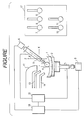
- the drawing is a schematic elevation illustrative of the apparatus of the invention.
- a plastic block material 1 is mounted in place on a retainer 2 located for retaining a processing material to be processed.
- the block material 1 is placed on its convex side to adhesively fit the retainer 2 with use of a metal alloy of a low melting point.
- One side of the retainer 2 is designed to retain the processing material or block material 1, and the other side is securely attached to an axis that is coupled with a manipulator 3.
- the manipulator 3 acts to permit rotation of the retainer 2, and to this end, a motor or the like can be used.
- the retainer 2 is movable in directions of X and/or Y and/or Z, and these movements are achievable by the action of an actuator 15. Though shown connected to the retainer 2 in the drawing, the actuator 15 may be united with the manipulator 3 in such a manner that the latter is allowed to move together with the manipulator 3.
- Each of the manipulator 3 and the actuator 15 communicates with a control unit 16.
- the control unit 16 controls the manipulator 3, thereby controlling the number of revolution and the speed of revolution in regard to the retainer 2 and also the on-off operation of the manipulator 3. Additionally, the control unit 16 controls the actuator 15, thereby controlling the X and/or Y and/or Z directions of movement, the distance of movement, the speed of movement and the on-off operation in regard to the retainer 2.
- a computer is preferably used as the control unit 16. While in arrangement illustrated in the drawing, both of the manipulator 3 and the actuator 15 are connected to the one single control unit 16, separate control units may be arranged with respect to the manipulator 3 and the actuator 15.
- a holder 5 disposed for holding a processing tool is positioned toward the side of the retainer 2 disposed for retaining the processing material or block material 1.
- the holder 5 is provided at one end thereof with a location for holding the processing tool and at the other opposite end with a manipulator 6.
- the manipulator 6 operates to enable axial rotation of the processing tool. For this operation, a motor, a high-frequency motor, an air spindle or the like can be put to use.
- the holder 5 is coupled with the actuator 15.
- the actuator 15 acts on the processing tool in respect of the X and/or Y and/or Z directions of movement, the distance of movement and the on-off operation as well as the inclination ( ⁇ ) of movement.
- the manipulator 6 is also coupled to the control unit 16.
- the control unit 16 acts to control the manipulator 6, thereby controlling the processing tool in respect of the X and/or Y and/or Z directions of movement, the distance of movement, the speed of movement and the on-off operation as well as the inclination ( ⁇ ) of movement and the on-off operation of inclination.
- a computer-aided unit can be used. If the axis of ⁇ is set at a degree of zero, then the processing tool actually works only at a region near to its top with consequential failure to attain a sufficient circumferential speed which could arise from rotation of the processing tool. Also adversely, such tool is liable to involve clogging or like inconvenience. For those reasons, the axis of ⁇ should be inclined in the practice of the present invention.
- those controls made via the manipulator 6 are performed by use of one control unit.
- individual control units may be arranged to effect the respective controls.
- the actuator 15 and the control unit 16 are arranged to actuate both of the retainer 2 and the holder 5 and to control the manipulators 3, 6 of these constituent parts.
- the actuator 15 and the control unit 16 may be held in separately operative relation to each other.
- an exhaust duct 12 Disposed upwardly laterally of the block material 1 are an exhaust duct 12, a coolant-supplying hose 13 and a polishing liquid-supplying hose 14.
- Duct exhaust, coolant supply and liquid supply are all effected by use of a computer-aided motor which is capable of making the on-off operations and of controlling the extents of exhaust and supply.
- a storage unit 17 for storing the processing tools is located adjacent to the tool holder 5.
- the storage unit 17 is constructed to accommodate a plurality of processing tools 7, 8, 9, 10, 11 of varying shapes, hardnesses and dimensions for adaptability to each of process steps of grinding, smoothing and polishing.
- the holder 5 moves to arrive at the storage unit 17, thus selecting any necessary tool for subsequent processing. The operator's discretion is used in that selection.
- Suitable processing tools for use in the grinding step include a ball end mill and an end mill, and eligible materials include diamond and an ultra-hard material.
- Suitable processing tools for use in the smoothing step are chosen from an electro-deposited whetstone and a resin-bonded whetstone.
- Suitable processing tools for use in the polishing step are chosen from a felt buff, a silicone rubber and a brush.
- the holder 5 and the retainer 2 may be allowed to move in the directions of X and/or Y and/or Z by movement of either one or both of the two constituent parts. Furthermore, the processing tool and the retainer 2 may be allowed to rotate by rotation of either one or both of the two parts.
- rotation of the block material and/or the processing tool movement of the block material and/or the processing tool, exchange of processing tools, local exhaust, and supply of the coolant and the polishing liquid are achieved by means of computer control.
- fixing and removal of the block material are required to be effected only once.
- Lens processing from grinding to polishing is automatically feasible with use of one set of production apparatus.
- rotation of the block material and/or the lens, rotation of the tool, and movement of the tool are conducted through numerical control aided by a computer so that lens surfaces such as an aspherical surface, a progressive surface, a combination of aspherical and toric surfaces and so on can be processed at will, which lens surfaces have been found unattainable by the method of the prior art.
- thermoplastic resins may be cellulose resins (such as celluloid, cellulose acetate, cellulose propionate, and cellulose butyrate), polyamide resins including aliphatic polyamide (such as 6-nylon, 6,6-nylon, and 12-nylon) and aromatic polyamide, polyolefins (such as ABS resin, AS resin, polystyrene, polyethylene and polypropylene), vinyl resins (such as polyvinyl chloride, polyvinylidene chloride, ethylene-vinyl acetate copolymer, and polyvinyl alcohol), saturated polyesters (such as polyacetal, polycarbonate, polyethylene terephthalate, and polybutylene terephthalate), aromatic polyesters, polyether ketone, polyether ether ketone, polysulfone, polyether sulfone, polyether
- thermosetting resins may be epoxy resin, unsaturated polyester, thermosetting polyurethane, polyimide, polymer of diethylene glycol bis-allycarbonate (CR-39), copolymer of bisphenol A or halogenated bisphenol A and di(meth)acrylate, copolymer of bisphenol A or halogenated bisphenol A and urethane-modified di(meth)acrylate, or copolymer of a diacrylate compound or vinyl benzyl alcohol and an unsaturated thiol compound.
- the thermosetting resins include, in addition to heat-curable resins, photo-curable resins such as of an acrylic class and the like.
- a plastic block material was processed to produce a plastic lens substrate.
- a plastics-made semi-finished lens (a polymer of CR-39) that had been processed to define a convex surface thereon was fixed on a processing material retainer with the convex side directed downwardly.
- the term semi-finished lens is meant a lens substrate prepared for processing a concave side thereon on a custom-made basis and according to a certain specific lens formulation.
- the semi-finished lens is provided with a convex surface previously processed.
- a concave surface was processed with a radius of 100 mm in consideration of the lens formulation and the convex shape of the semi-finished lens.
- the cutter-carrying holder was caused to move in Z and X directions and to locate peripherally of the block material.
- the lens was rotated at a speed of 4 rpm and the tool at 5,000 rpm.
- the block material was thereafter stock-removed with exhaust to a depth of about 3.0 mm in the Z direction, while the X axis was displaced at a speed of 2.80 mm/min from the periphery of the block material to the central direction. While in displacement of the Z axis, a concave surface of 100 mm in radius was processed.
- a diamond-electrodeposited whetstone No. 120 (Item No. A3608, spherical shape of 6.0 mm in radius) manufactured by MINITOR Co., Ltd. was selected and mounted on the tool holder.
- the whetstone-carrying holder was caused to move in the Z and X directions and to locate peripherally of the block material. With the ⁇ axis inclined at a degree of 30, the tool was rotated at a speed of 5,000 rpm.
- the block material was then stock-removed to a depth of 0.05 mm in the Z direction during supplying of water as a coolant, while the X axis was moved at a speed of 0.08 mm/min from the periphery of the block material to the central direction. While in displacement of the Z axis, a concave surface of 100 mm in radius was processed.
- a felt buff of a soft type (Item No. E5518, spherical shape of 10 mm in radius) manufactured by MINITOR Co., Ltd. was selected and mounted on the tool holder.
- the buff-carrying holder was caused to move in the Z and X directions and to locate peripherally of the block material. With the ⁇ axis inclined at a degree of 30, the block material was rotated at a speed of 4 rpm and the processing tool at 5,000 rpm.
- the block material was then stock-removed to a depth of 0.005 mm in the Z direction during supplying as a polishing liquid of Polipla 103A commercially obtained from Fujimi Incorporated, while the X axis was moved at a speed of 36 mm/min from the periphery of the block material to the central direction. While in displacement of the Z axis, a concave surface of 100 mm in radius was processed.
- a plastic lens substrate which was provided with a toric surface thereon was produced.
- a plastic block material use was made of a semi-finished lens formed of the same material as in that tested in Example 1 and processed to define a convex surface of a given curvature. This semi-finished lens was placed on a processing material retainer.
- the radii of a concave surface were set at 100 mm in a first axis and at 75 mm in a second axis orthogonal to the first axis with the shape of the semi-finished lens and the lens formulation taken in view.
- the same processing tool as used for grinding in Example 1 was chosen and mounted on a tool holder.
- the processing tool was displaced at Z and X axes and located peripherally of the block material.
- the tool holder was inclined at a degree of 30 with respect to the perpendicular line extending from a lens forming surface of the semi-finished lens and then caused to rotate with such conditions as of 4 rpm of the lens and 5,000 rpm of the tool.
- the axis of Z was controlled to displace through the movement synchronized with the angle of rotation of the semi-finished lens such that a toric surface was processed.
- this angle of rotation is meant the angle of the toric surface specified in accordance with the lens formulation.
- Example 1 As regards subsequent process steps of smoothing and polishing, the procedures of Example 1 were followed except that curvatures were set to meet with the above requirements of the toric surface.
- processing may be effected by controlling displacement of the Z axis through the movement synchronized with the angle of rotation of the semi-finished lens, thereby meeting with those free curvatures programmed by a computer or the like.
- a substrate to be subjected to grinding is a semi-finished lens which has not been adjusted in its diameter.
- the semi-finished lens can be processed on its edge face according to a certain piece of information that is made obtainable by counting a processable diameter of a lens substrate from the shape of a lens ready for attachment to glasses. This processing is commonly called chamfering.
- the chamfered lens is of a circular shape.
- edging can be conducted prior to grinding.
- Processing tools for use in chamfering and edging may be those used for grinding. More desirably, however, a cylindrical processing tool may be used which is shaped to be straight at a portion disposed for contact with the end face of the semi-finished lens.
- the polishing step alone can be effected with use of a separate apparatus.
- chamfering, grinding and smoothing are effected in one and the same apparatus and polishing alone in a second apparatus.
- the same set of processing tools is applicable to grinding, smoothing and chamfering.
- the production method can effect grinding, smoothing and polishing with only one cycle of fixing and removal of a processing material, eventually contributing to shortened processing.
- the method according to the invention causes such steps to be performed in one and the same apparatus and hence leads to saved equipment cost and reduced floor space. Further, saved storage space and saved preparation cost are attainable for processing trays since the latter are not necessary in the practice of the invention. This gives rise to reduced production cost of the processing material.
- lens surfaces such as an aspherical surface, a progressive surface and the like are processable when desired, which lens surfaces have been found unattainable by the method of the prior art.
- the prior art method using processing trays makes it markedly difficult to process, because of the need for a larger number of processing trays, special lens formulations of more or less 10 diopters on a spherical surface and of more or less than 4 diopters on a toric surface.
- the apparatus according to the invention has no need for such trays and has found satisfactorily applicable to specific lens formulations.
Landscapes
- Engineering & Computer Science (AREA)
- Mechanical Engineering (AREA)
- Health & Medical Sciences (AREA)
- Manufacturing & Machinery (AREA)
- Ophthalmology & Optometry (AREA)
- Grinding And Polishing Of Tertiary Curved Surfaces And Surfaces With Complex Shapes (AREA)
- Eyeglasses (AREA)
- Constituent Portions Of Griding Lathes, Driving, Sensing And Control (AREA)
- Moulds For Moulding Plastics Or The Like (AREA)
Claims (20)
- Eine Vorrichtung zur Herstellung eines Plastiklinsensubstrates durch Bearbeiten eines Plastikblockmaterials (1), die umfasst:dadurch gekennzeichnet, dasseinen Aufnehmer (2), zum Halten eines Plastikblockmaterials;eine Haltevorrichtung (5), zum Halten eines Bearbeitungswerkzeuges;einen Manipulator (3,6), zum Bewegen des Bearbeitungswerkzeuges und/oder des Blockmaterials beim Bearbeiten;einen Antrieb (15), der bewirkt die Werkzeughaltevorrichtung und/oder den Plastikblockaufnehmer so zu bewegen, dass das Bearbeitungswerkzeug und das Blockmaterial einer relativen Bewegung zueinander unterworfen werden;eine Steuerungseinheit (16), zum Steuern des Antriebs und/oder des Manipulators, so dass das Blockmaterial in eine gewünschte Form gebracht wird;
die Vorrichtung ferner umfasst:eine Speichereinheit (17), die Bearbeitungswerkzeuge (7-11) zur Verwendung in Schleif- und Glättbearbeitungsschritten speichert, wobei jedes der Bearbeitungswerkzeuge einen Bearbeitungswerkzeugendabschnitt hat, der so dimensioniert ist, dass er kleiner als die Abmessung des Blockmaterials (1) ist;die Steuerungseinheit (16) ist konfiguriert, um das Werkzeug zum Schleifen auszuwählen, um das Schleifen des Blockmaterials mit dem Schleifwerkzeug zu bewerkstelligen und um, nach Beendigung des Schleifens, das Schleifwerkzeug durch das Glättwerkzeug zu ersetzen, um mit dem Glättwerkzeug das Glätten des geschliffenen Blockmaterials zur bewerkstelligen. - Eine Vorrichtung nach Anspruch 1, wobei die Speichereinheit ferner ein Bearbeitungswerkzeug zur Verwendung in einem Polierschritt speichert, das einen Bearbeitungswerkzeugendabschnitt hat, der so dimensioniert ist, dass er kleiner als die Abmessung des Blockmaterials ist.
- Eine Vorrichtung nach Anspruch 1, wobei die Sehleifwerkzeuge zum Schleifen und zum Kantenbearbeiten verwendbar sind.
- Eine Vorrichtung nach Anspruch 1, wobei die Speichereinheit ferner ein Bearbeitungswerkzeug, zur Verwendung in einem Kantenbearbeitungsschritt, speichert, das einen Bearbeitungswerkzeugendabschnitt hat, der so dimensioniert ist, dass er kleiner als die Abmessung des Blockmaterials ist.
- Eine Vorrichtung nach Anspruch 2, wobei die Steuerungseinheit den Antrieb numerisch steuert, und dabei das Bearbeitungswerkzeug in Bezug zur X und/oder Y und/oder Z Richtung der relativen Bewegung bewegt, und
die Steuerungseinheit ferner konfiguriert ist, um, nach Beendigung des Glättens, das Glättwerkzeug durch das Polierwerkzeug zu ersetzen, um mit dem Polierwerkzeug das Polieren des geglätteten Blockmaterials zu bewerkstelligen. - Eine Vorrichtung nach Anspruch 2, wobei das Plastikblockmaterial aus thermoplastischen Harzen und duroplastischen Harzen ausgewählt ist.
- Eine Vorrichtung nach Anspruch 6, wobei die thermoplastischen Harze und die duroplastischen Harzen aus der Gruppe ausgewählt sind, die besteht aus:Zelluloseharze, wie Zelluloid, Zelluloseacetat, Zellulosepropinat und Zellulosebutyrat; Polyamidharze einschließlich aliphatische Polyamide, wie 6-Nylon, 6,6-Nylon und 12-Nylon und aromatische Polyamide; Polyolefine, wie ABS-Harz, AS-Harz, Polystyrol, Polyethylen und Polypropylen; Vinylharze, wie Polyvinylchlorid, Polyvinylidenchlorid, Ethylen-Vinyl-Acetat-Copolymer und Polyvinylalkohol; gesättigte Polyester, wie Polyacetalharz, Polycarbonat, Polyethylenterephtalat und Polybutylenterephtalat; aromatische Polyester; Polyetherketon; Polyetheretherketon; Polysulfon; Polyethersulfon; Polyetherimid; Polyarylat; Polymethylpenten; lonomer; Flüssigkristall-Polymer; Polyimid; Fluorpolymer; Polyphenylsulfid; modifiziertes Polyphenylenoxid; thermoplastisches Polyurethan; Epoxidharz; ungesättigte Polyester; duroplastisches Polyurethan; Polyimid; Polymer von Diethylenglykol-Bisallycarbonat; Copolymer von Bisphenol A oder halogeniertem Bisphenol A und Di(meth)acrylat; Copolymer von Bisphenol A oder halogeniertem Bisphenol A und urethan-modifiziertem Di(meth)acrylat; und Copolymer von einer Diacrylatverbindung oder Vinylbenzylalkohol und einer ungesättigten Thiolverbindung.
- Eine Vorrichtung nach Anspruch 2, wobei die Vorrichtung angepasst ist, um zum Bearbeiten von zumindest einer konkaven Oberfläche einer Plastiklinse eingesetzt zu werden, und wobei das Blockmaterial eine Plastiklinse ist, die mit einer konvexen Oberfläche, die zuvor bearbeitet wurde, bereitgestellt wird.
- Eine Vorrichtung nach Anspruch 1 oder 2 oder 4, wobei die Steuereinheit den Antrieb und/oder den Manipulator steuert, so dass das Blockmaterial bearbeitet wird, um eine Oberfläche aufzuweisen, die ausgewählt ist aus der Gruppe, die besteht aus einer sphärischen Oberfläche, torischen Oberfläche, einer aspherischen Oberfläche, einer progressiven Linsenoberfläche, einer Kombination von aspherischen und torischen Oberflächen und einer Kombination aus progressiven und torischen Oberflächen.
- Eine Vorrichtung nach Anspruch 2, wobei die Steuereinheit numerisch den Antrieb und/oder den Manipulator steuert, so dass das Blockmaterial bearbeitet wird, um eine Oberfläche aufzuweisen, die ausgewählt ist aus der Gruppe, die besteht aus einer aspherischen Oberfläche, einer progressiven Oberfläche und einer Kombination aus aspherischen und torischen Oberflächen, und
wobei der Antrieb wirksam ist, um einen Zugriff der Werkzeughaltevorrichtung auf die Speichereinheit herbeizuführen, um den Austausch der Werkzeuge, zur Verwendung in Schleif-, Glätt- und Pliervorgängen, zu ermöglichen. - Ein Verfahren zum Herstellen eines Platiklinsensubtrates, das die Schritte umfasst:dadurch gekennzeichnet, dassHalten eines Plastikblockmaterials (1) auf einem Bearbeitungsmaterialaufnehmer;Halten eines Bearbeitungswerkzeuges auf einer Werkzeughaltevorrichtung (5);Bewegen des Bearbeitungswerkzeuges und/oder des Blockmaterials (1), um dadurch beide einer relativen Bewegung zu unterwerfen, so dass das Blockmaterial in eine gewünschte Form gebracht wird;
das Verfahren ferner die Schritte umfasst:Bereitstellen eines ersten und eines zweiten Bearbeitungswerkzeuges, das erste Bearbeitungswerkzeug zur Verwendung zum Schleifen und das zweite Bearbeitungswerkzeug zur Verwendung zum Glätten, wobei das erste und das zweite Bearbeitungswerkzeug einen Bearbeitungswerkzeugendabschnitt hat, der so dimensioniert ist, dass er kleiner als die Abmessung des Blockmaterials (1) ist, undAuswählen des Werkzeuges zum Schleifen, um das Schleifen des Blockmaterials (1) mit dem Schleifwerkzeug zu bewerkstelligen und um, nach Beendigung des Schleifens, das Schleifwerkzeug automatisch durch das Glättwerkzeug zu ersetzen, um mit dem Glättwerkzeug das Glätten des geschliffenen Blockmaterials (1) zu bewerkstelligen. - Das Verfahren nach Anspruch 11, wobei das Blockmaterial bearbeitet ist, um eine Oberfläche aufzuweisen, die ausgewählt ist aus der Gruppe, die besteht aus einer sphärischen Oberfläche, torischen Oberfläche, einer aspherischen Oberfläche, einer progressiven Linsenoberfläche, einer Kombination von aspherischen und torischen Oberflächen und einer Kombination aus progressiven und torischen Oberflächen.
- Das Verfahren nach Anspruch 11 oder 12, das ferner ein Bereitstellen eines dritten Bearbeitungswerkzeuges umfasst, das zur Kantenbearbeitung verwendbar sind und einen Bearbeitungswerkzeugendabschnitt hat, der so dimensioniert ist, dass er kleiner als die Abmessung des Blockmaterials ist.
- Das Verfahren nach Anspruch 11, 12 oder 13, das ferner ein Bereitstellen eines vierten Bearbeitungswerkzeuges umfasst, das zum Polieren verwendbar sind und einen Bearbeitungswerkzeugendabschnitt hat, der so dimensioniert ist, dass er kleiner als die Abmessung des Blockmaterials ist.
- Das Verfahren nach einem der Ansprüche 11 bis 14, das ferner ein Bereitstellen einer Bearbeitungswerkzeugspeichereinheit umfasst.
- Das Verfahren nach einem der Ansprüche 11 bis 15, das ferner ein Polieren des Blockmaterials umfasst, mit einer Vorrichtung, die unterschiedlich zu der Vorrichtung ist, die das Schleifen und das Glätten bewerkstelligt.
- Das Verfahren nach Anspruch 11, wobei das Plastikblockmaterial aus thermoplastischen Harzen und duroplastischen Harzen ausgewählt ist.
- Das Verfahren nach Anspruch 17, wobei die thermoplastischen Harze und die duroplastischen Harzen aus der Gruppe ausgewählt sind, die besteht aus:Zelluloseharze, wie Zelluloid, Zelluloseacetat, Zellulosepropinat und Zellulosebutyrat; Polyamidharze einschließlich aliphatische Polyamide, wie 6-Nylon, 6,6-Nylon und 12-Nylon und aromatische Polyamide; Polyolefine, wie ABS-Harz, AS-Harz, Polystyrol, Polyethylen und Polypropylen; Vinylharze, wie Polyvinylchlorid, Polyvinylidenchlorid, Ethylen-Vinyl-Acetat-Copolymer und Polyvinylalkohol; gesättigte Polyester, wie Polyacetalharz, Polycarbonat, Polyethylenterephtalat und Polybutylenterephtalat; aromatische Polyester; Polyetherketon; Polyetheretherketon; Polysulfon; Polyethersulfon; Polyetherimid; Polyarylat; Polymethylpenten; lonomer; Flüssigkristall-Polymer; Polyimid; Fluorpolymer; Polyphenylsulfid; modifiziertes Polyphenylenoxid; thermoplastisches Polyurethan; Epoxidharz; ungesättigte Polyester; duroplastisches Polyurethan; Polyimid; Polymer von Diethylenglykol-Bisallycarbonat; Copolymer von Bisphenol A oder halogeniertem Bisphenol A und Di(meth)acrylat; Copolymer von Bisphenol A oder halogeniertem Bisphenol A und urethan-modifiziertem Di(meth)acrylat; und Copolymer von einer Diacrylatverbindung oder Vinylbenzylalkohol und einer ungesättigten Thiolverbindung.
- Das Verfahren nach Anspruch 11, das ferner ein Bearbeiten von einer konkaven Oberfläche einer Plastiklinse umfasst, und wobei das Blockmaterial eine Plastiklinse ist, die mit einer konvexen Oberfläche, die zuvor bearbeitet wurde, bereitgestellt wird.
- Das Verfahren nach Anspruch 19, wobei das Bearbeiten der konkaven Oberfläche der Plastiklinse durch numerisches Steuern des Werkzeuges und/oder der Plastiklinse bewerkstelligt wird, um eine konkave Oberfläche zu bilden, die ausgewählt ist aus der Gruppe, die besteht aus einer sphärischen Oberfläche, torischen Oberfläche, einer aspherischen Oberfläche, einer progressiven Oberfläche, einer Kombination von aspherischen und torischen Oberflächen und einer Kombination aus progressiven und torischen Oberflächen auf der Plastiklinse.
Applications Claiming Priority (6)
| Application Number | Priority Date | Filing Date | Title |
|---|---|---|---|
| JP27100196 | 1996-10-14 | ||
| JP271001/96 | 1996-10-14 | ||
| JP27100196 | 1996-10-14 | ||
| JP270059/97 | 1997-10-02 | ||
| JP27005997 | 1997-10-02 | ||
| JP9270059A JPH10175148A (ja) | 1996-10-14 | 1997-10-02 | プラスチックレンズ用基材及びその製造装置及び製造方法 |
Publications (2)
| Publication Number | Publication Date |
|---|---|
| EP0835722A1 EP0835722A1 (de) | 1998-04-15 |
| EP0835722B1 true EP0835722B1 (de) | 2004-01-21 |
Family
ID=26549045
Family Applications (1)
| Application Number | Title | Priority Date | Filing Date |
|---|---|---|---|
| EP97117491A Expired - Lifetime EP0835722B1 (de) | 1996-10-14 | 1997-10-09 | Verfahren und Vorrichtung zum Herstellen einer Kunststofflinse |
Country Status (6)
| Country | Link |
|---|---|
| US (1) | US6276994B1 (de) |
| EP (1) | EP0835722B1 (de) |
| JP (1) | JPH10175148A (de) |
| CN (1) | CN1100662C (de) |
| CA (1) | CA2218001C (de) |
| DE (1) | DE69727275T2 (de) |
Families Citing this family (46)
| Publication number | Priority date | Publication date | Assignee | Title |
|---|---|---|---|---|
| US7005479B2 (en) * | 1997-05-27 | 2006-02-28 | Acushnet Company | Golf ball with rigid intermediate layer |
| US7247676B2 (en) * | 1997-05-27 | 2007-07-24 | Acushnet Company | For golf balls with non-ionomer casing layer |
| AU776015B2 (en) * | 1999-08-06 | 2004-08-26 | Hoya Corporation | Lens processing device, lens processing method, and lens measuring method |
| EP1251997B2 (de) * | 2000-02-03 | 2011-06-08 | Carl Zeiss Vision GmbH | Polierkopf für eine poliermaschine |
| DE60127792T2 (de) | 2000-02-16 | 2007-12-27 | Seiko Epson Corp. | Verfahren zum herstellen von brillenlinsen und polierwerkzeug |
| US6609793B2 (en) * | 2000-05-23 | 2003-08-26 | Pharmacia Groningen Bv | Methods of obtaining ophthalmic lenses providing the eye with reduced aberrations |
| US8020995B2 (en) | 2001-05-23 | 2011-09-20 | Amo Groningen Bv | Methods of obtaining ophthalmic lenses providing the eye with reduced aberrations |
| JP2002103227A (ja) * | 2000-09-25 | 2002-04-09 | Canon Inc | 研磨又は研削加工方法、光学素子の加工方法、蛍石の加工方法、研磨及び又は研削加工装置、光学素子の研磨及び又は研削加工装置、光学素子の表面を加工する装置、レンズ |
| DE10218039A1 (de) * | 2002-04-23 | 2003-11-13 | Zeiss Carl | Bearbeitungskopf zur Oberflächenbearbeitung |
| DE10235469A1 (de) * | 2002-08-02 | 2004-02-12 | Carl Zeiss | Verfahren und Vorrichtung zum spanabhebenden Bearbeiten von optischen Linsen aus Kunststoff |
| US6733369B1 (en) | 2002-09-30 | 2004-05-11 | Carl Zeiss Semiconductor Manufacturing Technologies, Ag | Method and apparatus for polishing or lapping an aspherical surface of a work piece |
| US20040091651A1 (en) * | 2002-11-01 | 2004-05-13 | Mark Rule | Pet copolymer composition with enhanced mechanical properties and stretch ratio, articles made therewith, and methods |
| US20050260371A1 (en) * | 2002-11-01 | 2005-11-24 | Yu Shi | Preform for low natural stretch ratio polymer, container made therewith and methods |
| TW590828B (en) * | 2002-12-12 | 2004-06-11 | Asia Optical Co Inc | Process for finishing an end surface of a non-circular post |
| JP2004261954A (ja) * | 2003-02-14 | 2004-09-24 | Seiko Epson Corp | 研磨方法 |
| JP2005001100A (ja) * | 2003-02-21 | 2005-01-06 | Seiko Epson Corp | 非球面加工方法及び非球面形成方法 |
| EP1636289B1 (de) * | 2003-06-18 | 2009-09-16 | The Coca-Cola Company | Verfharen zur heissbefüllung von behältern, die aus polyesterzusammensetzungen hergestellt sind |
| JP2005131724A (ja) * | 2003-10-29 | 2005-05-26 | Seiko Epson Corp | 非球面加工方法、非球面形成方法及び非球面加工装置 |
| US7138459B2 (en) * | 2004-04-02 | 2006-11-21 | Adherent Laboratories, Inc. | Water soluble contact lens blocking composition |
| US7220800B2 (en) * | 2004-04-02 | 2007-05-22 | Adherent Laboratories, Inc. | Water soluble contact lens blocking composition with absorbent disintegrant |
| CN100488676C (zh) * | 2004-06-07 | 2009-05-20 | 亚洲光学股份有限公司 | 异形柱加工件的端面加工方法 |
| US7494305B2 (en) * | 2004-08-03 | 2009-02-24 | Essilor International (Compagnie Generale D'optique) | Raster cutting technology for ophthalmic lenses |
| DE102004047563A1 (de) * | 2004-09-30 | 2006-04-06 | Asphericon Gmbh | Verfahren zum Polieren |
| DE102005004463A1 (de) * | 2005-01-31 | 2006-08-10 | Carl Zeiss Ag | Polierkopf zum Bearbeiten einer Oberfläche einer optischen Linse |
| US7820257B2 (en) * | 2005-05-11 | 2010-10-26 | The Coca-Cola Company | Preforms for preparing lightweight stretch blow molded PET copolymer containers and methods for making and using same |
| US7572493B2 (en) * | 2005-05-11 | 2009-08-11 | The Coca-Cola Company | Low IV pet based copolymer preform with enhanced mechanical properties and cycle time, container made therewith and methods |
| US7390242B2 (en) * | 2005-08-29 | 2008-06-24 | Edge Technologies, Inc. | Diamond tool blade with circular cutting edge |
| MY152585A (en) * | 2006-10-10 | 2014-10-31 | Novartis Ag | Method of surface manufacture with an apex decentered from a spindle axis |
| US8460060B2 (en) * | 2009-01-30 | 2013-06-11 | Smr Patents S.A.R.L. | Method for creating a complex surface on a substrate of glass |
| US20130224028A1 (en) * | 2012-02-28 | 2013-08-29 | Nathan D. Korn | Component blending tool assembly |
| DE102012216724B4 (de) | 2012-09-19 | 2025-05-08 | Carl Zeiss Vision International Gmbh | Verfahren und Vorrichtung zur Polierbearbeitung von Brillenlinsen und Gießformen für die Brillenlinsenherstellung sowie entsprechendes Verfahren zur Herstellung von Brillenlinsen und Gießformen für die Brillenlinsenherstellung |
| FR2997329B1 (fr) * | 2012-10-30 | 2014-12-26 | Essilor Int | Procede de fabrication de lentilles optiques et ensemble pour la fabrication de telles lentilles |
| DE102013108766B4 (de) * | 2013-08-13 | 2023-11-16 | Optotech Optikmaschinen Gmbh | Polierverfahren zur Bearbeitung einer optischen Oberfläche einer optischen Linse und hierfür geeignete Polierwerkzeuge |
| CN103506913B (zh) * | 2013-08-29 | 2016-02-03 | 利达光电股份有限公司 | 3个半径光学透镜加工方法 |
| US10071539B2 (en) | 2014-09-30 | 2018-09-11 | Apple Inc. | Co-sintered ceramic for electronic devices |
| US10335979B2 (en) | 2014-09-30 | 2019-07-02 | Apple Inc. | Machining features in a ceramic component for use in an electronic device |
| US10207387B2 (en) | 2015-03-06 | 2019-02-19 | Apple Inc. | Co-finishing surfaces |
| US10216233B2 (en) * | 2015-09-02 | 2019-02-26 | Apple Inc. | Forming features in a ceramic component for an electronic device |
| CN105538088B (zh) * | 2015-12-16 | 2018-01-30 | 大英彰骏光电科技有限公司 | 一种光学镜片凹面精加工设备及精加工方法 |
| US10542628B2 (en) | 2017-08-02 | 2020-01-21 | Apple Inc. | Enclosure for an electronic device having a shell and internal chassis |
| CN108772764B (zh) * | 2018-05-21 | 2024-06-18 | 浙江工业大学 | 一种凹面精密抛光装置 |
| CN109623264A (zh) * | 2018-10-30 | 2019-04-16 | 沈阳富创精密设备有限公司 | 一种加工pvdf、virgin材料零件的工艺方法 |
| DE102019005294A1 (de) * | 2019-01-17 | 2020-07-23 | Schneider Gmbh & Co. Kg | Polierwerkzeug und Vorrichtung zum Polieren eines Werkstücks |
| KR102280270B1 (ko) * | 2019-12-24 | 2021-07-21 | (주)코멕스카본 | 곡면 가공용 지그 |
| CN112091458B (zh) * | 2020-09-09 | 2022-09-20 | 深圳市平行之光科技有限公司 | 一种自动化机械手臂激光雕刻设备 |
| CN112428082A (zh) * | 2020-11-24 | 2021-03-02 | 云南智锗科技有限公司 | 一种用宏程序控制非球面磨削装置及其使用方法 |
Family Cites Families (4)
| Publication number | Priority date | Publication date | Assignee | Title |
|---|---|---|---|---|
| DE3483755D1 (de) | 1983-06-13 | 1991-01-31 | Matsushita Electric Industrial Co Ltd | Schleifeinrichtung fuer sphaerische flaechen. |
| US5693366A (en) * | 1989-06-20 | 1997-12-02 | Nippon Sheet Glass Co., Ltd. | Process for producing plastic lens comprising a primer layer, a hard coat layer and an antireflection coating |
| US5217335A (en) | 1990-04-24 | 1993-06-08 | National Optronics, Inc. | Plastic lens generator and method |
| US5220749A (en) | 1991-11-07 | 1993-06-22 | The University Of Rochester | Grinding apparatus |
-
1997
- 1997-10-02 JP JP9270059A patent/JPH10175148A/ja active Pending
- 1997-10-08 US US08/947,105 patent/US6276994B1/en not_active Expired - Lifetime
- 1997-10-09 CA CA002218001A patent/CA2218001C/en not_active Expired - Lifetime
- 1997-10-09 DE DE69727275T patent/DE69727275T2/de not_active Expired - Lifetime
- 1997-10-09 EP EP97117491A patent/EP0835722B1/de not_active Expired - Lifetime
- 1997-10-14 CN CN97120438A patent/CN1100662C/zh not_active Expired - Lifetime
Also Published As
| Publication number | Publication date |
|---|---|
| CA2218001A1 (en) | 1998-04-14 |
| US6276994B1 (en) | 2001-08-21 |
| CN1181306A (zh) | 1998-05-13 |
| EP0835722A1 (de) | 1998-04-15 |
| CA2218001C (en) | 2006-05-02 |
| DE69727275T2 (de) | 2004-06-24 |
| DE69727275D1 (de) | 2004-02-26 |
| CN1100662C (zh) | 2003-02-05 |
| JPH10175148A (ja) | 1998-06-30 |
Similar Documents
| Publication | Publication Date | Title |
|---|---|---|
| EP0835722B1 (de) | Verfahren und Vorrichtung zum Herstellen einer Kunststofflinse | |
| US5149337A (en) | Lens grinder and method of grinding lens | |
| EP0281754B1 (de) | Verfahren und Vorrichtung zur Herstellung von verordneten Brillengläsern | |
| US6872120B2 (en) | Method of producing spectacle lens | |
| US9751171B2 (en) | Method to process spectacle lens blanks | |
| CA2591479C (en) | Polishing wheel | |
| US8464409B2 (en) | Machine for shaping an eyeglass lens, the machine being provided with a turnable tool-carrier having a plurality of working tools mounted thereon | |
| AU2004220409A1 (en) | Method and device for producing ophthalmic lenses and other shaped bodies with optically active surfaces | |
| CN113199257A (zh) | 一种铣抛一体化装备及加工方法 | |
| JPH07256547A (ja) | レンズ縁取システム | |
| CN113953905A (zh) | 一种基于球头砂轮的变磨削深度和磨削转角的复杂薄壁零件磨削加工工艺方法 | |
| JP2002283204A (ja) | 眼鏡レンズの製造方法 | |
| US6726527B2 (en) | Automatic disc repair system | |
| US9688033B2 (en) | Apparatus and method for working an optical lens | |
| JP2002127015A (ja) | 光学レンズの平滑処理方法およびこれを用いた光学レンズの製造方法、光学レンズの平滑処理装置 | |
| JP2007283488A (ja) | 眼鏡レンズの製造方法 | |
| JP2003525760A (ja) | 眼鏡レンズの表面の作製方法、作製方法の実施に用いられる機械設備及び作製方法により得られた眼鏡レンズ | |
| JP2829103B2 (ja) | プラスチックレンズの切削方法及び切削装置 | |
| JP2002103192A (ja) | 非球面形状曲面加工方法 | |
| JP2002210647A (ja) | 光学レンズの平滑処理方法およびこれを用いた光学レンズの製造方法、光学レンズの平滑処理装置 | |
| JPH10328995A (ja) | 曲面研削加工方法 | |
| Dent | Production aspects of single point diamond turning. | |
| Bradley et al. | Engineering hurdles in contact and intraocular lens lathe design: the view ahead | |
| JPWO2001010588A1 (ja) | レンズ加工装置、レンズ加工方法及びレンズ測定方法 | |
| CN109551355A (zh) | 高精度表面抛磨的机床、回转体零件表面抛光方法及装置 |
Legal Events
| Date | Code | Title | Description |
|---|---|---|---|
| PUAI | Public reference made under article 153(3) epc to a published international application that has entered the european phase |
Free format text: ORIGINAL CODE: 0009012 |
|
| AK | Designated contracting states |
Kind code of ref document: A1 Designated state(s): DE FR GB |
|
| AX | Request for extension of the european patent |
Free format text: AL;LT;LV;RO;SI |
|
| 17P | Request for examination filed |
Effective date: 19981006 |
|
| AKX | Designation fees paid |
Free format text: DE FR GB |
|
| RBV | Designated contracting states (corrected) |
Designated state(s): DE FR GB |
|
| 17Q | First examination report despatched |
Effective date: 20010307 |
|
| RTI1 | Title (correction) |
Free format text: APPARATUS AND METHOD FOR PRODUCING A PLASTIC LENS |
|
| RTI1 | Title (correction) |
Free format text: APPARATUS AND METHOD FOR PRODUCING A PLASTIC LENS |
|
| GRAH | Despatch of communication of intention to grant a patent |
Free format text: ORIGINAL CODE: EPIDOS IGRA |
|
| GRAH | Despatch of communication of intention to grant a patent |
Free format text: ORIGINAL CODE: EPIDOS IGRA |
|
| GRAA | (expected) grant |
Free format text: ORIGINAL CODE: 0009210 |
|
| AK | Designated contracting states |
Kind code of ref document: B1 Designated state(s): DE FR GB |
|
| REG | Reference to a national code |
Ref country code: GB Ref legal event code: FG4D |
|
| REF | Corresponds to: |
Ref document number: 69727275 Country of ref document: DE Date of ref document: 20040226 Kind code of ref document: P |
|
| ET | Fr: translation filed | ||
| PLBE | No opposition filed within time limit |
Free format text: ORIGINAL CODE: 0009261 |
|
| STAA | Information on the status of an ep patent application or granted ep patent |
Free format text: STATUS: NO OPPOSITION FILED WITHIN TIME LIMIT |
|
| 26N | No opposition filed |
Effective date: 20041022 |
|
| REG | Reference to a national code |
Ref country code: FR Ref legal event code: PLFP Year of fee payment: 20 |
|
| PGFP | Annual fee paid to national office [announced via postgrant information from national office to epo] |
Ref country code: FR Payment date: 20160919 Year of fee payment: 20 |
|
| PGFP | Annual fee paid to national office [announced via postgrant information from national office to epo] |
Ref country code: GB Payment date: 20161005 Year of fee payment: 20 Ref country code: DE Payment date: 20161004 Year of fee payment: 20 |
|
| REG | Reference to a national code |
Ref country code: DE Ref legal event code: R071 Ref document number: 69727275 Country of ref document: DE |
|
| REG | Reference to a national code |
Ref country code: GB Ref legal event code: PE20 Expiry date: 20171008 |
|
| PG25 | Lapsed in a contracting state [announced via postgrant information from national office to epo] |
Ref country code: GB Free format text: LAPSE BECAUSE OF EXPIRATION OF PROTECTION Effective date: 20171008 |