EP0835831B1 - Dispositif de transport rotatif pour le transfert d'articles - Google Patents
Dispositif de transport rotatif pour le transfert d'articles Download PDFInfo
- Publication number
- EP0835831B1 EP0835831B1 EP97107589A EP97107589A EP0835831B1 EP 0835831 B1 EP0835831 B1 EP 0835831B1 EP 97107589 A EP97107589 A EP 97107589A EP 97107589 A EP97107589 A EP 97107589A EP 0835831 B1 EP0835831 B1 EP 0835831B1
- Authority
- EP
- European Patent Office
- Prior art keywords
- retaining
- transport device
- rotary transport
- axle
- housing
- Prior art date
- Legal status (The legal status is an assumption and is not a legal conclusion. Google has not performed a legal analysis and makes no representation as to the accuracy of the status listed.)
- Expired - Lifetime
Links
- 238000012546 transfer Methods 0.000 claims abstract description 41
- 238000004806 packaging method and process Methods 0.000 claims abstract description 20
- 230000033001 locomotion Effects 0.000 claims description 52
- 238000011144 upstream manufacturing Methods 0.000 claims description 6
- 238000006073 displacement reaction Methods 0.000 claims description 4
- 230000001360 synchronised effect Effects 0.000 claims description 3
- 235000009508 confectionery Nutrition 0.000 description 34
- 210000003128 head Anatomy 0.000 description 30
- 238000012856 packing Methods 0.000 description 11
- 230000015572 biosynthetic process Effects 0.000 description 6
- 235000013736 caramel Nutrition 0.000 description 4
- 238000013461 design Methods 0.000 description 4
- 230000005540 biological transmission Effects 0.000 description 3
- 230000002093 peripheral effect Effects 0.000 description 3
- 238000001514 detection method Methods 0.000 description 2
- 238000000034 method Methods 0.000 description 2
- 210000000056 organ Anatomy 0.000 description 2
- 238000003860 storage Methods 0.000 description 2
- 238000013459 approach Methods 0.000 description 1
- 230000009286 beneficial effect Effects 0.000 description 1
- 239000000969 carrier Substances 0.000 description 1
- 229940112822 chewing gum Drugs 0.000 description 1
- 235000015218 chewing gum Nutrition 0.000 description 1
- 230000008878 coupling Effects 0.000 description 1
- 238000010168 coupling process Methods 0.000 description 1
- 238000005859 coupling reaction Methods 0.000 description 1
- 238000010586 diagram Methods 0.000 description 1
- 238000009826 distribution Methods 0.000 description 1
- 210000001061 forehead Anatomy 0.000 description 1
- 238000003780 insertion Methods 0.000 description 1
- 230000037431 insertion Effects 0.000 description 1
- 238000004519 manufacturing process Methods 0.000 description 1
- 239000005022 packaging material Substances 0.000 description 1
- 238000003825 pressing Methods 0.000 description 1
- 238000012545 processing Methods 0.000 description 1
- 238000012549 training Methods 0.000 description 1
- 238000010626 work up procedure Methods 0.000 description 1
Images


Classifications
-
- B—PERFORMING OPERATIONS; TRANSPORTING
- B65—CONVEYING; PACKING; STORING; HANDLING THIN OR FILAMENTARY MATERIAL
- B65G—TRANSPORT OR STORAGE DEVICES, e.g. CONVEYORS FOR LOADING OR TIPPING, SHOP CONVEYOR SYSTEMS OR PNEUMATIC TUBE CONVEYORS
- B65G47/00—Article or material-handling devices associated with conveyors; Methods employing such devices
- B65G47/74—Feeding, transfer, or discharging devices of particular kinds or types
- B65G47/84—Star-shaped wheels or devices having endless travelling belts or chains, the wheels or devices being equipped with article-engaging elements
- B65G47/846—Star-shaped wheels or wheels equipped with article-engaging elements
- B65G47/847—Star-shaped wheels or wheels equipped with article-engaging elements the article-engaging elements being grippers
-
- B—PERFORMING OPERATIONS; TRANSPORTING
- B65—CONVEYING; PACKING; STORING; HANDLING THIN OR FILAMENTARY MATERIAL
- B65B—MACHINES, APPARATUS OR DEVICES FOR, OR METHODS OF, PACKAGING ARTICLES OR MATERIALS; UNPACKING
- B65B35/00—Supplying, feeding, arranging or orientating articles to be packaged
- B65B35/10—Feeding, e.g. conveying, single articles
- B65B35/26—Feeding, e.g. conveying, single articles by rotary conveyors
Definitions
- the invention relates to a rotary transport device for Transfer of small items for packaging machines, with a basic housing rotatable about a stationary axis, the a plurality of pairs of holding jaws for receiving an object between opposing along a holding jaw axis moveable holding jaws of a pair of holding jaws, each pair of jaws being substantially parallel pivoting axis extending to the stationary axis and a motion control device for the holding jaw pairs in Connection with one recorded on the stationary axis Control cam arrangement is provided.
- the outer holding jaw of a pair of holding jaws to control their axial and pendulum movement by one Central axis parallel swivel axis on a shaft rotatably to define the axially displaceable in a hollow shaft or Sleeve is stored.
- the hollow shaft or sleeve carries the inner holding jaw of the holding jaw pair and is in the housing of the gripper or rotating around the stationary central axis Transfer wheel swivel-mounted.
- the wave gets hers Axial movement for opening and closing the pair of holding jaws by scanning a stationary control curve.
- the swivel movement for the inner shaft connected to the outer holding jaw is also via the swivel control device for the Swiveling movement of the hollow shaft or sleeve for the inner holding jaw derived (DE-A-3820139, WO-A-93/25440).
- From DE-B-12 54 082 is a device for stacking plate-shaped Shaped bodies in upright position known. Here is used in a swiveling gripper, a packaging the molded body is not provided here.
- the invention has for its object a rotary transport device to improve the type mentioned at the beginning, such that while maintaining the previous advantages in terms a speed adjustment of the pairs of holding jaws upstream feed or downstream discharge organs a change in the position of the objects in relation to the rotating Transport device should be possible so that the objects e.g. recorded in a first orientation and in a second orientation can be given.
- This task is carried out in a rotary transport device aforementioned type according to the invention solved in that at least one of the jaws of each pair of jaws relative to that Swivel axis is rotatable about the holding jaw axis.
- the solution according to the invention makes it possible to add one for joint swivel control, each movable on the rotating one Carrier pair of holding jaws, the holding jaws itself to allow an independent rotational movement that it allows during the transportation of the item the transport device itself, e.g. a transfer head one Packaging machine, the object around its axis of storage, e.g. from a flat position to an upright position or vice versa and in this way twist the object suitably, e.g. for a subsequent group or bar formation.
- the holding jaws are rotatably connected to a toothed segment, preferably provided integrally in one piece with this on the circumference, and with this tooth segment is a counter-tooth segment of the movement control device in meshing.
- Basic housing a plurality of about the respective pivot axis swiveling swivel housing, in which one on both sides Radial plane one holding jaw of a pair of holding jaws around the Holding jaw axis is rotatably mounted.
- a pair is spaced for each pair of jaws Counter-tooth segments in meshing engagement with the tooth segments of the pair of holding jaws and the counter-tooth segments are at the same time about the pivot axis of the pair of holding jaws the pivot axis of the swivel housing is pivotable.
- the pivot axis of the holding jaw pairs is preferably (at the same time swivel axis of each swivel housing) by a shaft formed on which a counter-tooth segment rotatably engaged with a holding jaw is received, while the counter-tooth segment for engagement with the other holding jaw of the pair of holding jaws rotatably with a concentrically surrounding the shaft Sleeve is connected.
- the holding jaws with the tooth segments are preferably through the counter-tooth segments for the rotation control of the holding jaws also axially oppositely displaceable, with the purpose of Gearing engagement between the tooth segments of the holding jaws and the counter-tooth segments of the rotary actuator for the holding jaws are trapped in a cage that goes through sideways arranged cover plates is formed.
- the stationary axis with the cam arrangement for the movement control of the pairs of holding jaws and the Swivel housing can be turned through 180 °.
- the cam arrangement consists preferably of a plurality of non-rotatably with the cam plates connected to the stationary axis.
- Retaining fingers are provided for supporting the object, wherein the holding finger preferably in the area of the radial plane is arranged and for synchronous movement with the swivel housing controllable by a groove curve via a rotatably mounted lever is.
- the basic housing all-round holding finger housing for driving the holding finger preferably opposite to that the motion control device for the pairs of holding jaws as well as for the swivel control the basic housing accommodating the swivel housing is arranged, with the swivel housing between the basic housing and the holding finger housing.
- the transport device finds a preferred use as a transfer head for receiving packaged, individual items Items from an upstream, in sync with the Circulation speed of the transfer head and for, in particular by 90 ° with respect to a recording position twisted forwarding of items to the individual Objects in groups of stacking belt conveyors.
- a transfer head 1 schematically in a packaging machine system explained that for the packaging of candies 205 by prismatic Geometry, e.g. of soft caramels is provided without that the embodiment is limited to such products would.
- the transfer head 1 provided the, downstream of the packing head 2 and arranged upstream of a stacking belt conveyor 3, likewise has a housing 102 rotating about a stationary axis 101, on the pair of jaws pivotally mounted about pivot axes 103 104 are pivotally mounted, rotated 90 ° in Regarding the orientation of the pairs of packing jaws 204 of the packing head 2 arranged to hold the individually wrapped candies 205 of the same speed, but with opposite direction of rotation rotating packing head 2 and for delivery are provided on a stacking belt conveyor 3, the with significantly lower conveying speed (approx. 1/3 of the circulating speed of the rotating housing 102 of the transfer head 1 the individually wrapped candies in groups (here e.g.
- the stacking belt conveyor points to the formation of the groups 3 shows a stacking belt 301 with drivers 302, the stacking belt is guided over a deflection roller 303 and in the area the reception of the candies 205 from the transfer head 1 and Further transport of the candy groups has a counter bearing 304.
- the sweets On the way of receiving the candies 205 from the packing head 2 by the pairs of holding jaws 104 of the transfer head 1 the sweets must be delivered to the stacking belt conveyor 3 205 therefore still 90 ° with simultaneous detection by the Holding jaw pairs 104 are rotated. Preferably done this rotational movement only at the end, i.e. together with one opposing axial movement of the pairs of holding jaws 104 for Release of the candy 205 to the stacking belt 301 of the stacking belt conveyor 3, so that the jaw pairs 104 not just one Subject to axial movement, but at the same time by one Rotational movement of the pairs of holding jaws 104 is superimposed, for rotating the candies 205 in the upright position.
- the design of the transfer head 1 is shown below with the device for rotating the pairs of holding jaws 104 1-9 explained in more detail.
- the transfer head 1 has the central, stationary, however axis 101 rotatable in the circumferential direction, in particular by 180 ° on, which is between a stationary housing 107 and a Bearing plate 108 extends.
- On the stationary axis 101 is rotatably connected to the axis 101, a cam arrangement 109 as part of a motion control device for the holding jaw pairs 104 fixed.
- This cam arrangement 109 consists of a plurality of on the stationary axis 101 cam disks 110, 111, 112, 113 arranged in sequence, 114. They are preferred together with the stationary axis 106 swivels through 180 ° to change the movement pattern for a rotating movement of the individual pairs of holding jaws 104 set up, as will be explained below becomes.
- cam plates 110-114 could also be structurally united or separately via e.g. a common adjusting sleeve, which are rotatably received on the stationary axis 106 is adjustable relative to this by a certain angle be.
- Opposing swivel housing 117 is a pair of holding jaws 104 with the holding jaws 104a, 104b, wherein each holding jaw 104a, 104b is axially movable around the candy 205 pressing on opposing surfaces with frictional engagement and grip by a spring 106 or to release.
- the holding jaws 104a, 104b are also one Holding jaw axis A rotatable around the gripped candy 205 (or another item that is being processed) in a position opposite the receiving position, preferably by 90 ° forward the rotated position (e.g. upright after flat recording).
- the motion control device for each pair of holding jaws 104, the holding jaws 104a, 104b both opposing Axial movement as well as a rotary movement around their Gives the jaw axis A, the cams 110, 111, 112, the cams 111 and 112 the axial movement the outer holding jaw 104b (cam disk 111) or the axial movement of the inner holding jaw 104a (cam disc 112) control.
- the control of the axial movement for the inner holding jaw 104a takes place via the control roller of the also by radial Guide body 123 radially guided cam lever 122 on the Sleeve 124, with which the radial guide body 123 rotatably are connected, the sleeve 124 with the inner holding jaw 104a for transmitting the axial movement from the sleeve 124 is directly connected to this holding jaw 104a.
- the cam lever 122 is in insert with its other end 115 of the base housing 102 rotatably mounted.
- Holding jaw pairs 104 also with an additional Equip rotary movement around the holding jaw axis A to the opposite a pick-up position from the upstream packing head 1 e.g. Delivery position for the candies rotated by 90 ° 205, each holding jaw 104a, 104b is in one piece with a tooth segment 126, 127 provided that in meshing engagement with opposing tooth segments 128, 129, which is once non-rotatable for the outer Holding jaw 104b on the shaft 125 or for the inner one Holding jaw 104a are received on the sleeve 124.
- This one Counter tooth segments 128, 129 also the opposing axial movement must be transferred to the holding jaws 104a, 104b the meshing engagement between the tooth segments 126, 127 and the counter tooth segments 128, 129 between cover plates 130, caged like that on the counter-tooth segments are attached, as can be seen in particular from the 2 (section with swivel housing covers removed) and 9 is clear.
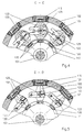
- FIG. 9 The partial sectional view of FIG. 9 (with removed Swivel housing cover) once again illustrates the holding jaws 104a, 104b of the transfer head 1 additionally awarded Degree of freedom and shows the transmission elements for the Transfer of an additional rotary movement, here to the outside Holding jaw 104b about the holding jaw axis A, wherein it can be seen that by an integral connection of the toothed segment 127 with the holding jaw 104b of this by meshing with the counter-toothed segment 129, a rotary movement about the holding jaw axis A can be awarded when the shaft is twisted 125, with which the counter-tooth segment 129 is firmly connected.
- the gap is a holding finger for each swivel housing 117 137 in a central radial plane B between the two holding jaws 104a, 104b, practically in plant or immediately adjacent provided for the respective article, here candy 205, the reliable support and handover of the candy 205 from the transfer head 1 to the successor device, here the stacking belt 301 of the stacking belt conveyor 3 is supported.
- FIG. 11a and 11b schematically the transfer of the individually wrapped candies (205) from the transfer head 1 for one Holding jaw pair shown schematically, in Fig. 11a for the formation of groups for upright packaging and in Fig. 11b for forming groups in a flat pack, in particular for Fig. 11a it is clear that the rotational movement of the holding jaws 104a, 104b about the holding jaw axis A in the area of the Transfer to the stacking belt conveyor 3, i.e. under superimposition the pivoting movement that the holding jaws 104a, 104b with the Execute swivel housing 117, done.
- the thrust bearing 304 has an insertion slope 304a and the holding finger 137 stands if necessary, ready to support the handover process.
- Group A, B is then moved by driver 302 along the counter holder in a packing compartment 305 thus formed promoted away.
Landscapes
- Engineering & Computer Science (AREA)
- Mechanical Engineering (AREA)
- Specific Conveyance Elements (AREA)
Claims (15)
- Dispositif de transport rotatif pour le transfert d'articles en petits morceaux pour des machines d'emballage, comprenant un logement de base (102) pouvant tourner autour d'un axe fixe (101) et portant plusieurs paires de mâchoires de maintien (104) servant à tenir l'objet entre des mâchoires de maintien (104a, 104b) d'une paire de mâchoires de maintien (104) qui peuvent se déplacer dans des sens opposés le long d'un axe (A) des mâchoires de maintien, chaque paire de mâchoires de maintien (104) pouvant pivoter autour d'un axe de pivotement (103) s'étendant de manière essentiellement parallèle à l'axe fixe (101), et un dispositif de commande de déplacement pour les paires de mâchoires de maintien (104) étant prévu en liaison avec un dispositif à came de commande (109) fixe situé sur l'axe (101), caractérisé en ce qu'au moins une mâchoire de maintien (104a, 104b) de chaque paire de mâchoires de maintien (104) peut tourner, par rapport à l'axe de pivotement (103), autour de l'axe (A) des mâchoires de maintien.
- Dispositif de transport rotatif selon la revendication 1, caractérisé en ce que les mâchoires de maintien (104a, 104b) sont reliées à un segment denté (126, 127) d'une manière empêchant la rotation et un segment denté antagoniste (128, 129) du dispositif de commande de déplacement est enclenché par engrènement avec ce segment denté (126, 127).
- Dispositif de transport rotatif selon l'une des revendications 1 ou 2, caractérisé en ce que le logement de base (102) contient plusieurs logements pivotants (117) qui peuvent pivoter autour de l'axe de pivotement respectif (103) et dans lesquels est montée, sur chacun des deux côtés d'un plan radial (B) et de manière rotative autour de l'axe (A) des mâchoires de maintien, une mâchoire de maintien (104a, 104b) d'une paire de mâchoires de maintien (104).
- Dispositif de transport rotatif selon au moins une des revendications précédentes 1 à 3, caractérisé en ce que les mâchoires de maintien (104a, 104b) sont des corps cylindriques pourvus d'un segment denté solidaire (126, 127).
- Dispositif de transport rotatif selon au moins une des revendications précédentes 2 à 4, caractérisé en ce que, pour chaque paire de mâchoires de maintien (104), on prévoit une paire de segments dentés antagonistes (128, 129) situés à une distance axiale et enclenchés par engrènement avec les segments dentés (126, 127) de la paire de mâchoires de maintien (104), et les segments dentés antagonistes (128, 129) peuvent pivoter autour de l'axe de pivotement (103).
- Dispositif de transport rotatif selon au moins une des revendications précédentes 1 à 5, caractérisé en ce que l'axe de pivotement (103) est formé par un arbre (125) qui porte un segment denté antagoniste (129) d'une manière empêchant la rotation en vue de l'enclenchement avec le segment denté (127) de l'une des mâchoires de maintien (104b), tandis que l'autre segment denté antagoniste (128) destiné à s'enclencher avec le segment denté (126) de l'autre mâchoire de maintien (104a) de la paire de mâchoires de maintien (104) est relié d'une manière empêchant la rotation à une douille (124) entourant l'arbre (125) de manière concentrique.
- Dispositif de transport rotatif selon au moins une des revendications précédentes 1 à 6, caractérisé en ce que les mâchoires de maintien (104a, 104b) avec les segments dentés (126, 127) sont précontraintes dans le boítier pivotant (117) d'une manière élastique et permettant un déplacement axial.
- Dispositif de transport rotatif selon au moins une des revendications précédentes 1 à 7, caractérisé en ce que l'axe fixe (106) peut subir une rotation à 180° avec le dispositif à came de commande (109) du dispositif de commande de déplacement.
- Dispositif de transport rotatif selon au moins une des revendications précédentes 1 à 8, caractérisé en ce que le dispositif à came de commande (109) comprend plusieurs disques à came (110 à 114) reliés à l'axe fixe (106) d'une manière empêchant la rotation.
- Dispositif de transport rotatif selon au moins une des revendications précédentes 1 à 9, caractérisé en ce qu'un déplacement axial des mâchoires de maintien (104a, 104b) peut être commandé par un disque à came frontal (111, 112) respectif par le biais de leviers (121, 122) pivotants mais dont la position axiale sur l'arbre est fixe (125), et un mouvement rotatif, notamment un mouvement superposé au déplacement axial, des mâchoires de maintien (104a, 104b) autour de l'axe (A) des mâchoires de maintien peut être commandé, par une came à rainure (110a) et par le biais d'un levier de commande (132) monté de manière rotative, par un autre disque à came (110).
- Dispositif de transport rotatif selon au moins une des revendications précédentes 1 à 10, caractérisé en ce que, pour chaque logement pivotant (117), on prévoit un doigt de maintien (137) servant à l'appui de l'article (205), notamment lors du transfert de l'article (205) vers un dispositif (3) situé en aval.
- Dispositif de transport rotatif selon les revendications 3 et 11, caractérisé en ce que le doigt de maintien (137) est situé dans la région du plan radial (B).
- Dispositif de transport rotatif selon la revendication 12, caractérisé en ce que le doigt de maintien (137) peut être commandé par une came à rainure (135) et un galet de commande (139) par le biais d'un levier (138) monté de manière rotative, afin d'obtenir une synchronisation du mouvement avec le logement pivotant (117).
- Dispositif de transport rotatif selon au moins une des revendications précédentes 11 à 13, caractérisé en ce qu'un logement (141) pour les doigts de maintien prévu pour une commande du doigt de maintien (137) et tournant avec le logement de base (102) est situé en face du logement de base (102) contenant le dispositif de commande de déplacement pour les paires de mâchoires de maintien (104), le logement pivotant (17) se trouvant entre le logement de base (115) et le logement (141) pour les doigts de maintien.
- Dispositif de transport rotatif selon au moins une des revendications précédentes 1 à 14, caractérisé en ce que ce dispositif représente une tête de transfert (1) servant à recevoir des articles individuels emballés (205) d'une tête de saisie (2) située en amont et servant à transférer, notamment avec une rotation de 90° par rapport à une position de réception, les articles (205) vers un transporteur gerbeur (3) ordonnant les articles individuels (205) en groupes.
Applications Claiming Priority (2)
| Application Number | Priority Date | Filing Date | Title |
|---|---|---|---|
| DE19618510 | 1996-05-08 | ||
| DE19618510A DE19618510A1 (de) | 1996-05-08 | 1996-05-08 | Rotations-Transportvorrichtung zur Weitergabe von Gegenständen |
Publications (2)
| Publication Number | Publication Date |
|---|---|
| EP0835831A1 EP0835831A1 (fr) | 1998-04-15 |
| EP0835831B1 true EP0835831B1 (fr) | 1998-12-09 |
Family
ID=7793717
Family Applications (1)
| Application Number | Title | Priority Date | Filing Date |
|---|---|---|---|
| EP97107589A Expired - Lifetime EP0835831B1 (fr) | 1996-05-08 | 1997-05-07 | Dispositif de transport rotatif pour le transfert d'articles |
Country Status (2)
| Country | Link |
|---|---|
| EP (1) | EP0835831B1 (fr) |
| DE (2) | DE19618510A1 (fr) |
Families Citing this family (6)
| Publication number | Priority date | Publication date | Assignee | Title |
|---|---|---|---|---|
| JP4592166B2 (ja) * | 2000-10-04 | 2010-12-01 | 東洋自動機株式会社 | スパウト付き袋の搬送システム |
| DE10105448B4 (de) | 2001-02-07 | 2005-08-04 | Robert Bosch Gmbh | Vorrichtung zur Übergabe von Süßwarenstücken an eine Siegeleinrichtung |
| DE102005017329B4 (de) † | 2005-04-14 | 2014-10-16 | Theegarten-Pactec Gmbh & Co. Kg | Verfahren und Vorrichtung zum Verpacken kleinstückiger Artikel |
| DE102013200596A1 (de) * | 2013-01-16 | 2014-07-31 | Robert Bosch Gmbh | Vorrichtung und Verfahren zum Ausrichten eines Produktes in einer Verpackungsmaschine |
| CN104354906B (zh) * | 2014-11-13 | 2016-09-28 | 如皋市包装食品机械有限公司 | 一种高速双扭包装机的抓糖机械手结构 |
| CN113320744A (zh) * | 2021-07-09 | 2021-08-31 | 深圳市东盈讯达电子有限公司 | 一种蛋饺生产的转盘式高速移栽机 |
Citations (1)
| Publication number | Priority date | Publication date | Assignee | Title |
|---|---|---|---|---|
| EP0787667A1 (fr) * | 1996-02-05 | 1997-08-06 | AZIONARIA COSTRUZIONI MACCHINE AUTOMATICHE-A.C.M.A.-S.p.A. | Unité de manipulation de produits |
Family Cites Families (5)
| Publication number | Priority date | Publication date | Assignee | Title |
|---|---|---|---|---|
| DE1254082B (de) * | 1965-12-23 | 1967-11-09 | Schlosser & Co G M B H | Vorrichtung zum Stapeln von plattenfoermigen Formkoerpern in Hochkantstellung |
| GB1432371A (en) * | 1972-07-12 | 1976-04-14 | Rose Forgrove Ltd | Collation of articles |
| IT1159182B (it) * | 1982-06-23 | 1987-02-25 | Sasib Spa | Dispositivo trasferitore sequenzia le autocompensato in veloicita per convertire in rango trasversale una fila assialmente corrente di oggetti astiformi |
| IT1201605B (it) * | 1986-12-17 | 1989-02-02 | Gd Spa | Metodo e dispositivo per manipolare articoli |
| JP2875902B2 (ja) * | 1991-03-29 | 1999-03-31 | 日本たばこ産業株式会社 | 物品の移送・包装装置 |
-
1996
- 1996-05-08 DE DE19618510A patent/DE19618510A1/de not_active Ceased
-
1997
- 1997-05-07 EP EP97107589A patent/EP0835831B1/fr not_active Expired - Lifetime
- 1997-05-07 DE DE59700048T patent/DE59700048D1/de not_active Expired - Lifetime
Patent Citations (1)
| Publication number | Priority date | Publication date | Assignee | Title |
|---|---|---|---|---|
| EP0787667A1 (fr) * | 1996-02-05 | 1997-08-06 | AZIONARIA COSTRUZIONI MACCHINE AUTOMATICHE-A.C.M.A.-S.p.A. | Unité de manipulation de produits |
Also Published As
| Publication number | Publication date |
|---|---|
| EP0835831A1 (fr) | 1998-04-15 |
| DE59700048D1 (de) | 1999-01-21 |
| DE19618510A1 (de) | 1997-11-13 |
Similar Documents
| Publication | Publication Date | Title |
|---|---|---|
| EP0490084B1 (fr) | Dispositif pour l'emballage ou le déballage de récipients | |
| DE69614959T2 (de) | Vorrichtung und Verfahren zum Formieren von Produktgruppen,welche geordnet angeführt werden,mit vorgegeben Intervallen | |
| DE2526047A1 (de) | Umlaufende foerdervorrichtung an einer einwickelmaschine | |
| EP2282942B1 (fr) | Procédé d'emballage d'articles en petits morceaux, et machine d'emballage modulaire pour la mise en oeuvre du procédé | |
| EP2210813B2 (fr) | Procédé et dispositif destinés à l'emballage d'articles de petite taille | |
| EP0806358B1 (fr) | Méthode et dispositif de transfert d'articles | |
| EP2108589B1 (fr) | Procédé et dispositif de transfert de produits en petites pièces, notamment dotés d'un manche, sur un dispositif de transport longitudinal | |
| DE3915888C2 (de) | Vorrichtung zum Übergeben von Bonbons | |
| DE3013801C2 (fr) | ||
| EP0835831B1 (fr) | Dispositif de transport rotatif pour le transfert d'articles | |
| DE19616989C1 (de) | Vorrichtung zum Abtrennen und Aufnehmen von Bonbons | |
| EP1055620A1 (fr) | Dispositif pour prélever et/ou transporter des produits flexibles et plats | |
| DE60306238T2 (de) | Vorrichtung zum Übertragen von Gegenständen und eine mit dieser Vorrichtung versehene Einwickelmaschine | |
| DE69207045T2 (de) | Vorrichtung zum Überführen und Verpacken | |
| EP3263494B1 (fr) | Dispositif et procédé de convergence de plusieurs écoulements de produits parallèles en un seul écoulement de produit ou vice versa | |
| DE2934834C2 (de) | Vorrichtung zur Herstellung von Stangenpackungen aus vorzugsweise einzeln eingewickelten Bonbons o.ä. Süßwarenstücken. | |
| EP1357065B1 (fr) | Dispositif et procédé d'empilage de petits objets | |
| DE2329534A1 (de) | Vorrichtung zum einwickeln von bonbons oder aehnlichen kleinteilen | |
| EP0806385A1 (fr) | Méthode et dispositif de transfert pour délivrer des groupes d'objets d'un transporteur à bande d'empilage | |
| DD228230A5 (de) | Maschine zum verpacken und gruppieren von produkten | |
| EP0438763B1 (fr) | Machine d'emballage des cigarettes | |
| EP0756994B1 (fr) | Machine d'emballage pour introduire ou enlever des groupes de bouteilles ou récipients similaires dans ou hors des caisses pour bouteilles ou emballages similaires | |
| DE10309082A1 (de) | Vorrichtung zum Einwickeln von Bonbons in Verpackungshüllen | |
| EP1714877B1 (fr) | Dispositif et procédé d'alignement d'articles | |
| DE3705913A1 (de) | Vorrichtung zum handhaben von kegelfoermigen suesswarenstuecken |
Legal Events
| Date | Code | Title | Description |
|---|---|---|---|
| GRAG | Despatch of communication of intention to grant |
Free format text: ORIGINAL CODE: EPIDOS AGRA |
|
| PUAI | Public reference made under article 153(3) epc to a published international application that has entered the european phase |
Free format text: ORIGINAL CODE: 0009012 |
|
| 17P | Request for examination filed |
Effective date: 19970606 |
|
| AK | Designated contracting states |
Kind code of ref document: A1 Designated state(s): DE GB IT NL |
|
| GRAG | Despatch of communication of intention to grant |
Free format text: ORIGINAL CODE: EPIDOS AGRA |
|
| GRAH | Despatch of communication of intention to grant a patent |
Free format text: ORIGINAL CODE: EPIDOS IGRA |
|
| GRAH | Despatch of communication of intention to grant a patent |
Free format text: ORIGINAL CODE: EPIDOS IGRA |
|
| GRAA | (expected) grant |
Free format text: ORIGINAL CODE: 0009210 |
|
| AK | Designated contracting states |
Kind code of ref document: B1 Designated state(s): DE GB IT NL |
|
| GBT | Gb: translation of ep patent filed (gb section 77(6)(a)/1977) |
Effective date: 19981210 |
|
| REF | Corresponds to: |
Ref document number: 59700048 Country of ref document: DE Date of ref document: 19990121 |
|
| ITF | It: translation for a ep patent filed | ||
| PLBE | No opposition filed within time limit |
Free format text: ORIGINAL CODE: 0009261 |
|
| STAA | Information on the status of an ep patent application or granted ep patent |
Free format text: STATUS: NO OPPOSITION FILED WITHIN TIME LIMIT |
|
| 26N | No opposition filed | ||
| REG | Reference to a national code |
Ref country code: GB Ref legal event code: IF02 |
|
| PGFP | Annual fee paid to national office [announced via postgrant information from national office to epo] |
Ref country code: GB Payment date: 20150518 Year of fee payment: 19 Ref country code: DE Payment date: 20150527 Year of fee payment: 19 |
|
| PGFP | Annual fee paid to national office [announced via postgrant information from national office to epo] |
Ref country code: IT Payment date: 20150527 Year of fee payment: 19 Ref country code: NL Payment date: 20150516 Year of fee payment: 19 |
|
| REG | Reference to a national code |
Ref country code: DE Ref legal event code: R119 Ref document number: 59700048 Country of ref document: DE |
|
| REG | Reference to a national code |
Ref country code: NL Ref legal event code: MM Effective date: 20160601 |
|
| GBPC | Gb: european patent ceased through non-payment of renewal fee |
Effective date: 20160507 |
|
| PG25 | Lapsed in a contracting state [announced via postgrant information from national office to epo] |
Ref country code: NL Free format text: LAPSE BECAUSE OF NON-PAYMENT OF DUE FEES Effective date: 20160601 Ref country code: IT Free format text: LAPSE BECAUSE OF NON-PAYMENT OF DUE FEES Effective date: 20160507 |
|
| PG25 | Lapsed in a contracting state [announced via postgrant information from national office to epo] |
Ref country code: DE Free format text: LAPSE BECAUSE OF NON-PAYMENT OF DUE FEES Effective date: 20161201 |
|
| PG25 | Lapsed in a contracting state [announced via postgrant information from national office to epo] |
Ref country code: GB Free format text: LAPSE BECAUSE OF NON-PAYMENT OF DUE FEES Effective date: 20160507 |