EP2282942B1 - Procédé d'emballage d'articles en petits morceaux, et machine d'emballage modulaire pour la mise en oeuvre du procédé - Google Patents
Procédé d'emballage d'articles en petits morceaux, et machine d'emballage modulaire pour la mise en oeuvre du procédé Download PDFInfo
- Publication number
- EP2282942B1 EP2282942B1 EP09733106.0A EP09733106A EP2282942B1 EP 2282942 B1 EP2282942 B1 EP 2282942B1 EP 09733106 A EP09733106 A EP 09733106A EP 2282942 B1 EP2282942 B1 EP 2282942B1
- Authority
- EP
- European Patent Office
- Prior art keywords
- article
- packaging
- station
- gripper
- head
- Prior art date
- Legal status (The legal status is an assumption and is not a legal conclusion. Google has not performed a legal analysis and makes no representation as to the accuracy of the status listed.)
- Not-in-force
Links
- 238000004806 packaging method and process Methods 0.000 title claims description 272
- 238000000034 method Methods 0.000 title claims description 54
- 238000012856 packing Methods 0.000 claims description 87
- 239000005022 packaging material Substances 0.000 claims description 58
- 238000012858 packaging process Methods 0.000 claims description 17
- 230000008569 process Effects 0.000 claims description 17
- 238000012546 transfer Methods 0.000 claims description 14
- 238000013461 design Methods 0.000 claims description 13
- 235000019219 chocolate Nutrition 0.000 claims description 8
- 230000008859 change Effects 0.000 claims description 7
- 235000009508 confectionery Nutrition 0.000 claims description 7
- 239000000463 material Substances 0.000 claims description 7
- 238000011144 upstream manufacturing Methods 0.000 claims description 5
- 239000011248 coating agent Substances 0.000 claims description 4
- 238000000576 coating method Methods 0.000 claims description 4
- 238000003780 insertion Methods 0.000 claims description 3
- 230000037431 insertion Effects 0.000 claims description 3
- 230000000712 assembly Effects 0.000 claims 6
- 238000000429 assembly Methods 0.000 claims 6
- 244000299461 Theobroma cacao Species 0.000 claims 4
- 238000007599 discharging Methods 0.000 claims 3
- 230000008878 coupling Effects 0.000 claims 1
- 238000010168 coupling process Methods 0.000 claims 1
- 238000005859 coupling reaction Methods 0.000 claims 1
- 230000002093 peripheral effect Effects 0.000 claims 1
- 238000000926 separation method Methods 0.000 description 19
- 230000010355 oscillation Effects 0.000 description 5
- 230000015572 biosynthetic process Effects 0.000 description 4
- 235000011475 lollipops Nutrition 0.000 description 3
- 238000004519 manufacturing process Methods 0.000 description 3
- 238000004904 shortening Methods 0.000 description 3
- 238000003860 storage Methods 0.000 description 3
- 230000008901 benefit Effects 0.000 description 2
- 235000013736 caramel Nutrition 0.000 description 2
- 238000009795 derivation Methods 0.000 description 2
- 238000000605 extraction Methods 0.000 description 2
- 239000003292 glue Substances 0.000 description 2
- 238000007654 immersion Methods 0.000 description 2
- 238000009825 accumulation Methods 0.000 description 1
- 230000004913 activation Effects 0.000 description 1
- 230000006978 adaptation Effects 0.000 description 1
- 238000013459 approach Methods 0.000 description 1
- 238000010276 construction Methods 0.000 description 1
- 238000010924 continuous production Methods 0.000 description 1
- 238000000151 deposition Methods 0.000 description 1
- 239000011888 foil Substances 0.000 description 1
- 238000009434 installation Methods 0.000 description 1
- 210000000056 organ Anatomy 0.000 description 1
- 230000003534 oscillatory effect Effects 0.000 description 1
- 238000002360 preparation method Methods 0.000 description 1
- 238000012545 processing Methods 0.000 description 1
- 230000002035 prolonged effect Effects 0.000 description 1
- 239000000725 suspension Substances 0.000 description 1
- 238000012549 training Methods 0.000 description 1
- 230000007704 transition Effects 0.000 description 1
Images








Classifications
-
- B—PERFORMING OPERATIONS; TRANSPORTING
- B65—CONVEYING; PACKING; STORING; HANDLING THIN OR FILAMENTARY MATERIAL
- B65B—MACHINES, APPARATUS OR DEVICES FOR, OR METHODS OF, PACKAGING ARTICLES OR MATERIALS; UNPACKING
- B65B59/00—Arrangements to enable machines to handle articles of different sizes, to produce packages of different sizes, to vary the contents of packages, to handle different types of packaging material, or to give access for cleaning or maintenance purposes
- B65B59/04—Machines constructed with readily-detachable units or assemblies, e.g. to facilitate maintenance
-
- B—PERFORMING OPERATIONS; TRANSPORTING
- B65—CONVEYING; PACKING; STORING; HANDLING THIN OR FILAMENTARY MATERIAL
- B65B—MACHINES, APPARATUS OR DEVICES FOR, OR METHODS OF, PACKAGING ARTICLES OR MATERIALS; UNPACKING
- B65B11/00—Wrapping, e.g. partially or wholly enclosing, articles or quantities of material, in strips, sheets or blanks, of flexible material
- B65B11/06—Wrapping articles, or quantities of material, by conveying wrapper and contents in common defined paths
- B65B11/28—Wrapping articles, or quantities of material, by conveying wrapper and contents in common defined paths in a curved path, e.g. on rotary tables or turrets
- B65B11/30—Wrapping articles, or quantities of material, by conveying wrapper and contents in common defined paths in a curved path, e.g. on rotary tables or turrets to fold the wrappers in tubular form about contents
-
- B—PERFORMING OPERATIONS; TRANSPORTING
- B65—CONVEYING; PACKING; STORING; HANDLING THIN OR FILAMENTARY MATERIAL
- B65B—MACHINES, APPARATUS OR DEVICES FOR, OR METHODS OF, PACKAGING ARTICLES OR MATERIALS; UNPACKING
- B65B11/00—Wrapping, e.g. partially or wholly enclosing, articles or quantities of material, in strips, sheets or blanks, of flexible material
- B65B11/06—Wrapping articles, or quantities of material, by conveying wrapper and contents in common defined paths
- B65B11/28—Wrapping articles, or quantities of material, by conveying wrapper and contents in common defined paths in a curved path, e.g. on rotary tables or turrets
- B65B11/30—Wrapping articles, or quantities of material, by conveying wrapper and contents in common defined paths in a curved path, e.g. on rotary tables or turrets to fold the wrappers in tubular form about contents
- B65B11/32—Wrapping articles, or quantities of material, by conveying wrapper and contents in common defined paths in a curved path, e.g. on rotary tables or turrets to fold the wrappers in tubular form about contents and then to form closing folds of similar form at opposite ends of the tube
-
- B—PERFORMING OPERATIONS; TRANSPORTING
- B65—CONVEYING; PACKING; STORING; HANDLING THIN OR FILAMENTARY MATERIAL
- B65B—MACHINES, APPARATUS OR DEVICES FOR, OR METHODS OF, PACKAGING ARTICLES OR MATERIALS; UNPACKING
- B65B11/00—Wrapping, e.g. partially or wholly enclosing, articles or quantities of material, in strips, sheets or blanks, of flexible material
- B65B11/06—Wrapping articles, or quantities of material, by conveying wrapper and contents in common defined paths
- B65B11/28—Wrapping articles, or quantities of material, by conveying wrapper and contents in common defined paths in a curved path, e.g. on rotary tables or turrets
- B65B11/30—Wrapping articles, or quantities of material, by conveying wrapper and contents in common defined paths in a curved path, e.g. on rotary tables or turrets to fold the wrappers in tubular form about contents
- B65B11/34—Wrapping articles, or quantities of material, by conveying wrapper and contents in common defined paths in a curved path, e.g. on rotary tables or turrets to fold the wrappers in tubular form about contents the ends of the tube being subsequently twisted
-
- B—PERFORMING OPERATIONS; TRANSPORTING
- B65—CONVEYING; PACKING; STORING; HANDLING THIN OR FILAMENTARY MATERIAL
- B65B—MACHINES, APPARATUS OR DEVICES FOR, OR METHODS OF, PACKAGING ARTICLES OR MATERIALS; UNPACKING
- B65B25/00—Packaging other articles presenting special problems
- B65B25/005—Packaging other articles presenting special problems packaging of confectionery
-
- B—PERFORMING OPERATIONS; TRANSPORTING
- B65—CONVEYING; PACKING; STORING; HANDLING THIN OR FILAMENTARY MATERIAL
- B65B—MACHINES, APPARATUS OR DEVICES FOR, OR METHODS OF, PACKAGING ARTICLES OR MATERIALS; UNPACKING
- B65B35/00—Supplying, feeding, arranging or orientating articles to be packaged
- B65B35/06—Separating single articles from loose masses of articles
- B65B35/08—Separating single articles from loose masses of articles using pocketed conveyors
Definitions
- the present invention relates to a method for packaging small articles, in particular pralines or caramels with a chocolate coating, in a continuous mode of operation and by means of a packaging machine with a modular structure and a packaging machine with which the aforementioned method can be carried out.
- the packaging of small pieces of confectionery has long been carried out in the field of higher work performance according to the so-called continuous working principle, i.e. with packaging machines that are provided with a plurality of rotating heads (workstations) for product pick-up, transfer and packaging of the products, so that the articles can be processed in a continuous process and with high performance depending on the product type and type of wrapping (packaging type) as well as other boundary conditions with up to 1200 cycles per minute can be packed.
- the invention is therefore based on the object of eliminating the aforementioned disadvantages and of creating a method and a packaging machine, in particular for carrying out the method, which make it possible to achieve a previously unachievable diversity in terms of the processable product formats and sizes as well as the types of wrapping (folding types). , also in combination with each other and in connection with different feed and separation systems with high variability of the orientation of the articles within the packaging process, so that such a method and such a packaging machine with sufficient performance is of greater utility for the user than is the case with previous systems due to the rigid design and interlinking of the article-carrying packaging devices within the packaging machine is the case.
- this object is achieved by a method according to claim 1 and a packaging machine according to claim 14.
- the method according to the invention and the modular packaging machine according to the invention differ significantly from previously known systems and devices in that not only feed or discharge systems are modularly connected to different ones Packaging tasks are adaptable or wrapping-oriented associated stations within the packaging station and with regard to the packing head and the packaging organs that work with it can be modified, but that the removal wheel and / or the article gripper station and / or the packaging station with the packing head and the associated wrapping devices are interchangeable on a machine frame the packaging machine and can be flexibly combined with reference to the central, stationary axis to take into account different article types, article orientations and packaging types, in particular wrap types (claim 14).
- At least one of the article-carrying packaging devices is itself in the In the present case, preferably a removal wheel or an article gripper head rotatable about the central axis or a downstream packing head (in addition to the additional devices that are already known to be modularly assignable to this) are interchangeably received on a machine frame.
- a removal wheel or an article gripper head rotatable about the central axis or a downstream packing head (in addition to the additional devices that are already known to be modularly assignable to this) are interchangeably received on a machine frame.
- These are designed as independent modules depending on the desired product orientation within the packaging process or the design of the packaging machine as a two- or three-head machine or with different packing heads and packaging elements assigned to them, such as a turning station or folding station.
- the packaging machine can thus be quickly adapted to various packaging tasks, product types, types of wrapping and user requirements in a modular manner.
- packaging processes with a wide variety of product feed and separation as well as variable product orientation within the packaging machine and largely free choice of the type of packaging (type of wrapping) can be carried out according to user requirements with such a modular packaging machine with continuous operation.
- the required supply / separation and packaging devices are put together in an article-oriented manner and the article-carrying packaging devices are assigned to the central axis and the associated article gripper station.
- more complicated types of wrapping and packaging, especially combined wrapping, such as e.g. Folding and twisting wraps on an article (bag folding) can be produced very productively for the first time on a continuous and high-performance basis, preferably working in the middle-class range.
- the method according to the invention and the packaging machine according to the invention make it possible not only to change the format, but also to change the type of folding to an expanded extent.
- This means that new, high-quality types of impact can be used can be implemented in a continuous working method, such as, for example, "top twist” (twist fold on the top of the product, fold fold on one side of the bottom).
- work stations such as removal heads and gripper heads, i.e. for example a removal wheel and the article gripper head (which rotates around the central axis) can also be exchanged according to the invention, and
- product orientations can also be variably designed when the article is recorded or when it passes through the packaging machine.
- the packaging method according to the invention and the packaging machine according to the invention which is preferably provided for its implementation, due to the modular character of the article-carrying packaging device itself (as such, in the context of the present application, primarily a removal wheel (if present) receiving the articles from a feed and / or separating device is , an article gripper head that can be rotated around a central main axis of the packaging machine (which may also function as a removal wheel) and the packing head can be exchanged, so that in addition to changing feed and separation units (e.g.
- workstations such as removal heads and gripper heads are also interchangeable in order to change product orientations within the packaging process as the article passes through the packaging machine er.
- the invention is particularly intended for the packaging of delicate chocolate-coated confectionery items, e.g. double turning, top twist, bag folding (sachet), stanoling and special folding can be realized with high packaging performance, preferably in the middle class range of up to 800 work cycles per minute.
- the invention is not limited to such chocolate products.
- a conveying device for the provision of articles located in receiving pockets of a separating plate, preferably a feed ring of the same, in a movement path of a holding jaw gripper device of a removal station, which e.g. a gripper wheel in a three-head packaging machine or an article gripper head of a gripper station in a two-head packaging machine.
- This outfeed device preferably contains a punch device with at least one lower punch wheel and a plurality (preferably of three) of vertically and circumferentially movable lower punches in connection with a special lower punch gear, which subsequently lift the articles out of the receiving pockets of the separating wheel, possibly while holding the article an upper ram that can be moved by means of an upper ram gear so that the article in question can be gripped with separation from the separating plate by pairs of holding jaws of a device arranged below for removing or receiving the articles in the packaging machine.
- the lower rams which are always vertically oriented and articulated in the lower ram gear, can be mounted eccentrically, preferably adjustable, so that an adjustable, variable stroke change, in particular an increase in stroke, is possible compared to a coaxial mounting of the lower ram on the associated movement gear element.
- a special folding process and a folding station designed for this purpose with a corresponding folding head is provided, the folding process being characterized in that for a fold, in particular for a first fold, following a U-shaped, open wrapping of the article
- a material relaxation releasing, material relaxation pre-folding (or breaking) is carried out on this packaging material section before a complete, preferably with a very thin folding element, the fold is applied to the article.
- This material tension-reducing pre-folding with subsequent final folding is preferably carried out at least once, but preferably twice within a complete folding process.
- Preferred embodiments of a corresponding folding process and a folding head preferably provided for carrying out such a wrapping process are set out in the other claims.
- folding forces can thus be minimized and the packaging material can be held securely at all times, so that a spring-back opening of the fold is also avoided.
- a turning station for the formation of turning envelopes, in particular for the handling of relatively large-sized products and e.g. for a "top twist" impact, whereby to compensate for the axial shortening of the packaging material when the rotary blades are screwed in, the rotary gripper can execute an axial oscillation movement which is derived in a cam-controlled manner.
- an adjusting device is provided for the effective stroke of the screwing-in process, made possible in particular by the adjustability of a start of the oscillating movement of the rotary gripper relative to an opening or closing time of the rotary gripper jaws of the rotary gripper.
- a second independent cam is preferably provided for the opening and closing movement, and a stroke setting for the axial movement of the rotary gripper is effected by an adjusting gear that allows a relative positioning of the control cam (preferably drum cam) for the oscillating movement of the rotary gripper to the position of the closing and opening cam for controls the opening and closing movement of the rotary gripper jaws.
- Such a one Rotary station or such a rotary head can be used and used both in combination with the modular structure of the packaging machine and in other packaging machines which are not modular and which work according to the continuous operating principle.
- the continuously operating packaging machine allows the combination of turning and folding stations in the packaging station for the production of e.g. of top twist packaging.
- the packaging machine according to the invention is preferably provided with a central gear with corresponding control cams for deriving rotational and gripper jaw movements of the article gripper station rotating on the central axis of rotation, whereby the drive movements for the packaging station (packing head and associated folding and / or rotating stations) are preferably also provided by this central gear ) be derived.
- the supply and separation station which is connected upstream of the article-carrying packaging devices in the sense of the present application, is preferably mechanically connected to the "basic machine", but is individually driven separately.
- the modular design of the packaging machine also allows the transition to largely separate, independent control concepts for the individual packaging devices using independent servomotors. Also within the packaging equipment, for the control of the folding processes or mechanical-electrical hybrid drives (derivation of the movements of control cams and the use of micromotors) for a further individualization of the drive concept for the individual workstations and within the same for the derivation of product-oriented or control movements (e.g. for the Control of rotary grippers in a rotary station within the packaging station).
- a common control device (CPU) is preferably provided to control the individual individual drives and servomotors.
- the packaging method according to the invention and the packaging machine according to the invention also enable complicated packaging tasks, such as the packaging of lollipops, to be solved with high efficiency.
- the article gripper station deviating from the preferred exemplary embodiments of the present invention explained below, can have a structure such as, for example, from FIG EP 1 712 472 A1 is known to the applicant. This also applies to the other components, such as the separating plate or packing head or packing station.
- the exemplary embodiments of the invention explained below are both for continuously operating packaging machines with two article-carrying packaging devices, in which the article gripper station directly picks up the separated articles coming from a feed or separation system and forwards them in the same or a different orientation to a packaging station from which the packaged articles are conveyed away, or can be used for packaging machines with three or more article-carrying packaging devices, in which a removal wheel is used to pick up the articles from a feed or separation device and pass them on in the same or a different orientation to an article gripper station with an article gripper head , to which a packaging material is supplied, is provided in order to be transferred from this second head in the same or a different orientation of the articles together with the piece of packaging material to the packaging station .
- a delivery wheel can also be attached to the packaging station for the orderly depositing of the packaged articles on a discharge belt (web belt).
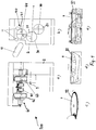
- Fig. 1a shows a schematic side view of a basic type of packaging machine 100 according to a first exemplary embodiment, only one packaging station 40 with a packaging head 41 and opposing rotating stations 42, 43 being shown here, as is used for the production of packaging in a double twist wrap (with two Rotary vane) is used.
- the lack of an extraction station (see extraction station 20 in Figure 1b ) or an article gripper station 30 (cf. Figure 1b ) should be in the Fig. 1a indicate that these article-carrying packaging devices are designed to be variable and optionally added to complete the packaging machine 100 (three-head packaging machine) or that only one article gripper station 30, rotatable around a central stationary axis of rotation 1, is additionally used when the Packaging machine 100 as a two-head packaging machine.
- Fig. 1a therefore illustrates the basic modular concept of the packaging machine 100.
- these heads can be exchanged in different configurations, in particular with regard to an orientation of the articles as they pass through the packaging machine 100 and can preferably merge the removal station 20 with the article gripper station 30 (two-head packaging machine) .
- an interchangeability of the packing head 41 within the packing station 40 is also provided.
- Figure 1b shows in principle and in a front view such a configuration of the "prototype" Fig. 1a as a three-head packaging machine with three article-carrying packaging devices (namely the removal station 20, the article gripper station 30 and the packaging station 40).
- a removal head 21, an article gripper head 31 and a package head 41 are provided accordingly and only indicated schematically here. Their direction of rotation is indicated by arrows in Figure 1b indicated.
- an article gripper station is used as a removal station or also as a removal device in a two-head packaging machine 30 with an article gripper head 31 and, in the event that the removal station 20 is part of a three-head packaging machine, as in FIG Figure 1b shown, denotes a removal wheel 21 which picks up articles from a feed and / or separating device 10.
- FIGS. 1c to 1e are examples of such feeding and separating devices 10 schematically as a plate feeder with separating plate 7 in FIG Figure 1c , Belt or chain feed with a linear feed device 8 in Fig. 1d or a strand feed device 9 in Fig. 1e shown.
- Such feed and separation devices are mechanically coupled to the packaging machine 100 depending on the product type and feed system and are driven by at least one decentralized, separate drive, as is conventional.
- the packaging machine 100 is characterized in its modular structure that a central axis 1 is fixed on a machine frame 2 of the packaging machine 100 about which an n-part work station, namely the article gripper station 30 with the article gripper head 31, can be rotated and to which a packaging material (not shown here) is also supplied from a packaging material supply device, also not shown here, in order to be applied to a relevant article and passed on with it to the packaging station 40.
- a packaging material (not shown here) is also supplied from a packaging material supply device, also not shown here, in order to be applied to a relevant article and passed on with it to the packaging station 40.
- the packing station 40 with the packing head 41 here equipped with opposite turning stations 42 and 43, is of course not limited to such an embodiment, but other folding stations or folding heads opposite to the packing head 41, or combinations of folding stations and turning stations, e.g. B.
- the packing head can also be modularly exchanged on the machine frame 2 in different configurations, e.g. B. depending on the size of the article to be packaged is provided.
- the axes between the packaging station 40 and the article gripper station 30 are offset from one another at an angle ⁇ of approximately 20 ° and the packaging station 40 is laterally offset above the article gripper station 30.
- This angular offset can, however, be changed within the framework of the overall design of the packaging machine 100, in particular selected within a range of approximately 10 ° to approximately 60 °.
- FIG. 1b Schematically, in Figure 1b further folding stations 11 or folding members, possibly assigned to the packing head 41, are shown as possible components of the packaging machine 100, which make it possible to realize further types of wrapping, such as stanoling.
- the removal station 20 here formed by a removal wheel 21, has a plurality of pairs of holding jaws, each pivotably mounted on the removal wheel 21, in order to pick up articles from one of the feed or separation devices and pass them on to the article gripper station 30, the article gripper head 31 of which also has corresponding pairs of holding jaws, mostly referred to in the context of the present application as pairs of gripper jaws.
- the packing head 41 of the packing station 40 has pairs of holding jaws for fixing the articles, without this being shown in more detail here. Special features of the present exemplary embodiments will be discussed in greater detail below. What is essential in the context of this exemplary embodiment is the exchangeable, i.e.
- the removal station 20 the article gripper station 30 and / or the packaging station 40, i.e. a removal wheel 21 and / or an article gripper head 31 and / or a packing head 41, adapted to an article type or an article orientation or a selected type of packaging (wrapping type), as will be explained in more detail below.
- the packing head can also have other configurations and be equipped, for example, with rotating folding shafts, with the article being transferred between the article gripper station and the packing head by means of expandable transfer stamps.
- the packing station 40 with the packing head 41 is rotatable about a second fixed axis (packing head axis) 44 and with 12 is in Figure 1b denotes a delivery device for the (in this case unordered) removal of packaged articles from the packaging machine 100.
- the controller depending on the desired product wrapping the corresponding holding elements (pairs of gripper jaws) can be selected depending on the type of article, so that such a packaging machine, which preferably works in the middle class range of up to approx. 800 products per minute, can be converted quickly by the manufacturer as well as by the user, even for small series with regard to the formats as well as the realizable types of wrapping and packaging types in great variability and diversity.
- the present packaging machine 100 for example, not only the turning station 42, 43 (or a folding station or two folding stations proposed there) can be changed depending on the type of wrapping on the packing head axis 44, or various units such as separating plates 7, belt or chain feeder 8 or strand feeder 9 can be provided as a feed or separation device 10 for the articles at the entry area of the packaging machine 100, but in particular the removal station 20 with the removal wheel 21 and / or the article gripper station 30 with the article gripper pot 31 and / or the packing station 40 with the packing head 41 and associated stations such as turning station 43 interchangeably mounted on the machine frame 2 of the packing machine 100 and with reference to the "fixed point" on the machine, namely the central axis 1 to take into account different article types, article orientations and wrapping types can be combined in a very flexible way.
- the packaging machine 10 provides the packing head as a fixed work station, so that only the article gripper station 30 (two-head) and / or the removal station 20 (removal head 21) is exchangeable on the machine frame 2.
- the article gripper station 30 two-head
- the removal station 20 removal head 21
- a central gear is preferably provided in connection with the central axis 1, from which the movements of the article gripper head 31 including those of the associated gripper jaws are derived by means of control cams, and it is preferably also a drive control for the packaging station 40 from this Central gear derived.
- the removal station 20 can also be cam-controlled with a drive derived from the central gear.
- the delivery device 12 is also driven in a decentralized manner.
- necessary movement controls within the article-carrying packaging devices 20, 30, 40, in particular in the area of the packaging station 40 possibly further motorized actuating means such as micromotors, possibly also as hybrid movement control devices in connection with cam-controlled elements, or else cam-controlled in a conventional manner respectively.
- the removal wheel 21 has the function of removing the articles from the feeding or separating device 10 for transfer to the article gripper head 31, whereby an orientation of the articles can also be changed for certain types of wrapping.
- the article gripper head 31 located on the central axis 1 is also changed for certain product orientations and, if necessary, an exchange of the packing head 41 is provided, in particular in connection with associated stations such as a folding station or turning stations 43.
- FIG. 1a and 1b shown packaging machine 100 with three article-carrying heads (removal wheel 21, article gripper head 31, packing head 41) in a two-head packaging machine (cf. Fig. 7 ), which is characterized by a very product-friendly design, and e.g. for the packaging of lollipops from the EP 1 712 472 A1 is known.
- a two-head packaging machine is preferably explained in connection with a separation principle, explained in more detail below, for picking up the articles from a separating plate 7 and transferring them directly to the article gripper head 31.
- a special removal wheel 20 is dispensed with.
- the modular character of the packaging machine 100 is also expressed in terms of the optional usability of further folding members or stations 11 arranged on the circumference of the packing head 41, which are suitable for special wraps, e.g. Stanoling can be provided, or additional functions such as tear-open aid, label dispenser and packaging closure aids (glue point) can be implemented.
- the dispensing device 12 also forms a separate modular unit with its own drive, preferably an orderly or one, as in FIG Figure 1b shown schematically, can be disordered article delivery.
- the articles are conveyed via an ejector in the packing head 41 onto a dispensing belt of the dispensing device 12.
- the articles are removed from the packing head 41 via a transfer wheel (not shown here) and deposited in a defined manner on a web belt of the conveying device 12.
- the separating plate 7 has a plurality of receiving pockets 12 on its outer circumference in a feeding ring 7a that is separate from an inner feeding area 7b and rotating in the same or opposite directions to this feeding area 7b, into which the articles 13, which are initially placed on the separating plate 7 in a disordered manner distributed and absorbed by rotational forces.
- the feed ring 7a rotates in the direction of the arrow (counterclockwise in Fig. 2 ).
- the inner feed area 7b, from which the disordered articles 13 are distributed into the receiving pockets 12, can rotate in the opposite direction, clockwise or in the same direction (clockwise), depending on the product and the process.
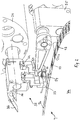
- a special discharge device 50 is provided in the present embodiment, which is designed and provided to lift each article 13 out of the receiving pockets 12 individually and in a movement path of the article gripper head 31 the article To provide gripper station 30 in order to be gripped by gripper jaws 33, pivotable in pairs about pivot axes 32, of article stations 35 of article gripper head 31 pivotable about pivot axes 34 parallel to central axis 1 and to be conveyed further in the direction of the arrow by rotating article gripper head 31 .
- the article gripper station 30 functions as a removal device or removal station, which directly picks up the article 13 from the separating plate 7 for transfer to a packing head 41, not shown here, with the further course of the article movement on and by means of the Article gripper head 31 is also supplied with a packaging material section (not shown here) and placed against the article 13.
- a pivotable packaging tongs 36 are a component of each article station 35 provided pivotably on the article gripper head 31, assigned to a pair of gripper jaws 33, 33.
- Fig. 2 the leading gripper station is not shown but is omitted in order to show the discharge device 50 with an upper punch 51 more clearly.
- the article 13 is gripped by the gripper jaws 33 at its end faces and taken over by the relevant pair of gripper jaws 33, 33.
- the discharge device 50 is described below with reference to FIG Figures 3 to 6 explained in more detail.
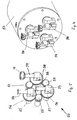
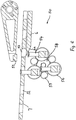
- a lower punch wheel 53 as the main component (cf. Fig. 4 ), the how Fig. 6 clarified, is arranged below the separating plate 7 in such a way that the eccentrically supported lower punch 54 of the lower punch wheel 53, in the present case there are three lower punches 54, alternately and depending on the spacing of the receiving pockets and the speed of rotation of the separating plate 7 in a constant vertical orientation ( s. Figures 4-6 ) dip into the receiving pockets 12 from below and lift the article 13 out of the receiving pockets 12 for transfer to the gripper jaw pairs 33, 33, as in particular Fig. 3 clarified.
- the upper ram 51 is used to secure the storage of the article 13 while it is being lifted out by the lower ram 54, the movement of which is ensured by an upper ram gear 55, not shown here.
- the articles 13 are first separated into the receiving pockets 12 within the separating plate 7 (perforated plate), the articles 13 being conveyed further in the circumferential direction by the separating plate 7 in the direction of the arrow (counterclockwise) and transported, i.e.
- the article gripper head 31 rotates, as indicated by arrows in FIG Fig. 2 and 3 shown, clockwise.
- the receiving pockets 12 of the separating table 7 are adapted to the shape of the article 13 and e.g. round, oval, square or rectangular. Products with a rectangular or oval basic configuration and base can be transported through the separating plate 7 either to the left (tangential) or transversely (radial) to the direction of movement.
- the articles 7 are of a rectangular configuration and are arranged in a radially oriented manner in the separating plate 7 or the receiving pockets 12, so that they are clamped by the gripper jaws 33, 33 over their length after being made available by the conveying device 50.
- the receiving pockets of the same are arranged in the tangential direction on the circumference or, as in the present case, for the transport with an article main axis transverse to the direction of movement, the receiving pockets are arranged in the radial direction, so that in the present case Embodiment of the Art. 13 are transferred to the article gripper head 31 transversely to its transport direction.
- the lower punch wheel 53 is provided in the present case with three lower punches 54, which are mounted and driven in the lower punch wheel 53 in such a way that they are constantly in a vertical position during an entire revolution of the lower punch wheel 53, ie with the punch surface facing upward are located.
- the lower punches 54 are each supported by an associated guide gear 56 by shafts 57, with each guide gear 56 having the same number of teeth as a centrally, stationary and frame-fixed arranged sun gear 58.
- a drivable intermediate gear 59 is supported on this for each guide gear 56, that the guide gear 56 drives in rotation.
- the intermediate gears 59 like the shafts 57, are mounted in the housing of the lower punch wheel 53.
- the number of teeth of the intermediate gears 59 is arbitrary.
- the lower punches 54 are preferably eccentrically connected to the shafts 57 or the respectively associated guide gear 56. However, the lower punches 54 can also have their point of articulation on the axis of the shafts 57 or in the middle of the guide gear 56 fixed to the shaft, as is the case in the present exemplary embodiment.
- An eccentric articulation of the lower punches 45 has the advantage that in this way the stroke that the lower punches 54 perform to lift the article 13 out of the receiving pocket 12 can be increased.
- a prolonged period of immersion of the lower punch 54 in a relevant receiving pocket 12 must be taken into account when designing the division of the receiving pockets 12 and when coordinating the rotational speeds of the feed ring 7a and lower punch wheel 53.
- the degree of eccentricity of the bearing of the lower ram 54 is preferably adjustable, so that the size of the stroke of the lower ram can also be variably adjusted over a wide range to match the size of the article 13 and the situation of the taking over removal or gripper wheel to equip the lower punch 54 with a different discharge stroke.
- the lower stamps 54 approach the receiving pockets 12 of the separating plate 7 on a circular path from below, with the support ring 6 being interrupted in the area of the arrangement of the lower stamping wheel 53 in order to provide space for the lower stamp 54 to pass freely into the respective receiving pocket 12 of the separating plate 7.
- conical outlet area 6a of the support ring 6 ensures that between the support ring 6 and the adjacent lower punch 54 only a narrow gap occurs, so that the article 13 is pushed from the support ring 6 onto the lower punch 54 via this gap, as Fig. 6 clarified.
- the mode of operation of the conveying device for transferring an article 13 from the separating plate 7 to the article gripper head 31 is as follows: At the beginning of an upward movement of the lower punch 54 in question, the upper punch 51 moves over an article-filled receiving pocket 12 of the separating plate 7, so that a closed chamber is formed which fixes the article 13 in question in a form-fitting manner. In the further course of the upward movement (cf. Fig. 3 ) the article 13 is clamped between the lower die 54 and the upper die 51 and thus held securely.
- the opened holding jaws, ie the gripper jaws 33 of the article gripper head 31, which in this case acts as a removal unit, move into a position opposite the side surfaces of the article 13. This takes place from the top side in connection with the rotation of the article gripper head 31 or an additional pivoting movement of the article station 35 about the axis 34.
- FIG Fig. 7 shows the possibility of a belt or chain feed 8 as a feed and separation device and illustrates how already with reference to FIG Fig. 1 explains, at the same time the angular offset between packing head 41 and gripper head 31.
- the arrows in FIG Fig. 7 the direction of movement of the longitudinal conveyor 8 and the article gripper station 30 and packaging station 40 are indicated.
- the linear feed device 8 (feed belt and / or chain) preferably has a storage belt (not shown here) and a delivery belt or delivery chain provided directly in the transfer area to the article gripper head 31, in which the articles 13 are placed at a discrete article spacing in accordance with the spacing of the gripper jaws 33 on the article gripper head 31 and taking into account the feed speed and the rotational speed of the gripper jaw pairs 33 of the gripper head 31 are isolated.
- a tape feed 8 to a two-head packaging machine 100 the articles are fed in here from a side which is opposite to that in a three-head packaging machine 100 shown below, ie in the illustration of FIG Fig. 7 from the right, while with the arrangement of an additional removal wheel 21 (three-head packaging machine, s. Figure 1b ) such a tape feed is provided from the left.
- the longitudinal conveyor 8 in Fig. 7 can optionally also be a chain feeder.
- a bag fold with a foldable wrapper at the bottom and a rotating wrapper at the top of the product can be provided, by appropriate design of the packaging station 40, as in Fig. 12 shown.
- FIG Figure 1b three article-carrying packaging devices, namely the removal station 20 with the removal wheel 21, which picks up articles from a feed and / or separation device 10, an article gripper station 30 with the article gripper head 31, which conveys the articles 13 picked up with the assignment of a piece of packaging material, and to a packing station 40 with a packing head 41 in which the article is packed.
- Changes to the article orientation in the packaging process are preferably provided in the removal station 20 and / or in the article gripper station 30, while the article orientation is generally not changed in the packing head 41, but should not be excluded.
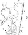
- FIG. 8 a first embodiment of the process sequence is explained schematically with the aid of the packaging of an article 13 in a double twist wrap, with sealed packaging "protected twist” or bag folds (sachet) being able to be carried out in a comparable manner and this method using a Removal wheel 21 is characterized as removal station 20, through which the articles 13 are picked up by a feed belt 8, consisting of accumulation belt 8a and separating belt 8b, without changing the orientation, and passed on to the article gripper head 31 in the article gripper station 30 without changing the article orientation.
- the process and packaging sequence, the packaging of hemispherical pralines 13 here in a double twist wrap, is shown in FIG Fig.
- the article gripper head 31 After picking up the articles 13 separated in the separating belt 8b and guiding them without changing direction in the removal wheel 21, they are transferred to the gripper jaws of the article gripper head 31, the article gripper head 31 at the same time the packaging material, ie a piece of packaging material 5 being fed and this to Article 13 is put on with the help of packaging tongs 36 (see Fig. 2 , Fig. 3 ). Before this, the article 13 is rotated by 90 °, as illustrated by the position of a bottom surface of the article 13 rotated between the article pick-up and the insertion of the packaging material piece 5.
- the piece of packaging material 5 is in turn formed in two layers with an inner fold 5a and an outer fold 5b, both pieces of packaging material pieces 5a, 5b adhere directly to one another (the piece of packaging material 5a is shortened in length compared to the piece of packaging material 5b) on the Article 13 introduced, as shown schematically in Fig. 8 indicated, but in the usual is conventional.
- a packaging material feed device is denoted by 4.
- a packaging material hose 13a is first formed, as shown schematically in FIG Fig. 8 is shown before turning stations not shown here, arranged on both sides of the packing head 41, ensure a double twist wrapping of the article, which is then dropped randomly onto a delivery belt of a discharge device 12 via an ejector not shown here.
- Fig. 9 shows a further exemplary embodiment for the packaging machine 100 or for the packaging method, the removal station in comparison to the exemplary embodiment according to FIG Fig. 8 is replaced, ie a removal wheel 21 'is used instead of the removal wheel 21 on the machine frame 2 of the packaging machine 100.
- This Removal wheel 21 ' now allows the article orientation to be changed on the way from picking up the article 13 from the separating belt 8b to the article gripper head 31 in which the piece of packaging material 5 is fed, wherein, as the arrows in FIG Fig.
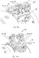
- FIG Fig. 9 A corresponding structure of an article unit 22 for an article 13 on the removal wheel 21 'is illustrated below with reference to FIG Fig. 11 explained., where the Figures 1a and 11b show a view from downstream and upstream of the article unit 22, respectively.
- FIG Fig. 9 a further rotation of the article 13 in the article gripper station 30 is made, in other words compared to the embodiment according to FIG Fig. 8 and Fig. 9
- Another article gripper head 31 ' is also used in this exemplary embodiment, such that the article orientation is rotated by 90 ° around a radial vertical axis of the corresponding pairs of gripper jaws. This is also indicated by the opposing arrows in the area of an article 13 of the article gripper head 30 '.
- the piece of packaging material 5 is placed on the article 13, held by means of the packaging tongs 36, not shown here, and transferred in this configuration to the packing head 41, the pairs of holding jaws holding the article constantly with a U-shaped piece of packaging material, ie clamp without direct contact with the article 13, but always from the outside with the interposition of the already U-shaped wrapped piece of packaging material 5.
- article 13 is transferred in a particularly gentle manner.
- the individual variants can be mixed and combined with one another in a corresponding manner, depending on the type of wrapping selected, so that the item 13 is in the "correct" position with regard to the packaging in the packing head 41 when it begins to be wrapped by a piece of packaging material.
- the removal wheel 21 preferably has the article units 22 which are rotatably mounted and controlled by cams, each article unit 22 having two opening levers 23, which each carry a rotatably mounted holding jaw 24.
- the holding jaws 24 can be pivoted through 90 ° by means of tie rods 25 so that they can be stopped. This pivoting movement is brought about by a cam-driven pivoting lever 26, so that a rotation of the article 13, which however can be locked, is brought about.
- Both a pivot axis of the pivot lever 26 and a pivot axis for the holding jaws 24 (which essentially coincides with an article transverse axis or runs parallel to this) therefore extend essentially axially parallel to a rotation axis of the removal wheel 21 '.
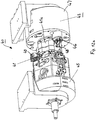
- a packing station 40 with a packing head 41, a turning station 43 and a instead of the second turning station 42 in FIG Fig. 1a provided folding station 45 explained.
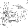
- a subsequent embodiment of the turning station 43 is explained.
- Rotary stations 43 are provided for the packaging of articles of smaller size and with correspondingly smaller rotary envelopes, in which a compensation for the shortening of the packaging material caused by rotation is compensated for by arranging a rotation axis of the rotation station inclined to a rotation axis of the associated package head 41, so that the associated Rotary gripper perform an oscillation (by inclination), ie a movement in the axial direction, due to the rotational movement of the rotary station.
- oscillation by inclination
- a movement in the axial direction due to the rotational movement of the rotary station.
- such a solution is inadequate when large items are packaged in a rotating envelope, e.g. in a diameter range between 30 mm and 40 mm, since a much larger axial travel for the rotary gripper in connection with the corresponding greater shortening of the packaging material when screwing in the rotary blades is required is.
- the larger design of the rotary station 43 with the axially movable and larger installation space-occupying rotary grippers 46 on a front side of a corresponding rotary head 47 also leads to a change in the packing head 41 such that it has concave sections 41a assigned to the corresponding rotary gripper position (in contrast to FIG usual circular-cylindrical design of an outer circumferential surface of the packing head 41) is designed to provide a sufficient To allow opening and closing movement of rotary gripper jaws 48 of rotary grippers 46 in a collision-free manner.
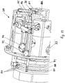
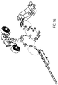
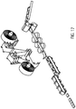
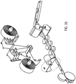
- An oscillating movement of the rotary gripper 46 is generated with a drum cam 70, which shows the rotary head 47 in greater detail Fig. 15 is shown, to which reference is made below.
- Circumferential rocker arms 71 are provided in this groove cam 70, which transfer the control movement generated by the drum cam 70 from the stationary drum cam 70 to the axially displaceable rotary grippers 46.
- the rotary grippers 46 preferably execute a maximum oscillation stroke with each revolution of the rotary head 47.
- this is adjustable, which could be achieved on the one hand by using different drum cams and / or predetermining the cam engagement position between cam and cam follower in the circumferential direction, but in the present case in a continuously adjustable manner by means of an adjustment device 75, by means of which an adjustment of the for the screwing process effective stroke is effected by shifting the oscillation start time relative to a closing time of the rotary gripper jaws 48 of the rotary gripper 46.
- This is achieved in that the drum cam 70 is rotated relative to a closing and opening cam 72.
- a prerequisite for this is a gear-related decoupling of the axial longitudinal or oscillating movement of the rotary gripper 46 from the closing and opening movement of the rotary gripper jaws 48.
- the closing and opening cam 72 drives a toothed segment 73, which is given a reciprocating pivoting movement.
- a toothed segment 73 With the toothed segment 73 is a spur gear 74 in engagement, which is rotatably mounted on a push rod 76 and is rotated in both directions of rotation.
- a cam sleeve 77 is firmly connected to the spur gear 74 and is supported against the rocker arm 71. In this way, the push rod 76 is moved axially and the rotary gripper jaws 48 of the rotary grippers are opened and closed.
- a folding station 45 is located opposite the turning station 43 on the other side of the packing head 41, in order to carry out types of wrapping such as sachet, top twist and diagonal letter folding on one side of the corresponding article.
- two opposite turning stations 43 can of course be used, or folding stations 45 can be arranged on both sides of the packing head in the case of an wrapping with diagonal letter folds on both sides.
- the structure of the folding station 45 and a special folding method are illustrated below with the aid of the bag folding Figures 13 and 14th explained.
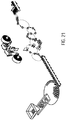
- Figure 12b pointed out shows a central section of the packaging station 40 in an enlarged view, with the turning station 43 and the turning jaws 48 of the associated turning gripper 46 on the right side as well as details of the packing head 41 with the holding jaw pairs 49 and further folding members of a folding head 78 in the folding station 45.
- Article 13 in the manner described above together with the piece of packaging material 5 (see Fig. 14 , in Figure 12b not shown) transferred from the article gripper head 31 to the packing head 41.
- the holding jaws 49 of the packing head 41 enclose the article 13, the in Figure 12b Packing material, not shown, is placed tightly around the article and clamped in the shape of a "U" together with article 13 (cf. Fig. 14 ).
- a starting position for the bag folding explained below is in Fig. 14 labeled "80".
- the folding station 45 In the front part of a packing head shaft there is the folding station 45 with the folding head 78 which carries out the folding processes for a bottom fold (bag bottom).
- the Rotating station 43 In the rear part of the packing head shaft is the Rotating station 43 with the rotating head 47, which forms a rotating wing on the top of the packaging and thus completes the packaging process.
- the packing head 41 is located in the middle between the rotating head 47 and the folding head 78.
- a folding process for the folding wrapping of the bottom of the sack begins with a protruding surface 5/1 of the U-shaped packaging material section facing the center of the packing head, through a pre-folder 79, followed by the same folding of the finished folder (burglar) 81, which folds in the same direction of movement.
- a packaging material neck 5/2 lying to the side of the finished folder 38 in the direction of movement is folded in by means of a side folder 82 and placed over the finished folder 81 or burglar 81.
- Downstream packaging material fold is then placed on a stationary folding plate as a side folder 83 over the previously produced folds.
- the side folder 83 which is relatively long in the circumferential direction, serves as a pressure piece for the folds that have already been produced and the packaging material surfaces arranged on the end face.
- the bottom fold of the sack is completed by a further pre-folder 84 and subsequent ready-made folder (burglar) 85 by pushing inwards over the second side folder 83 (pre-folder) or ready-made folds (ready-made folder 85).
- the pre-folder 84 serves to relieve and eliminate material tensions and ultimately a clean fold, which is completed by the finished folder 85.
- a folding step is implemented by means of two folding movements in the same direction, which leads to a particularly high-quality folding or leaves greater leeway with regard to the packaging materials used.
- packaging material flaps 5/3, 5/4 that are now still remaining are applied by the inner folder 86 and outer folder 87 stored in the packing head 41.
- the packaging material bottle 5/3, which lies upstream in the direction of movement, is folded in by the inner folder 86 and the packaging material bottle 5/4 lying ahead in the direction of movement is pressed by the outer folder 87 onto the packaging material bottle 5/3 placed by the inner folder 86.
- a bottom surface and the side surfaces of a sachet are thus completely enclosed by the packaging material.
- the protruding packaging tube is then gripped and the packaging process is completed by forming a rotary wing.
- the greater part of the period of time available over a predetermined angular range of the rotation of the packing head 41 is available for the bottom folding, while a smaller and shorter part is used for the formation of the rotary fold.
- these time relationships can be set and the packaging process can thus be optimized so that a sufficiently large angular range is available for performing the more complicated bottom fold, while the packing head has a relatively small angular range -Rotation is used to close the packaging with a twist wrap.
- Fig. 13 shows the folding head 78 again in an individual representation, with reference to the movement control of the aforementioned folding elements to an outer cam 88 which controls the movement of the first pre-folder 79, while the stationary outer cam 89 controls the finished folder (burglar) 81.
- the non-return forces required for external cam gears are applied by tension springs 90.
- a movement of the side folder 82 is controlled by a groove cam 91.
- a first four-bar gear 92 is provided for controlling the second pre-folder 84 and the second pre-folder (burglar) 85, which is controlled by a path of a spatial, stationary groove curve 93, while the second pre-folder 84 and the second ready-made folder (burglar) 85 by a Second four-bar linkage 94 are carried, the movement of which is controlled by a further path of the spatial groove cam 93.
- the machine concept also enables the packaging of very large products in the intended performance range in continuous operation for the first time.
- heated rotary grippers can also be used to seal packaging material in connection with rotary wraps and rotary stations, as is the subject of FIG EP 1 712 472 A1 which is here also made the subject of the disclosure of the present application by express reference.
- the modular machine structure in the area of article-carrying packaging devices in particular in the area of a removal station or an article gripper station, also leads to a high degree of variability with regard to possible wrapping shapes and article orientations within the packaging machine.
Landscapes
- Engineering & Computer Science (AREA)
- Mechanical Engineering (AREA)
- Basic Packing Technique (AREA)
Claims (30)
- Procédé pour emballer des articles en petits morceaux (13), en particulier des pralines ou des caramels avec un enrobage de chocolat, en fonctionnement continu par une machine d'emballage (100) de construction modulaire, la machine d'emballage (100) pouvant être commutée entre un fonctionnement avec deux têtes porteuses d'articles (31, 41) et avec trois ou plusieurs têtes porteuses d'articles (21, 31, 41), dans lequel, selon un type d'article et/ou une orientation d'article et/ou un type d'emballage, en particulier un type d'emballage enveloppant, les articles (13) sont amenés individuellement par un dispositif d'alimentation (10), qui peut être sélectionné parmi des systèmes de transport prédéterminés, à un processus d'emballage prédéterminé et sont guidés vers une station de préhension d'articles (30) qui peut être mise en rotation autour d'au moins un axe de rotation défini comme un axe central fixe (1), qui forme un poste de prélèvement (20) dans la machine d'emballage (100) avec deux têtes porteuses d'articles (31, 41) ou qui forme une roue de prélèvement (21) dans la machine d'emballage (100) avec trois têtes porteuses d'articles (21, 31) ou plus, 41) est montée en amont de ce poste de préhension d'article (30), une alimentation en matériau d'emballage (5) pour l'emballage de l'article (13) a également lieu vers ce poste de préhension d'article (30), puis le matériau d'emballage (5) avec l'article (13) est amené à un poste d'emballage (40) qui peut tourner au moins autour d'un axe de rotation fixe (44), le poste d'emballage (40) contenant une tête d'emballage (41) à laquelle sont ajoutés, en fonction du type d'emballage, des dispositifs d'emballage prédéterminés (42, 43), en particulier des postes de rotation et/ou de pliage, qui peuvent être sélectionnés parmi différents dispositifs, sont associés à la tête d'emballage (41) et les articles emballés (13) sont ensuite évacués, et dans lequel la roue de prélèvement (21) et/ou le poste de préhension d'articles (30) et/ou le poste d'emballage (40) avec la tête d'emballage (41) et les dispositifs d'emballage associés (42, 43) sont montés de manière interchangeable sur un châssis de machine (2) de la machine d'emballage (100) et sont combinés de manière flexible par rapport à l'axe central fixe (1) afin de prendre en compte différents types d'articles, orientations d'articles et types d'emballage, en particulier des types d'emballage.
- Procédé selon la revendication 1, dans lequel les articles (13) sont amenés individuellement par un dispositif de séparation des articles, en particulier un plateau de séparation (7), qui peut tourner autour d'au moins un axe de rotation, ou par un dispositif de transport longitudinal, en particulier un dispositif de transport à bande ou à chaîne (8) pour l'amenée d'articles individuels (13) ou au moyen d'un dispositif d'amenée de cordon de masse continu (9) en séparant les articles individuels du cordon de masse.
- Procédé selon au moins l'une des revendications 1 ou 2 précédentes, dans lequel les articles séparés (13) sont saisis et tournés autour d'au moins un axe, de préférence au moins un axe d'article ou un axe parallèle à un tel axe, avant d'être transférés à un autre dispositif, en particulier une station de préhension ou d'emballage d'articles (30).
- Procédé selon au moins l'une des revendications 1 à 3 précédentes, dans lequel les articles (13) sont tournés au moins une fois d'environ 90° entre la réception des articles d'un dispositif de séparation et/ou d'alimentation (10) et leur transfert à un autre dispositif.
- Procédé selon la revendication 3 ou 4, dans lequel l'axe, en particulier l'axe de l'article, s'étend sensiblement axialement parallèlement à un axe de rotation qui forme un centre de courbure d'un trajet de déplacement de l'article (13), et/ou sensiblement radialement perpendiculaire à cet axe de rotation et/ou sensiblement tangentiel au trajet de déplacement de l'article (13).
- Procédé selon au moins l'une des revendications 1 à 5 précédentes, dans lequel le processus d'emballage est réalisé sous alimentation à partir d'un premier sens d'alimentation par une machine d'emballage à trois têtes (100) avec une roue d'enlèvement (21), une tête de préhension d'articles (31) et une tête d'emballage (41) ou sous alimentation des articles (13) à partir d'un seconde sens d'alimentation opposé au premier sens d'alimentation par une machine à deux têtes avec une tête de préhension d'articles (31), à laquelle le matériau d'emballage est également fourni, et une tête d'emballage (41) en aval.
- Procédé selon au moins une des revendications 1 à 6 précédentes, dans lequel des modules de la machine d'emballage, en particulier un dispositif de séparation et/ou d'alimentation (10), une station de prélèvement (20), une station de préhension d'articles (30), une station d'emballage (40) ou un dispositif de prélèvement des articles sont commandés indépendamment les uns des autres, en particulier par des servomoteurs.
- Procédé selon au moins l'une des revendications 1 à 7 précédentes, dans lequel un poste de préhension d'articles (30) est entraîné par un engrenage central et un entraînement d'au moins un autre poste, en particulier le poste d'emballage (40), est dérivé de l'engrenage central, l'engrenage central contenant en particulier des cames de commande pour commander le mouvement de groupes, tels que des paires de pinces ou des mâchoires de maintien et des pinces d'emballage du poste de préhension d'articles et/ou d'un poste de prélèvement et/ou d'un poste d'emballage.
- Procédé selon la revendication 8, dans lequel des sous-stations de la station d'emballage (40), telles qu'une station de retournement (43) ou une paire de stations de retournement opposées (43) disposées des deux côtés d'une tête d'emballage (41) de la station d'emballage (40) ou une station de pliage (45) ou une paire de stations de pliage disposées des deux côtés de la tête d'emballage peuvent être entraînées conjointement par un engrenage central, dans lequel des sous-ensembles de la station de pliage (45) sont entraînés par des cames de commande d'un engrenage central.
- Procédé selon au moins une des revendications 1 à 9 précédentes, dans lequel des postes de travail, en particulier un dispositif d'alimentation (10), un poste de séparation et/ou d'enlèvement (20), un poste de préhension d'articles (30), un poste d'emballage (40) et/ou un dispositif d'enlèvement sont au moins partiellement commandés et/ou commandés individuellement par un dispositif de commande central (CPU) ou par des modules de commande et/ou d'entraînement décentralisés.
- Procédé selon au moins l'une des revendications 1 à 10 précédentes, dans lequel, à l'intérieur des dispositifs d'emballage, en particulier le poste de prélèvement et/ou le poste de préhension des articles et/ou le poste d'emballage, des micromoteurs sont prévus pour la commande du mouvement des ensembles des dispositifs d'emballage, tels que les pinces rotatives, les plieuses ou les paires de pinces ou les mâchoires de maintien.
- Procédé selon au moins une des revendications précédentes 1 à 11, dans lequel les dispositifs d'emballage sont entraînés et commandés par un mélange d'éléments de transmission, tels qu'un engrenage central avec des cames de commande qui sont balayées par des suiveurs de came, et des servomoteurs et/ou des micromoteurs sont prévus à l'intérieur des dispositifs d'emballage pour commander le mouvement d'ensembles, tels que des pinces rotatives, des plieuses ou des paires de pinces ou de mâchoires de maintien.
- Procédé selon au moins l'une des revendications 1 à 12 précédentes, dans lequel une commande d'entraînement d'ensembles périphériques, tels qu'un dispositif d'alimentation, un dispositif de séparation ou un poste d'évacuation sont entraînés par des servomoteurs, tandis qu'au moins le poste de préhension d'articles est entraîné par un engrenage central, et/ou des sous-stations du poste d'emballage, telles qu'un poste de retournement ou un poste de pliage sont entraînées/actionnées au moins partiellement par des servomoteurs, en particulier en liaison avec une commande mécanique ou par micromoteur d'ensembles de ces sous-stations.
- Machine d'emballage (100) de construction modulaire pour l'emballage en continu de petits objets, en particulier de chocolats ou de caramels avec un enrobage de chocolat, la machine d'emballage (100) pouvant être commutée entre le fonctionnement avec deux têtes porteuses d'objets (31, 41) et avec trois ou plusieurs têtes porteuses d'objets (21, 31, 41), avec un bâti de machine (2) et plusieurs dispositifs d'emballage porteuses d'objets (20, 30, 40) montés sur le bâti de machine (2), en particulier pour la mise en oeuvre du procédé selon au moins l'une des revendications 1 à 13 précédentes, dans lequel un axe central fixe (1) est fixé au bâti de la machine (2) en tant qu'axe de rotation d'un poste de préhension d'article (30), qui forme un poste de prélèvement (20) dans la machine d'emballage (100) avec deux têtes porteuses d'article (31, 41), ou qui forme une roue de prélèvement (21) dans la machine d'emballage (100) avec trois ou plusieurs têtes porteuses d'article (21), 31, 41) est placé en amont du poste de préhension d'articles (30), et auquel est également associée une réserve de matériau d'emballage (5) pour l'emballage de l'article (13), et un dispositif de séparation et/ou d'alimentation (10) est associé en tant que module au poste de préhension d'articles (30) et un poste d'emballage (40) pouvant tourner autour d'un axe de rotation fixe (44) et comportant des dispositifs d'enveloppement sélectionnables (42, 43) est placé en aval du poste de préhension d'articles (30), et dans lequel la roue de prélèvement (21) et/ou le poste de préhension d'article (30) et/ou le poste d'emballage (40) avec la tête d'emballage (41) et les dispositifs d'emballage associés (42, 43) sont montés de manière interchangeable sur le châssis de machine (2) de la machine d'emballage (100) et peuvent être combinés de manière flexible par rapport à l'axe central fixe (1) pour tenir compte des différents types d'articles, des orientations des articles et des types d'emballage, en particulier des types d'emballage.
- Machine d'emballage selon la revendication 14, dans laquelle les dispositifs d'emballage porteurs d'articles sont une roue de prélèvement (21) d'un poste de prélèvement (20), une tête de préhension d'articles (31) d'un poste de préhension d'articles (30) ou une tête d'emballage (41) d'un poste d'emballage (40), en particulier au moins une autre tête porteuse d'articles, en particulier la roue de prélèvement (20) et/ou la tête d'emballage (41), est associée à la tête de préhension d'articles (31).
- Machine d'emballage d'au moins une des revendications précédentes 14 à 15, comprenant un dispositif de séparation et/ou d'alimentation comme module séparé, de préférence avec un dispositif d'entraînement indépendant et séparé, tel qu'un servomoteur.
- Machine d'emballage selon au moins l'une des revendications précédentes 14 à 16, dans laquelle les objets (13) sont amenés individuellement par un dispositif de séparation des objets, en particulier un plateau de séparation (7), qui peut tourner autour d'au moins un axe de rotation, ou par un dispositif de transport longitudinal, en particulier un dispositif de transport à bande ou à chaîne (8) pour l'amenée d'objets individuels (13) ou au moyen d'un dispositif d'amenée de cordon de masse continu (9) avec séparation des objets individuels du cordon de masse.
- Machine d'emballage selon la revendication 17, dans laquelle le dispositif de séparation et d'alimentation (10) est un dispositif de transport à bande ou à chaîne (8), en particulier avec une bande d'accumulation pour l'accumulation d'articles, et une bande de séparation en aval de la bande d'accumulation, en particulier le dispositif de séparation et d'alimentation (10) comprend un brin de masse de caramel mou (9).
- Machine d'emballage selon au moins une des revendications précédentes 14 à 18, dans laquelle le dispositif d'alimentation (10) est couplé mécaniquement aux dispositifs d'emballage (20, 30) portant les articles ou peut être entraîné et commandé séparément et indépendamment de l'entraînement des dispositifs d'emballage, en particulier par un dispositif d'entraînement décentralisé.
- Machine d'emballage selon au moins une des revendications 14 à 19 précédentes, dans laquelle le poste de préhension d'articles (30) présente une tête de préhension d'articles (31) et, en particulier de manière pivotante, des paires de mâchoires de préhension (33, 33) montées sur celle-ci, et des flans de matériau d'emballage sont amenés à la tête de préhension d'articles (31), et/ou un dispositif d'alimentation en articles (10) est amené à la tête de préhension d'articles (31), en particulier un dispositif d'alimentation linéaire à courroie ou à chaîne (8) ou une plaque de séparation (7) tournant autour d'un axe de rotation sensiblement vertical avec des poches de réception (12) disposées sur la périphérie pour recevoir des articles (13) individuellement, en particulier sur leur longueur dans une disposition radiale, ou un dispositif d'alimentation massique en torons (9).
- Machine d'emballage selon au moins une des revendications précédentes 14 à 20, dans laquelle la tête de préhension d'article (31) présente des paires de mâchoires de préhension (33, 33) en tant qu'unités de prélèvement avec des pinces de matériau d'emballage (36) qui leur sont affectées pour l'affectation et le transfert commun d'un article (13) avec un morceau de matériau d'emballage à la tête d'emballage (41) située en aval.
- Machine d'emballage selon au moins l'une des revendications précédentes 14 à 21, dans laquelle la tête de préhension d'article (31), en particulier pour tenir compte de différentes orientations d'article dans le dispositif d'alimentation, est montée de manière interchangeable sur l'axe de rotation central fixe (1), en particulier en fonction du type d'article et/ou de l'orientation d'article et/ou du type d'emballage d'un poste de préhension d'article (30) reçu sur un axe central de la machine (1), un dispositif d'alimentation prédéterminé (10) et/ou une tête de préhension prédéterminée (31) et/ou un poste d'emballage prédéterminé (40) sont associés de manière modulaire.
- Machine d'emballage selon au moins une des revendications précédentes 14 à 22, dans laquelle un entraînement du poste d'emballage (40) est dérivé de la transmission centrale et des mouvements d'entraînement à l'intérieur du poste d'emballage, en particulier pour la commande de processus de pliage de cames de commande ou d'entraînements individuels, tels que des micromoteurs, sont dérivés à l'intérieur du poste d'emballage.
- Machine d'emballage selon au moins une des revendications précédentes 14 à 23, dans laquelle le dispositif d'alimentation et/ou un poste de prélèvement et/ou le poste de préhension d'articles et/ou le poste d'emballage et/ou un dispositif de transport peuvent être commandés chacun indépendamment et de manière décentralisée, en particulier par des servomoteurs, par des dispositifs d'entraînement individuels.
- Machine d'emballage selon au moins une des revendications 14 à 24 précédentes, le poste d'emballage lui-même ayant une construction modulaire et, selon le type d'objet ou le type d'emballage, d'une part ou des deux côtés d'un plan de la tête d'emballage, différents postes de retournement ou de pliage tournant avec la tête d'emballage ou également le long d'une circonférence de réception de la tête d'emballage; un dispositif de pliage fixe, de préférence une feuille de pliage ou des dispositifs supplémentaires, tels que des dispositifs d'insertion d'aide à la déchirure, des distributeurs d'étiquettes, des dispositifs d'insertion de fermeture d'emballage ou d'autres moyens de pliage pour réaliser d'autres types d'emballage, par exemple une feuille de pliage ou des dispositifs supplémentaires tels que des dispositifs d'insertion d'aide à la déchirure, des distributeurs d'étiquettes, des dispositifs d'insertion de fermeture d'emballage ou d'autres moyens de pliage pour réaliser d'autres types d'emballage.par exemple du papier d'aluminium, de préférence échangeable de manière modulaire.
- Machine d'emballage selon au moins l'une des revendications 14 à 25 précédentes, dans laquelle il est prévu, à côté du poste de préhension d'articles (30), un dispositif d'alimentation en matériau d'emballage (4) pour l'alimentation sensiblement horizontale ou inclinée de sections de matériau d'emballage vers la tête de préhension d'articles (31), les sections de matériau d'emballage étant de préférence constituées d'une pluralité de morceaux de matériau d'emballage de tailles différentes, des sections d'emballage (5a, 5b) matériellement différentes pour former un emballage d'articles multicouches, en particulier les sections d'emballage ont des aides à l'ouverture ou à la fermeture elles-mêmes ou des dispositifs pour former des aides à l'ouverture ou à la fermeture ainsi que des dispositifs auxiliaires, tels que des distributeurs d'étiquettes, sont attribués de manière modulaire et interchangeable à la tête d'emballage.
- Machine d'emballage selon au moins une des revendications précédentes 14 à 26, dans laquelle un poste de prélèvement est formé par une roue de prélèvement (21) en amont d'une tête de préhension d'article (31) pour une machine d'emballage à trois têtes (100) ou par une tête de préhension d'article (31) pour une machine d'emballage à deux têtes (100).
- Machine d'emballage selon au moins une des revendications précédentes 14 à 27, comprenant un engrenage d'accouplement qui peut être activé ou désactivé au choix pour des paires de mâchoires de prélèvement ou de préhension d'une roue de prélèvement (21) ou d'une tête de préhension d'article (31) pour faire tourner les mâchoires de prélèvement ou de préhension des paires de mâchoires de prélèvement ou de préhension autour d'un axe de rotation parallèle à l'axe de rotation central fixe de la tête de prélèvement ou de préhension d'article (2; 31) et/ou un axe de pivotement des paires de mâchoires de prélèvement ou de préhension, en particulier les paires de mâchoires de prélèvement ou de préhension portant des objets deux leviers d'ouverture (23) pouvant pivoter autour d'axes de préférence tangentiels, avec chacun une mâchoire de maintien (24) montée à rotation (mâchoires de prélèvement ou de préhension), qui peut être pivoté de préférence à 90° au moyen de tirants (25), en particulier un entraînement stoppable des paires de tirants (25) de chaque paire de mâchoires de prélèvement ou de préhension est formé par un levier pivotant (26) commandé par came.
- Machine d'emballage selon au moins une des revendications précédentes 14 à 28, comprenant une roue d'enlèvement (21) qui est reçue de manière interchangeable et modulaire sur le châssis de machine (2) et qui présente des paires de mâchoires d'enlèvement pouvant pivoter autour d'axes de pivotement s'étendant parallèlement à l'axe de rotation de la roue d'enlèvement (21) pour transférer des articles à la tête de préhension d'articles (31) sans modifier une orientation d'article dans la roue d'enlèvement (21) et ensuite modifier une orientation d'article dans la tête de préhension d'articles (31) au moyen de paires de mâchoires de préhension qui sont montées de manière pivotante dans la tête de préhension d'articles (31) avant le transfert à la tête d'emballage (41).
- Machine d'emballage selon au moins une des revendications précédentes 14 à 29, comprenant une roue de prélèvement (21'), qui est logée de manière interchangeable et modulaire sur le châssis de la machine (2) et qui présente des paires de mâchoires de prélèvement pouvant pivoter autour d'axes de pivotement s'étendant parallèlement à l'axe de rotation de la roue de prélèvement (21'), pour transférer des articles à la tête de préhension (30') avec changement d'orientation de l'article dans la roue d'extraction (21'), avec rotation de l'article (13) autour d'un axe de rotation parallèle à l'axe de rotation de la roue d'extraction (21') et/ou à l'axe de pivotement des paires de mâchoires de maintien, puis transfert et acheminement de l'article vers la tête d'emballage (40) sans changement d'orientation de l'article ou avec changement supplémentaire de l'orientation de l'article dans la tête de préhension (30').
Applications Claiming Priority (2)
| Application Number | Priority Date | Filing Date | Title |
|---|---|---|---|
| DE102008019605A DE102008019605A1 (de) | 2008-04-18 | 2008-04-18 | Verfahren zur Verpackung kleinstückiger Artikel, insbesondere von Pralinen oder Karamellen mit Schokoladenüberzug, in kontinuierlicher Arbeitsweise und Verpackungsmaschine, insbesondere zur Durchführung des Verfahrens |
| PCT/EP2009/002800 WO2009127418A2 (fr) | 2008-04-18 | 2009-04-16 | Procédé d'emballage d'articles en petits morceaux, en particulier de pralines ou de caramels avec enrobage de chocolat, en marche continue, et machine à emballer, en particulier pour la mise en œuvre du procédé |
Publications (2)
| Publication Number | Publication Date |
|---|---|
| EP2282942A2 EP2282942A2 (fr) | 2011-02-16 |
| EP2282942B1 true EP2282942B1 (fr) | 2020-11-18 |
Family
ID=41008905
Family Applications (1)
| Application Number | Title | Priority Date | Filing Date |
|---|---|---|---|
| EP09733106.0A Not-in-force EP2282942B1 (fr) | 2008-04-18 | 2009-04-16 | Procédé d'emballage d'articles en petits morceaux, et machine d'emballage modulaire pour la mise en oeuvre du procédé |
Country Status (4)
| Country | Link |
|---|---|
| EP (1) | EP2282942B1 (fr) |
| DE (1) | DE102008019605A1 (fr) |
| ES (1) | ES2845611T3 (fr) |
| WO (1) | WO2009127418A2 (fr) |
Cited By (1)
| Publication number | Priority date | Publication date | Assignee | Title |
|---|---|---|---|---|
| EP4269293A1 (fr) * | 2022-04-25 | 2023-11-01 | Theegarten-Pactec GmbH & Co. KG | Procédé et dispositif de séparation et de traitement de produits de petite taille |
Families Citing this family (10)
| Publication number | Priority date | Publication date | Assignee | Title |
|---|---|---|---|---|
| DE102012001360A1 (de) | 2011-12-09 | 2013-06-13 | Theegarten-Pactec Gmbh & Co. Kg | Vereinzelungseinrichtung für kleinstückige Artikel und Verpackungsmaschine mit dieser |
| DE102012019909A1 (de) * | 2012-10-11 | 2014-04-17 | Theegarten-Pactec Gmbh & Co. Kg | Hochleistungs-Verpackungsverfahren zur Verpackung von, insbesondere kleinstückigen, Produkten und Hochleistungs-Verpackungseinrichtung, insbesondere zur Durchführung des Verfahrens |
| ITBO20120629A1 (it) | 2012-11-16 | 2014-05-17 | P A As | Macchina incartatrice di prodotti dolciari. |
| WO2015104057A1 (fr) * | 2014-01-10 | 2015-07-16 | Robert Bosch Gmbh | Procede et dispositif d'emballage de produits alimentaires en portions individuelles |
| EP2894103B1 (fr) * | 2014-01-10 | 2016-09-07 | Robert Bosch Gmbh | Procédé et dispositif d'emballage de produits alimentaires en portions individuelles |
| CN106536372A (zh) * | 2014-08-08 | 2017-03-22 | 建筑自动机械制造A.C.M.A.股份公司 | 包裹方法 |
| BR102021002718A2 (pt) * | 2021-02-12 | 2022-08-16 | Dominik Comercio E Industria De Metais E Equipamentos Ltda | Equipamento e método de gravação de código de barras em conexões hidráulicas distintas, com posicionamento automatizado para contagem, gravação e embalagem de peças |
| EP4063089A1 (fr) * | 2021-03-23 | 2022-09-28 | SOLDAN Holding + Bonbonspezialitäten GmbH | Machine d'emballage, procédé d'emballage des articles et article emballé |
| IT202100008675A1 (it) * | 2021-04-07 | 2022-10-07 | M C Automations S R L | Metodo e apparecchiatura per l'etichettatura di prodotti dolciari |
| DE102023119328A1 (de) | 2023-07-21 | 2025-01-23 | Theegarten-Pactec Gmbh & Co. Kg | Vorrichtung, System und Verfahren zur Zuführung bzw. Verpackung kleinstückiger Produkte |
Family Cites Families (16)
| Publication number | Priority date | Publication date | Assignee | Title |
|---|---|---|---|---|
| DE1207853B (de) * | 1961-11-03 | 1965-12-23 | Forgrove Mach | Zufuehrvorrichtung fuer Einwickelmaschinen fuer stueckige Gueter |
| GB1469129A (en) * | 1974-06-12 | 1977-03-30 | Baker Perkins Holdings Ltd | Wrapping apparatus |
| DD134621A1 (de) * | 1977-12-22 | 1979-03-14 | Werner Kmoch | Vorrichtung zum kontinuierlichen einwickeln von bonbons |
| DD139559A1 (de) * | 1978-11-10 | 1980-01-09 | Werner Kmoch | Vorrichtung zum eindrehen der enden einer einwickelhuelle |
| DD153866A1 (de) * | 1980-11-20 | 1982-02-10 | Heinz Lauerbach | Bonboneinwickelmaschine mit staendig umlaufenden drehgreifern |
| DD249681A1 (de) * | 1986-06-04 | 1987-09-16 | Nagema Veb K | Vorrichtung zum uebergeben von bonbons |
| DD254558A1 (de) * | 1986-12-11 | 1988-03-02 | Nagema Veb K | Einrichtung zum eindrehen der packstoffhuelle eines bonbons |
| JP2621016B2 (ja) * | 1993-09-06 | 1997-06-18 | テンチ機械株式会社 | ひねり包装機 |
| EP0733548A1 (fr) * | 1995-03-22 | 1996-09-25 | NUOVA FIMA IMBALLAGGI S.r.l. | Dispositif pour emballer des produits divers, particulierement des produits de confiserie ayant des formes diverses |
| IT1279666B1 (it) * | 1995-10-20 | 1997-12-16 | Azionaria Costruzioni Acma Spa | Metodo per l'incarto in continuo di prodotti. |
| JP2936458B2 (ja) * | 1995-10-31 | 1999-08-23 | 株式会社フジキカイ | 粒状物品の集合包装方法および装置 |
| DE19642014B4 (de) * | 1996-10-11 | 2005-08-04 | Pactec Verpackungsmaschinen-Fabrik Theegarten Gmbh & Co. Kg | Vorrichtung zum Verpacken kleinstückiger Artikel im Falteinschlag |
| DE20321730U1 (de) * | 2002-04-23 | 2009-05-20 | Robert Bosch Gmbh | Vorrichtung zum Einwickeln von Bonbons in Verpackungshüllen |
| DE102005017329B4 (de) | 2005-04-14 | 2014-10-16 | Theegarten-Pactec Gmbh & Co. Kg | Verfahren und Vorrichtung zum Verpacken kleinstückiger Artikel |
| DE102005057265A1 (de) * | 2005-12-01 | 2007-06-06 | Robert Bosch Gmbh | Vorrichtung zum Verpacken von kleinstückigen Produkten |
| DE102006020517A1 (de) * | 2006-05-03 | 2007-11-08 | Robert Bosch Gmbh | Maschine zum Verpacken von kleinstückigen Süßwaren |
-
2008
- 2008-04-18 DE DE102008019605A patent/DE102008019605A1/de not_active Withdrawn
-
2009
- 2009-04-16 WO PCT/EP2009/002800 patent/WO2009127418A2/fr not_active Ceased
- 2009-04-16 EP EP09733106.0A patent/EP2282942B1/fr not_active Not-in-force
- 2009-04-16 ES ES09733106T patent/ES2845611T3/es active Active
Non-Patent Citations (1)
| Title |
|---|
| None * |
Cited By (1)
| Publication number | Priority date | Publication date | Assignee | Title |
|---|---|---|---|---|
| EP4269293A1 (fr) * | 2022-04-25 | 2023-11-01 | Theegarten-Pactec GmbH & Co. KG | Procédé et dispositif de séparation et de traitement de produits de petite taille |
Also Published As
| Publication number | Publication date |
|---|---|
| WO2009127418A2 (fr) | 2009-10-22 |
| EP2282942A2 (fr) | 2011-02-16 |
| ES2845611T3 (es) | 2021-07-27 |
| DE102008019605A1 (de) | 2009-10-22 |
| WO2009127418A3 (fr) | 2010-05-06 |
Similar Documents
| Publication | Publication Date | Title |
|---|---|---|
| EP2282942B1 (fr) | Procédé d'emballage d'articles en petits morceaux, et machine d'emballage modulaire pour la mise en oeuvre du procédé | |
| EP0226872B1 (fr) | Dispositif pour fabriquer des paquets (pour cigarettes) à partir d'au moins une ébauche pliable | |
| EP3293124B1 (fr) | Procédé d'emballage à haute performance permettant l'emballage, en particulier en morceaux, de produits et dispositif d'emballage à haute performance, en particulier permettant la mise en oeuvre du procédé | |
| DE3208234C2 (de) | Vorrichtung zum Aufsetzen von Schlauchabschnitten aus Kunststoffolie o.dgl. auf Gefäße | |
| EP3187424B1 (fr) | Procede et dispositif destines a l'emballage d'articles de petite taille | |
| DE69401217T2 (de) | Vorrichtung zum Einwickeln, insbesondere für Lebensmittel wie Süsswaren oder dergleichen | |
| DE2254659C3 (de) | Bonboneinwickelmaschine | |
| EP2210813B2 (fr) | Procédé et dispositif destinés à l'emballage d'articles de petite taille | |
| EP3450359B1 (fr) | Dispositif et procédé de manipulation d'au moins une rangée de marchandises en mouvement les unes derrière les autres | |
| DE2558558A1 (de) | Einwickelmaschine fuer quader-, wuerfel- oder eifoermige packgueter, insbesondere seifenstuecke | |
| EP2019780A1 (fr) | Procédé de conditionnement de produits dans des étuis-portefeuilles | |
| EP0806358B1 (fr) | Méthode et dispositif de transfert d'articles | |
| DE2849853A1 (de) | Vorrichtung zum kontinuierlichen einwickeln von bonbons | |
| DD273611A1 (de) | Vorrichtung zum uebergeben von bonbons | |
| WO2018141498A2 (fr) | Dispositif de manipulation et procédé de fermeture de languettes de fond extérieures d'un suremballage | |
| DE19920710B4 (de) | Vorrichtung zur Verpackung kleinstückiger Artikel | |
| EP1357026B1 (fr) | Dispositif et procédé d'emballage de petits articles | |
| EP3287374A1 (fr) | Procédé et dispositif d'emballage de produits, en particulier de petite dimension | |
| DE102017122195A1 (de) | Verfahren zum stapelförmigen Verpacken von kleinstückigen Produkten | |
| EP0835831B1 (fr) | Dispositif de transport rotatif pour le transfert d'articles | |
| DE2329534C3 (de) | Vorrichtung zum kontinuierlichen Einwickeln von Bonbons oder ähnlichen Kleinteilen | |
| EP1712471B1 (fr) | Dispositif et procédé d'emballage d'articles | |
| EP2522604A1 (fr) | Procédé de transfert de petits produits et dispositif d'extraction ainsi que machine d'emballage dotée d'un tel dispositif d'extraction | |
| DE10309082A1 (de) | Vorrichtung zum Einwickeln von Bonbons in Verpackungshüllen | |
| DE102008023782A1 (de) | Verfahren und Einrichtung zum Vorfalten eines flachen Vorformlings zum Ausführen einer steifen Verpackung |
Legal Events
| Date | Code | Title | Description |
|---|---|---|---|
| PUAI | Public reference made under article 153(3) epc to a published international application that has entered the european phase |
Free format text: ORIGINAL CODE: 0009012 |
|
| 17P | Request for examination filed |
Effective date: 20101117 |
|
| AK | Designated contracting states |
Kind code of ref document: A2 Designated state(s): AT BE BG CH CY CZ DE DK EE ES FI FR GB GR HR HU IE IS IT LI LT LU LV MC MK MT NL NO PL PT RO SE SI SK TR |
|
| AX | Request for extension of the european patent |
Extension state: AL BA RS |
|
| DAX | Request for extension of the european patent (deleted) | ||
| 17Q | First examination report despatched |
Effective date: 20160303 |
|
| STAA | Information on the status of an ep patent application or granted ep patent |
Free format text: STATUS: EXAMINATION IS IN PROGRESS |
|
| GRAP | Despatch of communication of intention to grant a patent |
Free format text: ORIGINAL CODE: EPIDOSNIGR1 |
|
| STAA | Information on the status of an ep patent application or granted ep patent |
Free format text: STATUS: GRANT OF PATENT IS INTENDED |
|
| INTG | Intention to grant announced |
Effective date: 20200624 |
|
| RIN1 | Information on inventor provided before grant (corrected) |
Inventor name: SEIBT, WILFRIED Inventor name: WEHNER, GERT Inventor name: KAHL, STEFFEN Inventor name: FOERSTER, BODO |
|
| GRAS | Grant fee paid |
Free format text: ORIGINAL CODE: EPIDOSNIGR3 |
|
| GRAA | (expected) grant |
Free format text: ORIGINAL CODE: 0009210 |
|
| STAA | Information on the status of an ep patent application or granted ep patent |
Free format text: STATUS: THE PATENT HAS BEEN GRANTED |
|
| AK | Designated contracting states |
Kind code of ref document: B1 Designated state(s): AT BE BG CH CY CZ DE DK EE ES FI FR GB GR HR HU IE IS IT LI LT LU LV MC MK MT NL NO PL PT RO SE SI SK TR |
|
| REG | Reference to a national code |
Ref country code: GB Ref legal event code: FG4D Free format text: NOT ENGLISH |
|
| REG | Reference to a national code |
Ref country code: CH Ref legal event code: NV Representative=s name: BOVARD AG PATENT- UND MARKENANWAELTE, CH Ref country code: CH Ref legal event code: EP |
|
| REG | Reference to a national code |
Ref country code: DE Ref legal event code: R096 Ref document number: 502009016303 Country of ref document: DE |
|
| REG | Reference to a national code |
Ref country code: IE Ref legal event code: FG4D Free format text: LANGUAGE OF EP DOCUMENT: GERMAN |
|
| REG | Reference to a national code |
Ref country code: AT Ref legal event code: REF Ref document number: 1335507 Country of ref document: AT Kind code of ref document: T Effective date: 20201215 |
|
| REG | Reference to a national code |
Ref country code: NL Ref legal event code: MP Effective date: 20201118 |
|
| PG25 | Lapsed in a contracting state [announced via postgrant information from national office to epo] |
Ref country code: GR Free format text: LAPSE BECAUSE OF FAILURE TO SUBMIT A TRANSLATION OF THE DESCRIPTION OR TO PAY THE FEE WITHIN THE PRESCRIBED TIME-LIMIT Effective date: 20210219 Ref country code: FI Free format text: LAPSE BECAUSE OF FAILURE TO SUBMIT A TRANSLATION OF THE DESCRIPTION OR TO PAY THE FEE WITHIN THE PRESCRIBED TIME-LIMIT Effective date: 20201118 Ref country code: PT Free format text: LAPSE BECAUSE OF FAILURE TO SUBMIT A TRANSLATION OF THE DESCRIPTION OR TO PAY THE FEE WITHIN THE PRESCRIBED TIME-LIMIT Effective date: 20210318 Ref country code: NO Free format text: LAPSE BECAUSE OF FAILURE TO SUBMIT A TRANSLATION OF THE DESCRIPTION OR TO PAY THE FEE WITHIN THE PRESCRIBED TIME-LIMIT Effective date: 20210218 |
|
| PG25 | Lapsed in a contracting state [announced via postgrant information from national office to epo] |
Ref country code: IS Free format text: LAPSE BECAUSE OF FAILURE TO SUBMIT A TRANSLATION OF THE DESCRIPTION OR TO PAY THE FEE WITHIN THE PRESCRIBED TIME-LIMIT Effective date: 20210318 Ref country code: BG Free format text: LAPSE BECAUSE OF FAILURE TO SUBMIT A TRANSLATION OF THE DESCRIPTION OR TO PAY THE FEE WITHIN THE PRESCRIBED TIME-LIMIT Effective date: 20210218 Ref country code: SE Free format text: LAPSE BECAUSE OF FAILURE TO SUBMIT A TRANSLATION OF THE DESCRIPTION OR TO PAY THE FEE WITHIN THE PRESCRIBED TIME-LIMIT Effective date: 20201118 Ref country code: LV Free format text: LAPSE BECAUSE OF FAILURE TO SUBMIT A TRANSLATION OF THE DESCRIPTION OR TO PAY THE FEE WITHIN THE PRESCRIBED TIME-LIMIT Effective date: 20201118 Ref country code: PL Free format text: LAPSE BECAUSE OF FAILURE TO SUBMIT A TRANSLATION OF THE DESCRIPTION OR TO PAY THE FEE WITHIN THE PRESCRIBED TIME-LIMIT Effective date: 20201118 |
|
| REG | Reference to a national code |
Ref country code: LT Ref legal event code: MG9D |
|
| PG25 | Lapsed in a contracting state [announced via postgrant information from national office to epo] |
Ref country code: HR Free format text: LAPSE BECAUSE OF FAILURE TO SUBMIT A TRANSLATION OF THE DESCRIPTION OR TO PAY THE FEE WITHIN THE PRESCRIBED TIME-LIMIT Effective date: 20201118 |
|
| REG | Reference to a national code |
Ref country code: ES Ref legal event code: FG2A Ref document number: 2845611 Country of ref document: ES Kind code of ref document: T3 Effective date: 20210727 |
|
| PG25 | Lapsed in a contracting state [announced via postgrant information from national office to epo] |
Ref country code: LT Free format text: LAPSE BECAUSE OF FAILURE TO SUBMIT A TRANSLATION OF THE DESCRIPTION OR TO PAY THE FEE WITHIN THE PRESCRIBED TIME-LIMIT Effective date: 20201118 Ref country code: CZ Free format text: LAPSE BECAUSE OF FAILURE TO SUBMIT A TRANSLATION OF THE DESCRIPTION OR TO PAY THE FEE WITHIN THE PRESCRIBED TIME-LIMIT Effective date: 20201118 Ref country code: EE Free format text: LAPSE BECAUSE OF FAILURE TO SUBMIT A TRANSLATION OF THE DESCRIPTION OR TO PAY THE FEE WITHIN THE PRESCRIBED TIME-LIMIT Effective date: 20201118 Ref country code: SK Free format text: LAPSE BECAUSE OF FAILURE TO SUBMIT A TRANSLATION OF THE DESCRIPTION OR TO PAY THE FEE WITHIN THE PRESCRIBED TIME-LIMIT Effective date: 20201118 Ref country code: RO Free format text: LAPSE BECAUSE OF FAILURE TO SUBMIT A TRANSLATION OF THE DESCRIPTION OR TO PAY THE FEE WITHIN THE PRESCRIBED TIME-LIMIT Effective date: 20201118 |
|
| PGFP | Annual fee paid to national office [announced via postgrant information from national office to epo] |
Ref country code: DE Payment date: 20210427 Year of fee payment: 13 Ref country code: IT Payment date: 20210430 Year of fee payment: 13 |
|
| REG | Reference to a national code |
Ref country code: DE Ref legal event code: R097 Ref document number: 502009016303 Country of ref document: DE |
|
| PG25 | Lapsed in a contracting state [announced via postgrant information from national office to epo] |
Ref country code: DK Free format text: LAPSE BECAUSE OF FAILURE TO SUBMIT A TRANSLATION OF THE DESCRIPTION OR TO PAY THE FEE WITHIN THE PRESCRIBED TIME-LIMIT Effective date: 20201118 |
|
| PGFP | Annual fee paid to national office [announced via postgrant information from national office to epo] |
Ref country code: GB Payment date: 20210422 Year of fee payment: 13 Ref country code: CH Payment date: 20210422 Year of fee payment: 13 Ref country code: ES Payment date: 20210504 Year of fee payment: 13 |
|
| PLBE | No opposition filed within time limit |
Free format text: ORIGINAL CODE: 0009261 |
|
| STAA | Information on the status of an ep patent application or granted ep patent |
Free format text: STATUS: NO OPPOSITION FILED WITHIN TIME LIMIT |
|
| 26N | No opposition filed |
Effective date: 20210819 |
|
| PG25 | Lapsed in a contracting state [announced via postgrant information from national office to epo] |
Ref country code: NL Free format text: LAPSE BECAUSE OF FAILURE TO SUBMIT A TRANSLATION OF THE DESCRIPTION OR TO PAY THE FEE WITHIN THE PRESCRIBED TIME-LIMIT Effective date: 20201118 |
|
| PG25 | Lapsed in a contracting state [announced via postgrant information from national office to epo] |
Ref country code: SI Free format text: LAPSE BECAUSE OF FAILURE TO SUBMIT A TRANSLATION OF THE DESCRIPTION OR TO PAY THE FEE WITHIN THE PRESCRIBED TIME-LIMIT Effective date: 20201118 Ref country code: MC Free format text: LAPSE BECAUSE OF FAILURE TO SUBMIT A TRANSLATION OF THE DESCRIPTION OR TO PAY THE FEE WITHIN THE PRESCRIBED TIME-LIMIT Effective date: 20201118 |
|
| PG25 | Lapsed in a contracting state [announced via postgrant information from national office to epo] |
Ref country code: LU Free format text: LAPSE BECAUSE OF NON-PAYMENT OF DUE FEES Effective date: 20210416 |
|
| REG | Reference to a national code |
Ref country code: BE Ref legal event code: MM Effective date: 20210430 |
|
| PG25 | Lapsed in a contracting state [announced via postgrant information from national office to epo] |
Ref country code: FR Free format text: LAPSE BECAUSE OF NON-PAYMENT OF DUE FEES Effective date: 20210430 |
|
| PG25 | Lapsed in a contracting state [announced via postgrant information from national office to epo] |
Ref country code: IE Free format text: LAPSE BECAUSE OF NON-PAYMENT OF DUE FEES Effective date: 20210416 |
|
| PG25 | Lapsed in a contracting state [announced via postgrant information from national office to epo] |
Ref country code: IS Free format text: LAPSE BECAUSE OF FAILURE TO SUBMIT A TRANSLATION OF THE DESCRIPTION OR TO PAY THE FEE WITHIN THE PRESCRIBED TIME-LIMIT Effective date: 20210318 |
|
| REG | Reference to a national code |
Ref country code: AT Ref legal event code: MM01 Ref document number: 1335507 Country of ref document: AT Kind code of ref document: T Effective date: 20210416 |
|
| PG25 | Lapsed in a contracting state [announced via postgrant information from national office to epo] |
Ref country code: BE Free format text: LAPSE BECAUSE OF NON-PAYMENT OF DUE FEES Effective date: 20210430 |
|
| PG25 | Lapsed in a contracting state [announced via postgrant information from national office to epo] |
Ref country code: AT Free format text: LAPSE BECAUSE OF NON-PAYMENT OF DUE FEES Effective date: 20210416 |
|
| REG | Reference to a national code |
Ref country code: DE Ref legal event code: R119 Ref document number: 502009016303 Country of ref document: DE |
|
| REG | Reference to a national code |
Ref country code: CH Ref legal event code: PL |
|
| GBPC | Gb: european patent ceased through non-payment of renewal fee |
Effective date: 20220416 |
|
| PG25 | Lapsed in a contracting state [announced via postgrant information from national office to epo] |
Ref country code: LI Free format text: LAPSE BECAUSE OF NON-PAYMENT OF DUE FEES Effective date: 20220430 Ref country code: GB Free format text: LAPSE BECAUSE OF NON-PAYMENT OF DUE FEES Effective date: 20220416 Ref country code: DE Free format text: LAPSE BECAUSE OF NON-PAYMENT OF DUE FEES Effective date: 20221103 Ref country code: CH Free format text: LAPSE BECAUSE OF NON-PAYMENT OF DUE FEES Effective date: 20220430 |
|
| REG | Reference to a national code |
Ref country code: ES Ref legal event code: FD2A Effective date: 20230529 |
|
| PG25 | Lapsed in a contracting state [announced via postgrant information from national office to epo] |
Ref country code: IT Free format text: LAPSE BECAUSE OF NON-PAYMENT OF DUE FEES Effective date: 20220416 Ref country code: HU Free format text: LAPSE BECAUSE OF FAILURE TO SUBMIT A TRANSLATION OF THE DESCRIPTION OR TO PAY THE FEE WITHIN THE PRESCRIBED TIME-LIMIT; INVALID AB INITIO Effective date: 20090416 Ref country code: CY Free format text: LAPSE BECAUSE OF FAILURE TO SUBMIT A TRANSLATION OF THE DESCRIPTION OR TO PAY THE FEE WITHIN THE PRESCRIBED TIME-LIMIT Effective date: 20201118 |
|
| PG25 | Lapsed in a contracting state [announced via postgrant information from national office to epo] |
Ref country code: ES Free format text: LAPSE BECAUSE OF NON-PAYMENT OF DUE FEES Effective date: 20220417 |
|
| PG25 | Lapsed in a contracting state [announced via postgrant information from national office to epo] |
Ref country code: MK Free format text: LAPSE BECAUSE OF FAILURE TO SUBMIT A TRANSLATION OF THE DESCRIPTION OR TO PAY THE FEE WITHIN THE PRESCRIBED TIME-LIMIT Effective date: 20201118 |
|
| PG25 | Lapsed in a contracting state [announced via postgrant information from national office to epo] |
Ref country code: TR Free format text: LAPSE BECAUSE OF FAILURE TO SUBMIT A TRANSLATION OF THE DESCRIPTION OR TO PAY THE FEE WITHIN THE PRESCRIBED TIME-LIMIT Effective date: 20201118 |
|
| PG25 | Lapsed in a contracting state [announced via postgrant information from national office to epo] |
Ref country code: MT Free format text: LAPSE BECAUSE OF FAILURE TO SUBMIT A TRANSLATION OF THE DESCRIPTION OR TO PAY THE FEE WITHIN THE PRESCRIBED TIME-LIMIT Effective date: 20201118 |