EP0836056A1 - Plaque de cuisson - Google Patents
Plaque de cuisson Download PDFInfo
- Publication number
- EP0836056A1 EP0836056A1 EP97117218A EP97117218A EP0836056A1 EP 0836056 A1 EP0836056 A1 EP 0836056A1 EP 97117218 A EP97117218 A EP 97117218A EP 97117218 A EP97117218 A EP 97117218A EP 0836056 A1 EP0836056 A1 EP 0836056A1
- Authority
- EP
- European Patent Office
- Prior art keywords
- hotplate
- heating element
- base shell
- silicon carbide
- cooking hob
- Prior art date
- Legal status (The legal status is an assumption and is not a legal conclusion. Google has not performed a legal analysis and makes no representation as to the accuracy of the status listed.)
- Withdrawn
Links
- 238000010411 cooking Methods 0.000 title claims abstract description 17
- 238000010438 heat treatment Methods 0.000 claims abstract description 27
- HBMJWWWQQXIZIP-UHFFFAOYSA-N silicon carbide Chemical compound [Si+]#[C-] HBMJWWWQQXIZIP-UHFFFAOYSA-N 0.000 claims abstract description 11
- 229910010271 silicon carbide Inorganic materials 0.000 claims abstract description 11
- 239000007791 liquid phase Substances 0.000 claims abstract description 5
- 230000005855 radiation Effects 0.000 claims abstract description 5
- 238000005245 sintering Methods 0.000 claims abstract 5
- 229910052581 Si3N4 Inorganic materials 0.000 claims abstract 4
- 239000000654 additive Substances 0.000 claims abstract 4
- HQVNEWCFYHHQES-UHFFFAOYSA-N silicon nitride Chemical compound N12[Si]34N5[Si]62N3[Si]51N64 HQVNEWCFYHHQES-UHFFFAOYSA-N 0.000 claims abstract 4
- 239000012071 phase Substances 0.000 claims abstract 2
- 230000000996 additive effect Effects 0.000 abstract 1
- 239000006112 glass ceramic composition Substances 0.000 description 6
- 239000002241 glass-ceramic Substances 0.000 description 4
- 238000009413 insulation Methods 0.000 description 2
- 239000000463 material Substances 0.000 description 2
- 238000000034 method Methods 0.000 description 2
- XUIMIQQOPSSXEZ-UHFFFAOYSA-N Silicon Chemical compound [Si] XUIMIQQOPSSXEZ-UHFFFAOYSA-N 0.000 description 1
- 229910000831 Steel Inorganic materials 0.000 description 1
- 230000002159 abnormal effect Effects 0.000 description 1
- 238000005452 bending Methods 0.000 description 1
- 239000000919 ceramic Substances 0.000 description 1
- 229910010293 ceramic material Inorganic materials 0.000 description 1
- 239000011248 coating agent Substances 0.000 description 1
- 238000000576 coating method Methods 0.000 description 1
- 150000001875 compounds Chemical class 0.000 description 1
- 238000001816 cooling Methods 0.000 description 1
- 238000011161 development Methods 0.000 description 1
- 230000018109 developmental process Effects 0.000 description 1
- 238000009826 distribution Methods 0.000 description 1
- 238000005485 electric heating Methods 0.000 description 1
- 238000005516 engineering process Methods 0.000 description 1
- 239000011521 glass Substances 0.000 description 1
- 238000003475 lamination Methods 0.000 description 1
- 238000004519 manufacturing process Methods 0.000 description 1
- 239000011159 matrix material Substances 0.000 description 1
- 239000002184 metal Substances 0.000 description 1
- 230000003287 optical effect Effects 0.000 description 1
- 238000007493 shaping process Methods 0.000 description 1
- 229910052710 silicon Inorganic materials 0.000 description 1
- 239000010703 silicon Substances 0.000 description 1
- 239000010959 steel Substances 0.000 description 1
Images


Classifications
-
- H—ELECTRICITY
- H05—ELECTRIC TECHNIQUES NOT OTHERWISE PROVIDED FOR
- H05B—ELECTRIC HEATING; ELECTRIC LIGHT SOURCES NOT OTHERWISE PROVIDED FOR; CIRCUIT ARRANGEMENTS FOR ELECTRIC LIGHT SOURCES, IN GENERAL
- H05B3/00—Ohmic-resistance heating
- H05B3/68—Heating arrangements specially adapted for cooking plates or analogous hot-plates
- H05B3/74—Non-metallic plates, e.g. vitroceramic, ceramic or glassceramic hobs, also including power or control circuits
- H05B3/748—Resistive heating elements, i.e. heating elements exposed to the air, e.g. coil wire heater
Definitions
- the invention relates to a hob according to the preamble of claim 1.
- Such hobs are known per se.
- E.g. describes DE 34 33 880 A1 such a hob with a Non-metallic hotplate, preferably glass ceramic material, with below the hotplate in the Area of limited cooking zones arranged radiators, which are preferably radiant heaters acts.
- the hotplate of this well-known hob is on their top essentially completely with one printed decorative coating or lamination. To the cooking zone heated directly by the radiator is followed by a decor-free border area.
- the Thermal conductivity of such a hotplate glass ceramic material leaves nothing to be desired.
- a method of making a hob with a Base shell and one that bridges the base shell Cooking plate made from a glass ceramic or a comparable material is from DE 40 22 844 C1 known. There, by means of several, from each other more independent, arranged in the area of a heating zone Temperature sensors used for a specific abnormal characteristic thermal load condition Temperature distribution in the heating surface determined and by means of Operating status indicators and / or by means of optical and / or acoustic warning devices are displayed.
- a glass ceramic hob with a base and one the hotplate bridging the base plate from one Glass ceramic material is also, for example, from DE 35 26 783 or known from EP 0 116 861 B1.
- EP 0 381 792 A1 is known an electric cooking device that one Sheet steel, glass, ceramic or glass ceramic existing Carrier plate has, on the underside of thick-film resistors are attached for electrical heating.
- the Carrier plate can be used as a large plate with several Cooking areas or be designed as a single hotplate, the is provided in a built-in frame element.
- At the The bottom of the carrier plate are also temperature sensors provided for temperature limitation and / control, which - like the heating elements - designed as film resistors are.
- the invention has for its object a hob to create of the type mentioned, in which the Hot plate compared to hot plates made of glass ceramic material a significantly improved thermal conductivity having.
- the hob according to the invention has the advantages of simple structure and significantly improved Thermal conduction properties of the hotplate, so that the Energy requirement for a hob according to the invention in Comparison of energy requirements for a comparable one Hob with a hotplate made of commercially available Glass ceramic material is significantly reduced, or that Heating up a cookware on the hotplate is comparatively short.
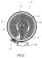
- Figures 1 and 3 show an embodiment of the hob 10 with a base shell 12 and a base shell 12 bridging hotplate 14.
- the base shell 12 has disc-like base part 16 and a ring part 18, the on the upper side 20 of the disk-shaped base part 16 is attached.
- On the top 20 of the base part 16 or the base shell 12 is a resistance heating element 22 established that forms a heat radiation source.
- the hotplate 14 consists of sintered silicon carbite, in particular from liquid phase sintered silicon carbide.
- a arranged rod-shaped temperature sensor element 26 In from the base shell 12 and the hotplate 14 sintered silicon carbide defined space 24 is a arranged rod-shaped temperature sensor element 26, the takes advantage of the thermal expansion principle.
- the Temperature sensor element 26 is with a switching device 28 combined on the outside of the base shell 12 under the edge region protruding beyond the base shell 12 30 of the hotplate 14 is mounted.
- Another option is at the bottom 40 of the hotplate made of sintered silicon carbide at least to provide a temperature sensor, for example in Thick film technology can be realized.
- This at least one temperature sensor can by means of a Shielding against the radiation of the Resistance heating element 22 to be shielded.
- the hob 10 with a Combination of a rod-shaped temperature sensor element 26 and at least one temperature sensor of the above Way of training.
- reference numeral 42 is one Designated connection device, by means of which the Resistance heating element 22 to a suitable energy source can be connected.
Landscapes
- Chemical & Material Sciences (AREA)
- Engineering & Computer Science (AREA)
- Ceramic Engineering (AREA)
- Resistance Heating (AREA)
- Magnetic Heads (AREA)
Applications Claiming Priority (2)
| Application Number | Priority Date | Filing Date | Title |
|---|---|---|---|
| DE29617732U | 1996-10-12 | ||
| DE29617732U DE29617732U1 (de) | 1996-10-12 | 1996-10-12 | Kochmulde |
Publications (1)
| Publication Number | Publication Date |
|---|---|
| EP0836056A1 true EP0836056A1 (fr) | 1998-04-15 |
Family
ID=8030475
Family Applications (1)
| Application Number | Title | Priority Date | Filing Date |
|---|---|---|---|
| EP97117218A Withdrawn EP0836056A1 (fr) | 1996-10-12 | 1997-10-04 | Plaque de cuisson |
Country Status (2)
| Country | Link |
|---|---|
| EP (1) | EP0836056A1 (fr) |
| DE (1) | DE29617732U1 (fr) |
Families Citing this family (3)
| Publication number | Priority date | Publication date | Assignee | Title |
|---|---|---|---|---|
| GB2335834B (en) * | 1998-03-26 | 2002-10-23 | Ceramaspeed Ltd | Radiant electric heater |
| DE19925228B4 (de) * | 1999-06-01 | 2007-11-15 | BSH Bosch und Siemens Hausgeräte GmbH | Gargerät mit Restwärmeanzeige und Verfahren zum Betrieb der Restwärmeanzeige |
| DE10008646A1 (de) | 2000-02-24 | 2001-09-13 | Kempten Elektroschmelz Gmbh | Beschichteter Formkörper aus Siliciumnitrid |
Citations (3)
| Publication number | Priority date | Publication date | Assignee | Title |
|---|---|---|---|---|
| DE3526783A1 (de) * | 1985-07-26 | 1987-01-29 | Ego Elektro Blanc & Fischer | Strahlungs-heizeinheit |
| US5233166A (en) * | 1991-07-31 | 1993-08-03 | Kyocera Corporation | Ceramic heater |
| DE4440005A1 (de) * | 1993-11-12 | 1995-05-18 | Kyocera Corp | Siliziumnitridkeramikheizer bzw. -erhitzer |
-
1996
- 1996-10-12 DE DE29617732U patent/DE29617732U1/de not_active Expired - Lifetime
-
1997
- 1997-10-04 EP EP97117218A patent/EP0836056A1/fr not_active Withdrawn
Patent Citations (3)
| Publication number | Priority date | Publication date | Assignee | Title |
|---|---|---|---|---|
| DE3526783A1 (de) * | 1985-07-26 | 1987-01-29 | Ego Elektro Blanc & Fischer | Strahlungs-heizeinheit |
| US5233166A (en) * | 1991-07-31 | 1993-08-03 | Kyocera Corporation | Ceramic heater |
| DE4440005A1 (de) * | 1993-11-12 | 1995-05-18 | Kyocera Corp | Siliziumnitridkeramikheizer bzw. -erhitzer |
Also Published As
| Publication number | Publication date |
|---|---|
| DE29617732U1 (de) | 1998-02-05 |
Similar Documents
| Publication | Publication Date | Title |
|---|---|---|
| DE4022846C2 (de) | Vorrichtung zur Leistungssteuerung und -begrenzung bei einer Heizfläche aus Glaskeramik oder einem vergleichbaren Material | |
| EP0229928B1 (fr) | Elément de chauffage pour appareils de chauffage notamment pour cuisinières | |
| EP0853444B1 (fr) | Système à cuire avec une plaque de cuisson électrique, transférant la chaleur par conduction | |
| DE69619521T2 (de) | Elektrische heizelemente | |
| DE69313731T2 (de) | Kochgefäss, insbesondere ein Kessel, mit einer integrierten Heizplatte | |
| AT398874B (de) | Elektrische strahlungsheizeinrichtung für kochgeräte mit ebener kochfläche | |
| DE69834791T2 (de) | Heizelement | |
| DE69830980T2 (de) | Zirkuläres Schichtsheizelement und Kochherd aus Porzellan-Email | |
| EP0250880B1 (fr) | Corps de chauffage à rayonnement | |
| DE2653389C2 (de) | Kochmulde | |
| DE2135449A1 (de) | Glasplatten Oberflachenheizeinheit mit gleichmaßiger Temperaturverteilung | |
| DE3728466A1 (de) | Kochgeraet | |
| EP0993233B1 (fr) | Inducteur destiné aux plaques à induction | |
| EP1258171A1 (fr) | Espace de cuisson a sonde pyrometrique | |
| AT389612B (de) | Elektrische strahlungsheizeinheit | |
| DE8133341U1 (de) | Elektrischer strahlungsheizer fuer herde mit glaskeramikdeckplatten | |
| DE69505471T2 (de) | Extraflaches Kochfeld für Einbau | |
| EP0757210A1 (fr) | Unité d'une table de suisson à rayonnement | |
| WO2011086504A2 (fr) | Dispositif d'appareil ménager | |
| DE19701640A1 (de) | Kontaktwärmeübertragendes Kochsystem mit einer Elektro-Kochplatte | |
| DE60201683T2 (de) | Kochgerät | |
| DE2301928A1 (de) | Elektrische waerme-, heiz- und/oder kocheinrichtung | |
| EP0866641A2 (fr) | Plaque de cuisson électrique | |
| DE19500448A1 (de) | Heizeinheit | |
| DE10110789C1 (de) | Kochgerät mit einer nicht planaren, mehrdimensional geformten Kochfläche aus Glas- oder Glaskeramik |
Legal Events
| Date | Code | Title | Description |
|---|---|---|---|
| PUAI | Public reference made under article 153(3) epc to a published international application that has entered the european phase |
Free format text: ORIGINAL CODE: 0009012 |
|
| AK | Designated contracting states |
Kind code of ref document: A1 Designated state(s): CH DE ES FR GB LI |
|
| AX | Request for extension of the european patent |
Free format text: AL;LT;LV;RO;SI |
|
| 17P | Request for examination filed |
Effective date: 19980415 |
|
| AKX | Designation fees paid |
Free format text: CH DE ES FR GB LI |
|
| RBV | Designated contracting states (corrected) |
Designated state(s): CH DE ES FR GB LI |
|
| RAP1 | Party data changed (applicant data changed or rights of an application transferred) |
Owner name: DIEHL AKO STIFTUNG & CO. KG |
|
| 17Q | First examination report despatched |
Effective date: 20000927 |
|
| STAA | Information on the status of an ep patent application or granted ep patent |
Free format text: STATUS: THE APPLICATION IS DEEMED TO BE WITHDRAWN |
|
| 18D | Application deemed to be withdrawn |
Effective date: 20020109 |