EP0837007A2 - Elément de récipient avec moyens de manipulation - Google Patents
Elément de récipient avec moyens de manipulation Download PDFInfo
- Publication number
- EP0837007A2 EP0837007A2 EP97117012A EP97117012A EP0837007A2 EP 0837007 A2 EP0837007 A2 EP 0837007A2 EP 97117012 A EP97117012 A EP 97117012A EP 97117012 A EP97117012 A EP 97117012A EP 0837007 A2 EP0837007 A2 EP 0837007A2
- Authority
- EP
- European Patent Office
- Prior art keywords
- container
- recess
- functional
- handle
- element according
- Prior art date
- Legal status (The legal status is an assumption and is not a legal conclusion. Google has not performed a legal analysis and makes no representation as to the accuracy of the status listed.)
- Withdrawn
Links
- 239000002184 metal Substances 0.000 claims description 16
- 125000002066 L-histidyl group Chemical group [H]N1C([H])=NC(C([H])([H])[C@](C(=O)[*])([H])N([H])[H])=C1[H] 0.000 claims 1
- 238000010137 moulding (plastic) Methods 0.000 claims 1
- 239000006261 foam material Substances 0.000 abstract 1
- 238000004519 manufacturing process Methods 0.000 description 5
- 230000015572 biosynthetic process Effects 0.000 description 2
- 238000005755 formation reaction Methods 0.000 description 2
- 238000000034 method Methods 0.000 description 2
- 230000003068 static effect Effects 0.000 description 2
- 101100390736 Danio rerio fign gene Proteins 0.000 description 1
- 101100390738 Mus musculus Fign gene Proteins 0.000 description 1
- 208000027418 Wounds and injury Diseases 0.000 description 1
- 238000004040 coloring Methods 0.000 description 1
- 230000006378 damage Effects 0.000 description 1
- 230000000694 effects Effects 0.000 description 1
- 230000001771 impaired effect Effects 0.000 description 1
- 238000002347 injection Methods 0.000 description 1
- 239000007924 injection Substances 0.000 description 1
- 238000001746 injection moulding Methods 0.000 description 1
- 208000014674 injury Diseases 0.000 description 1
- 238000003780 insertion Methods 0.000 description 1
- 230000037431 insertion Effects 0.000 description 1
- 238000009420 retrofitting Methods 0.000 description 1
- 239000000243 solution Substances 0.000 description 1
- 238000003860 storage Methods 0.000 description 1
- 230000007704 transition Effects 0.000 description 1
Images




Classifications
-
- B—PERFORMING OPERATIONS; TRANSPORTING
- B65—CONVEYING; PACKING; STORING; HANDLING THIN OR FILAMENTARY MATERIAL
- B65D—CONTAINERS FOR STORAGE OR TRANSPORT OF ARTICLES OR MATERIALS, e.g. BAGS, BARRELS, BOTTLES, BOXES, CANS, CARTONS, CRATES, DRUMS, JARS, TANKS, HOPPERS, FORWARDING CONTAINERS; ACCESSORIES, CLOSURES, OR FITTINGS THEREFOR; PACKAGING ELEMENTS; PACKAGES
- B65D45/00—Clamping or other pressure-applying devices for securing or retaining closure members
- B65D45/02—Clamping or other pressure-applying devices for securing or retaining closure members for applying axial pressure to engage closure with sealing surface
- B65D45/16—Clips, hooks, or clamps which are removable, or which remain connected either with the closure or with the container when the container is open, e.g. C-shaped
- B65D45/20—Clips, hooks, or clamps which are removable, or which remain connected either with the closure or with the container when the container is open, e.g. C-shaped pivoted
- B65D45/24—Clips, hooks, or clamps which are removable, or which remain connected either with the closure or with the container when the container is open, e.g. C-shaped pivoted incorporating pressure-applying means, e.g. screws or toggles
-
- B—PERFORMING OPERATIONS; TRANSPORTING
- B65—CONVEYING; PACKING; STORING; HANDLING THIN OR FILAMENTARY MATERIAL
- B65D—CONTAINERS FOR STORAGE OR TRANSPORT OF ARTICLES OR MATERIALS, e.g. BAGS, BARRELS, BOTTLES, BOXES, CANS, CARTONS, CRATES, DRUMS, JARS, TANKS, HOPPERS, FORWARDING CONTAINERS; ACCESSORIES, CLOSURES, OR FITTINGS THEREFOR; PACKAGING ELEMENTS; PACKAGES
- B65D45/00—Clamping or other pressure-applying devices for securing or retaining closure members
- B65D45/02—Clamping or other pressure-applying devices for securing or retaining closure members for applying axial pressure to engage closure with sealing surface
- B65D45/16—Clips, hooks, or clamps which are removable, or which remain connected either with the closure or with the container when the container is open, e.g. C-shaped
- B65D45/20—Clips, hooks, or clamps which are removable, or which remain connected either with the closure or with the container when the container is open, e.g. C-shaped pivoted
- B65D45/22—Clips, hooks, or clamps which are removable, or which remain connected either with the closure or with the container when the container is open, e.g. C-shaped pivoted resilient
Definitions
- the invention relates to a container element with a functional part for handling, in particular locking or transporting the same.
- Such a container element is known from DE 295 13 986 U1; the present invention also relates in particular to insulating containers, for storing and transporting food are used, with a closed thermal envelope of Meaning is.
- the generic utility model Disadvantages of injury to the envelope by retrofitting Handles avoided by using a special manufacturing process the rod-shaped provided there as a handle Functional parts first inserted into the still elastic cover and then the container is foamed from the inside as usual becomes. But this also means that these functional parts then for are always in place or in other words that already in the manufacture of the container it must be determined which type of functional parts on the container should be arranged accordingly the function of this container.
- this object is according to the characterizing part of claim 1 solved.
- connection between the functional part and the Container on a holding part, which has positive locking elements on the container, Can be snapped or snapped onto its lid or in the bottom is held so that the same for the respective functional part static and dynamic functional requirements, for example a fixed swivel axis, as with one of static fixation in the container itself, just like at the stand of the technique.
- the holding part can be used depending on the demands Be plastic part, but also as a metal profile in particular round cross section, as this is high mechanical Stability can be combined with simple manufacture, and also on simple type of swivel and rotary axes for the respective functional parts can be defined.
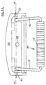
- FIG. 1 shows a first exemplary embodiment of a container element, which has a holding part for fastening in the lid of the container, that in the illustrated embodiment from a U-shaped design Metal profile 10 with a round cross section.
- a first section 10A is in contact with the wall of the cover, the ends of the two legs of the U-shaped metal profile 10 are so directed against each other that they are in an axis X-X with each other align the pivot axis for the here as a locking bracket 20th form trained functional part.
- This pivot axis X-X lies parallel and about the same height as the rear, raised Part of the U-bracket 10.
- the locking bracket 20 is through a essentially H-shaped plastic part formed, the upper H-leg the second section 10B, the ends of the metal profile 10 by elastic overlap by means of a slot 20S (Detailed view of Figure 1), encloses so that the locking bracket 20 is pivotally mounted about this axis.
- the lower two H-legs are turned inwards so that they engage here with correspondingly shaped wall areas of the Receiving part of the container can come.
- Figure 2 shows this container element in the installed state in one container formed from receiving part 30 and cover 40, here the closed position is shown, that is, the position where the lower H ends 20A, 20B corresponding formations in the receiving part 30 overlap and thus snap in there.
- the metal profile 10 is in the functional position of the locking bracket shown in Figure 2 20 in or between the wall areas A, B, C of a recess 41 held in the cover 40 so that the entire container element as a closure between the receiving part 30 and cover 40 in the occurring in the usual way when opening and closing the closure Under no circumstances should force be exerted from recess 41 can be pulled out.
- the Locking bracket 20 sufficient self-elasticity that by corresponding force exerted by the closure from that shown in FIG shown locking position forward with its two lower H sections 20A, 20B are disengaged from the receiving part 30 can and then at least as far in the direction of the two double arrows can be pivoted that the cover 40 from the receiving part 30th can be removed.
- Figure 3 shows a schematic representation of the Handling the lock
- position 3 is the Closure in the closure position shown in Figure 2, in which Lid 40 and receiving part 30 are held firmly on top of each other Figure 3B is the latch released and in Figure 3C the latch is 20 pivoted inwards into the recess 41 so that it there in a kind of storage position in the lid, where he the Handling of the lid is not hindered.
- Figure 4 shows a perspective view similar to Figure 1 shows a modified, second embodiment of a Closure element, which in principle is carried out in the same way but as Toggle lock is designed.
- the metal profile 10 is formed here in two parts, the first, U-shaped Section 10A in turn serves to hold the Closure in the recess 41 of the lid 40, where it between the Side walls of the recess 41 and locking knobs 43 in the functional position the closure is also held securely.
- the second subsection exists 10B of the metal profile also from a flat U-shaped Part that in the ends of the first section 10A is pivotally held and that at its base part by the locking bracket 20 is overlapped, so that in addition to the pivot axis X-X defines a further pivot axis Y-Y running parallel to this becomes.
- FIG. 4 shows this toggle lock during assembly or disassembly in the recess 41; one can see that the entire toggle lock is like a drawer in Inserted in the direction of the double arrow in the lid 40 and there locked (assembly) or by appropriate force from the Latches 43 are also pulled out again (disassembly) can.
- This feature is all embodiments of the container elements common according to the invention and represents an essential property of this technique.
- Figure 5 shows the three sectional views How the toggle lock works:
- Figure 5A shows the closure in its functional position, ie in the stop position, at the cover 40 and receiving part 30 of the Container are pressed together.
- the actuator 21 is oriented so that its lower, shorter U-leg on the Bottom of the recess 41 rests and the two pivot axes X-X and Y-Y in the direction normal to the bottom of the recess 41 lie one above the other, i.e. in a position in which the locking bracket 20 or its lower H-leg 20A, 20B the two container parts 30.40 pulls the most against each other (closed position).
- Figure 5B shows the release of the closure in the upper Operating surface of the operating part 21 is pulled (direction of Arrow PF); this gives the lower, shorter U-leg of the Actuating part 21, the two legs 10C of the second section 10B of the metal bracket 10 free, so that the upper pivot axis X-X, on which the locking bracket 20 is articulated, to the outside can pivot away, causing the upper pivot axis X-X to move moved below and thereby the closure member 20 the corresponding Formation in the receiving part 30 of the container releases and to the outside can be pivoted away.
- Figures 6A and B show schematic principle representations of a third embodiment of the container element according to the invention, here the container element forms a transport device.
- the container element forms a transport device.
- a metal bracket 10 in latches 42 in a recess 31 of the receiving part 30 of the container locked.
- the first variant (FIG. 6A) of this container element the entire transport device, by inserting the The bracket 10 is simply mounted in or through these locking elements Pulling out can be dismantled.
- FIG. 6B Simplified variant can be provided (Fig. 6B), in which the Metal profile 10 and the handle 50 as a one-piece component or rigidly connected components are formed, which the in Figure 6A shown functional position after latching permanently.
- FIG. 7A to 7D show the structure and structure in different representations Assembly of a holding part designed as a handle holding plate 60 for a handle 50.
- the individual elements according to FIG. 7B only by jamming and Interlocking can be assembled like a kit
- Fig. 7C shows one partially sectioned view of a recess 31 in the container 30 used handle plate 60
- the Figs. 7D show the Securing the handle plate 60, as shown in Fig. 7C Functional position using specially designed components.
- the central component of this component system is a one-piece, for example as an injection molded part, handle holding plate 60, the aligned on both sides with the intended swivel axis X-X one Carrying handle 50 has cylindrical recesses 62A, 63A.
- the Handle 50 consists of two U-shaped side parts 55, 56 a round profile and a plastic support member 57, which also has cylindrical bores on the end face.
- cylindrical Plastic locking sleeves 62, 63 are provided which face the outside showing the remaining opening area of the cylindrical bores 62A, 63A, as shown in particular in the illustration of FIG 7C can be seen.
- the outer contour of these securing sleeves 62, 63 is adapted to the outer contour of the handle holding plate 60.
- the unit thus formed is in a recess 31 of the container 30 introduced like a drawer, so the undercut-like design of the profile of the recess 31 Clamping effect with respect to the locking sleeves 32, 33, so that these in the functional position of the functional unit in the recess 31 of the Container 30 are no longer removable and consequently also the handle 50 is secured without its pivotability around the Swivel axis X-X is impaired.
- the recess 31 also has an end wall, which acts as a stop for the handle holding plate 60 serves and in this position the functional position of the Pivot axis X-X and thus the handle 50 specifies.
- stamp-like locking element 61 also expediently a Plastic injection molding
- a stamp-like locking element 61 also expediently a Plastic injection molding
- FIGS. 7D The function of this locking is shown in FIGS. 7D in detail explained briefly, the cross sections in the plane A-B of the 7C and assigned to individual functional positions 1-3 are:
- the hole is in this area 61A expanded so that an annular groove 68A forms, into which one sleeve-like plastic cap 68 fits snugly.
- the handle holding plate 60 in the recess 31 achieves this Securing element 61 in this position in the recess 31 introduced recess 35 into which the securing element 31 can be inserted a few millimeters so that the handle holding plate 60 is no longer movable in this position.
- This position will secured by the fact that the sleeve-like cap 68 now on the outward end of the securing element 61 or in the Ring groove 68A is pressed in and jammed there. That is the assembly of the handle 50 in the container 30 ended.
- Figure 8 finally shows a fourth embodiment, here is in a recess in the bottom 35 of the receiving part 30 of the Container held a bracket 61 so that its free end as an axis a wheel 60 is used, so that here in an equally simple manner a container can be equipped for transport.
Landscapes
- Engineering & Computer Science (AREA)
- Mechanical Engineering (AREA)
- Details Of Rigid Or Semi-Rigid Containers (AREA)
Applications Claiming Priority (2)
| Application Number | Priority Date | Filing Date | Title |
|---|---|---|---|
| DE19641123 | 1996-10-05 | ||
| DE1996141123 DE19641123A1 (de) | 1996-10-05 | 1996-10-05 | Behälterelement mit einem Funktionsteil zur Handhabung, insbesondere Verschluß oder Transport desselben |
Publications (2)
| Publication Number | Publication Date |
|---|---|
| EP0837007A2 true EP0837007A2 (fr) | 1998-04-22 |
| EP0837007A3 EP0837007A3 (fr) | 1999-08-18 |
Family
ID=7807958
Family Applications (1)
| Application Number | Title | Priority Date | Filing Date |
|---|---|---|---|
| EP97117012A Withdrawn EP0837007A3 (fr) | 1996-10-05 | 1997-10-01 | Elément de récipient avec moyens de manipulation |
Country Status (2)
| Country | Link |
|---|---|
| EP (1) | EP0837007A3 (fr) |
| DE (1) | DE19641123A1 (fr) |
Cited By (1)
| Publication number | Priority date | Publication date | Assignee | Title |
|---|---|---|---|---|
| CN103057821A (zh) * | 2011-10-24 | 2013-04-24 | 宝培拉机箱系统有限公司 | 具有下部和盖的壳体 |
Citations (1)
| Publication number | Priority date | Publication date | Assignee | Title |
|---|---|---|---|---|
| DE29513986U1 (de) | 1995-05-24 | 1995-11-09 | Etol Vertriebs GmbH, 77728 Oppenau | Behälter |
Family Cites Families (10)
| Publication number | Priority date | Publication date | Assignee | Title |
|---|---|---|---|---|
| DE1728328U (de) * | 1956-03-26 | 1956-08-16 | Walter Heubl | Selbstaendiger flaschenschnellverschluss. |
| CH547208A (de) * | 1971-12-23 | 1974-03-29 | Oerlikon Buehrle Ag | Im spritzgussverfahren hergestellter transportbehaelter mit traggriffen. |
| DE2434283A1 (de) * | 1974-07-17 | 1976-01-29 | Sotralentz Sa | Kunststoffbehaelter, insbesondere fass |
| EP0175022A1 (fr) * | 1984-09-06 | 1986-03-26 | SAMSONITE CORPORATION (a Delaware corporation) | Poignée pour guider une valise |
| FR2647759A1 (fr) * | 1989-05-31 | 1990-12-07 | Lhotellier Montrichard Sa | Perfectionnements apportes aux conteneurs |
| DE3934663C2 (de) * | 1989-10-18 | 1994-11-10 | Mann & Hummel Filter | Spannverschluß |
| DE9214938U1 (de) * | 1992-11-03 | 1993-03-18 | Filterwerk Mann & Hummel Gmbh, 7140 Ludwigsburg | Kniehebelverschluß für Ansaugluftfilter von Brennkraftmaschinen, Kompressoren und sonstigen luftansaugenden Maschinen |
| US5518139A (en) * | 1993-11-24 | 1996-05-21 | Waterloo Industries, Inc. | Portable storage assembly |
| US5373708A (en) * | 1994-01-25 | 1994-12-20 | Dumoulin, Jr.; Joseph C. | Cooler with fold-down corner wheels, a pop-up pull handle, integral bottle and fold down cutting board |
| DE4426548A1 (de) * | 1994-07-27 | 1996-02-01 | Gelszat Werner | Fahrbarer Getränkekasten mit klappbaren Rädern |
-
1996
- 1996-10-05 DE DE1996141123 patent/DE19641123A1/de not_active Ceased
-
1997
- 1997-10-01 EP EP97117012A patent/EP0837007A3/fr not_active Withdrawn
Patent Citations (1)
| Publication number | Priority date | Publication date | Assignee | Title |
|---|---|---|---|---|
| DE29513986U1 (de) | 1995-05-24 | 1995-11-09 | Etol Vertriebs GmbH, 77728 Oppenau | Behälter |
Cited By (1)
| Publication number | Priority date | Publication date | Assignee | Title |
|---|---|---|---|---|
| CN103057821A (zh) * | 2011-10-24 | 2013-04-24 | 宝培拉机箱系统有限公司 | 具有下部和盖的壳体 |
Also Published As
| Publication number | Publication date |
|---|---|
| DE19641123A1 (de) | 1998-04-16 |
| EP0837007A3 (fr) | 1999-08-18 |
Similar Documents
| Publication | Publication Date | Title |
|---|---|---|
| EP1709269A1 (fr) | Dispositif de clipsage a l'aide de dispositifs ressorts a lames destines au montage rapide de ferrures comme des serrures a levier pivotant, des parties charnieres dans des ouvertures d'une paroi mince | |
| DE19728641A1 (de) | Positionsscharnier für Türen | |
| EP0422678B1 (fr) | Coffre à bagages | |
| EP1709267A1 (fr) | Fixation par clipsage pour le montage rapide de dispositifs d'armature, des fermetures a levier pivotant ou des pieces de charniere par exemple, dans des ouvertures menagees dans une paroi mince | |
| EP1857616A2 (fr) | Fermeture à fixer dans des ouvertures menagées dans une paroi mince | |
| DE3328242C2 (fr) | ||
| EP0566983A1 (fr) | Valise | |
| DE3305272A1 (de) | Befestigungsplatte fuer scharnierarm | |
| EP0647756A1 (fr) | Charnière pour portes, fenêtres ou similaires | |
| EP0585952A2 (fr) | Fermeture de serrage à verrou pour ridelles rabattables de camions | |
| EP0490023A1 (fr) | Dispositif de bouton-poussoirs | |
| DE3230312C2 (fr) | ||
| EP0837007A2 (fr) | Elément de récipient avec moyens de manipulation | |
| DE2144756C3 (de) | Fernbetätigungsvorrichtung, insbesondere für Kraftfahrzeugtürschlösser | |
| DE2703207B2 (de) | Lüftungsvorrichtung für Räume | |
| DE9114374U1 (de) | Treibstangenbeschlag für Fenster, Türen o.dgl. | |
| EP0348790B1 (fr) | Tiroir ou similaire avec au moins une cloison réglable | |
| DE60112364T2 (de) | In zwei zueinander orthogonalen richtungen drehbarer rahmen, insbesondere des fensterrahmentypes | |
| DE1079369B (de) | Dehnbares Gliederband | |
| EP1900892A1 (fr) | Verrou à barre rotative | |
| DE604569C (de) | Kombinationsschloss mit quer verschiebbaren Sperriegeln | |
| EP1428633A1 (fr) | Boíte | |
| EP0154671A2 (fr) | Ventilation par registre | |
| DE2152199A1 (de) | Tuerschloss mit einem verriegelungsund klinkenmechanismus | |
| DE2329291C3 (de) | Verschluß für Koffer o.dgl |
Legal Events
| Date | Code | Title | Description |
|---|---|---|---|
| PUAI | Public reference made under article 153(3) epc to a published international application that has entered the european phase |
Free format text: ORIGINAL CODE: 0009012 |
|
| AK | Designated contracting states |
Kind code of ref document: A2 Designated state(s): AT CH DE FR GB IT LI NL |
|
| RHK1 | Main classification (correction) |
Ipc: B65D 25/28 |
|
| RIC1 | Information provided on ipc code assigned before grant |
Free format text: 6B 65D 25/28 A, 6B 65D 25/24 B, 6B 65D 45/22 B, 6B 65D 45/24 B, 6B 65D 25/20 B |
|
| PUAL | Search report despatched |
Free format text: ORIGINAL CODE: 0009013 |
|
| AK | Designated contracting states |
Kind code of ref document: A3 Designated state(s): AT BE CH DE DK ES FI FR GB GR IE IT LI LU MC NL PT SE |
|
| RAP1 | Party data changed (applicant data changed or rights of an application transferred) |
Owner name: WOLF KUNSTSTOFFE GMBH |
|
| RIN1 | Information on inventor provided before grant (corrected) |
Inventor name: WOLF KUNSTSTOFFE GMBH |
|
| 17P | Request for examination filed |
Effective date: 20000113 |
|
| AKX | Designation fees paid |
Free format text: AT BE CH DE DK ES FI LI |
|
| RBV | Designated contracting states (corrected) |
Designated state(s): AT CH DE FR GB IT LI NL |
|
| 17Q | First examination report despatched |
Effective date: 20010802 |
|
| STAA | Information on the status of an ep patent application or granted ep patent |
Free format text: STATUS: THE APPLICATION HAS BEEN WITHDRAWN |
|
| 18W | Application withdrawn |
Withdrawal date: 20011117 |