EP0838268A1 - Vorrichtung zum auftragen von klebstoff - Google Patents
Vorrichtung zum auftragen von klebstoff Download PDFInfo
- Publication number
- EP0838268A1 EP0838268A1 EP97918405A EP97918405A EP0838268A1 EP 0838268 A1 EP0838268 A1 EP 0838268A1 EP 97918405 A EP97918405 A EP 97918405A EP 97918405 A EP97918405 A EP 97918405A EP 0838268 A1 EP0838268 A1 EP 0838268A1
- Authority
- EP
- European Patent Office
- Prior art keywords
- adhesive applying
- purging
- circuit board
- nozzle
- cam
- Prior art date
- Legal status (The legal status is an assumption and is not a legal conclusion. Google has not performed a legal analysis and makes no representation as to the accuracy of the status listed.)
- Granted
Links
Images





Classifications
-
- B—PERFORMING OPERATIONS; TRANSPORTING
- B05—SPRAYING OR ATOMISING IN GENERAL; APPLYING FLUENT MATERIALS TO SURFACES, IN GENERAL
- B05C—APPARATUS FOR APPLYING FLUENT MATERIALS TO SURFACES, IN GENERAL
- B05C11/00—Component parts, details or accessories not specifically provided for in groups B05C1/00 - B05C9/00
- B05C11/10—Storage, supply or control of liquid or other fluent material; Recovery of excess liquid or other fluent material
- B05C11/1002—Means for controlling supply, i.e. flow or pressure, of liquid or other fluent material to the applying apparatus, e.g. valves
- B05C11/1034—Means for controlling supply, i.e. flow or pressure, of liquid or other fluent material to the applying apparatus, e.g. valves specially designed for conducting intermittent application of small quantities, e.g. drops, of coating material
-
- B—PERFORMING OPERATIONS; TRANSPORTING
- B05—SPRAYING OR ATOMISING IN GENERAL; APPLYING FLUENT MATERIALS TO SURFACES, IN GENERAL
- B05B—SPRAYING APPARATUS; ATOMISING APPARATUS; NOZZLES
- B05B15/00—Details of spraying plant or spraying apparatus not otherwise provided for; Accessories
- B05B15/50—Arrangements for cleaning; Arrangements for preventing deposits, drying-out or blockage; Arrangements for detecting improper discharge caused by the presence of foreign matter
- B05B15/52—Arrangements for cleaning; Arrangements for preventing deposits, drying-out or blockage; Arrangements for detecting improper discharge caused by the presence of foreign matter for removal of clogging particles
-
- B—PERFORMING OPERATIONS; TRANSPORTING
- B05—SPRAYING OR ATOMISING IN GENERAL; APPLYING FLUENT MATERIALS TO SURFACES, IN GENERAL
- B05C—APPARATUS FOR APPLYING FLUENT MATERIALS TO SURFACES, IN GENERAL
- B05C5/00—Apparatus in which liquid or other fluent material is projected, poured or allowed to flow on to the surface of the work
- B05C5/02—Apparatus in which liquid or other fluent material is projected, poured or allowed to flow on to the surface of the work the liquid or other fluent material being discharged through an outlet orifice by pressure, e.g. from an outlet device in contact or almost in contact, with the work
- B05C5/0208—Apparatus in which liquid or other fluent material is projected, poured or allowed to flow on to the surface of the work the liquid or other fluent material being discharged through an outlet orifice by pressure, e.g. from an outlet device in contact or almost in contact, with the work for applying liquid or other fluent material to separate articles
-
- H—ELECTRICITY
- H05—ELECTRIC TECHNIQUES NOT OTHERWISE PROVIDED FOR
- H05K—PRINTED CIRCUITS; CASINGS OR CONSTRUCTIONAL DETAILS OF ELECTRIC APPARATUS; MANUFACTURE OF ASSEMBLAGES OF ELECTRICAL COMPONENTS
- H05K13/00—Apparatus or processes specially adapted for manufacturing or adjusting assemblages of electric components
- H05K13/04—Mounting of components, e.g. of leadless components
- H05K13/046—Surface mounting
- H05K13/0469—Surface mounting by applying a glue or viscous material
-
- Y—GENERAL TAGGING OF NEW TECHNOLOGICAL DEVELOPMENTS; GENERAL TAGGING OF CROSS-SECTIONAL TECHNOLOGIES SPANNING OVER SEVERAL SECTIONS OF THE IPC; TECHNICAL SUBJECTS COVERED BY FORMER USPC CROSS-REFERENCE ART COLLECTIONS [XRACs] AND DIGESTS
- Y10—TECHNICAL SUBJECTS COVERED BY FORMER USPC
- Y10T—TECHNICAL SUBJECTS COVERED BY FORMER US CLASSIFICATION
- Y10T156/00—Adhesive bonding and miscellaneous chemical manufacture
- Y10T156/17—Surface bonding means and/or assemblymeans with work feeding or handling means
- Y10T156/1798—Surface bonding means and/or assemblymeans with work feeding or handling means with liquid adhesive or adhesive activator applying means
Definitions
- the present invention relates to an adhesive applying apparatus for applying an adhesive for fixing an electronic component onto a circuit board.
- a reference character A denotes a perspective view of a prior art adhesive applying apparatus.
- the reference character B denotes an applying mechanism provided with an applying nozzle 1 for applying an adhesive 3, a syringe 2 for supplying the adhesive 3 to the applying nozzle 1 and a monitor camera 13.
- the reference character C denotes a purging (discard) station mechanism provided with a purging tape 5 for purging the adhesive 3 and a purging station 6 which is located beside a circuit board conveyance unit 10 and places thereon the purging tape 5 in a purging stage.
- the aforementioned circuit board conveyance unit 10 and the purging station 6 are supported on an X-Y table 30 and is constructed so as to be able to position the applying nozzle 1 in an X-Y direction.
- Adhesive applying operation of the purging station to be executed by the prior art adhesive applying apparatus A prior to shipment from the factory will be described next with reference to Fig. 6 and Fig. 7.
- an operator when shipping an applying apparatus, an operator performs an adjustment for making the height of the upper surface of the purging tape 5 coincide with the height of the upper surface of a circuit board 4 conveyed by the circuit board conveyance unit 10 prior to shipment from the factory.
- This adjustment is performed by positioning the applying nozzle 1 above the purging station 6, moving down the nozzle to a preset height corresponding to the upper surface of the aforementioned circuit board 4, loosening screws by which the purging station 6 is mounted so that the tip of the applying nozzle 1 is put right in contact with the upper surface of the purging tape 5 on the purging station 6 within a stroke in which the board 4 and the nozzle 1 is put in contact with each other as shown in Fig. 7, thereby vertically adjusting the position of the purging station 6.
- the height position adjustment of the purging station 6 and the circuit board 4 has required much time. Furthermore, if the height of the upper surface of the purging tape 5 is not coinciding with the height of the upper surface of the circuit board 4 conveyed by the circuit board conveyance unit 10, there occurs the issue that appropriate purging cannot be performed due to the phenomenon that the tip of the applying nozzle 1 is separated from the upper surface of the purging tape 5 or the phenomenon that the tip of the applying nozzle 1 collides against the purging station 6 via the purging tape 5.
- the present invention has an object to provide an adhesive applying apparatus capable of easily and speedily performing the adjustment of the vertical positional relationship between the upper surface of the circuit board and the upper surface of the purging station in the adjustment stage prior to shipment from the factory or in changing the type of the circuit board.
- the present invention is constructed as follows.
- an adhesive applying apparatus comprising:
- the lowermost end position of the applying nozzle can be appropriately set both in the position of the upper surface of the circuit board and in the position of the upper surface of the purging tape placed on the purging station. Therefore, appropriate adhesive applying can be performed even when the upper surface of the circuit board is not coinciding with the upper surface of the purging station.
- an adhesive applying apparatus based on the first aspect, wherein the elevation drive unit moves the adhesive applying nozzle down to the lowermost end position according to a thickness of the circuit board upon receiving a command for setting the lowermost end position of the adhesive applying nozzle to a height of the circuit board from the control means.
- an adhesive applying apparatus based on the first or second aspect, wherein the elevation drive unit is provided with a cam having a curved cam surface, a motor for rotating the cam, a cam follower which moves on the cam surface of the cam, and a shaft which is connected to the nozzle and moves up and down when the cam follower moves on the cam surface of the cam, the motor rotating according to the command from the control means, consequently rotating the cam, moving the cam follower on the cam surface of the cam, moving down the shaft and moving down the adhesive applying nozzle to the set lowermost end position.
- an adhesive applying apparatus based on the third aspect, wherein the cam has two cam surfaces of different curvatures so that the lowermost end position of the adhesive applying nozzle is varied when the cam follower is moved on the two cam surfaces by the rotation of the motor.
- an adhesive applying apparatus comprising:
- the height position of the purging station can be easily speedily adjusted when a displacement occurs between the position of the upper surface of the circuit board and the position of the upper surface of the purging tape placed on the purging station. Therefore, appropriate purging can be performed.
- an adhesive applying apparatus based on the fifth aspect, wherein the station elevation unit moves up and down the purging station according to a thickness of the circuit board upon receiving the command for setting the height of the purging station to the height of the circuit board from the control means.
- an adhesive applying apparatus based on any of the fourth through sixth aspects, wherein the station elevation unit is provided with a motor and a threaded shaft which is driven by the motor to move up and down the purging station.
- an adhesive applying apparatus based on any of the first through seventh aspects, wherein the circuit board is supported by being positioned by the support unit with its lower surface served as a reference, and the height of the upper surface of the circuit board is changed every time the thickness of the circuit board is varied.
- the reference character A denotes a perspective view of the adhesive applying apparatus of the first embodiment.
- the reference character B denotes an applying mechanism provided with a plurality of applying nozzles 1 for applying an adhesive 3, a plurality of syringes 2 for supplying the adhesive 3 to the plurality of applying nozzles 1, and a monitor camera 13.
- the reference character C denotes a purging (discard) station mechanism provided with a purging tape 5 which purges the adhesive 3 while being rewound from a reel 200 and wound around a reel 201, a purging station 6 which is located beside a circuit board conveyance unit 10 of an example of a circuit board support unit and on which the purging tape 5 is placed in a purging stage, a ball thread shaft 7 which rotates to vertically move the purging station 6 to thereby position the station in the vertical direction (Z direction), and a vertical movement motor 8 for rotating the ball thread shaft 7.
- a purging (discard) station mechanism provided with a purging tape 5 which purges the adhesive 3 while being rewound from a reel 200 and wound around a reel 201
- a purging station 6 which is located beside a circuit board conveyance unit 10 of an example of a circuit board support unit and on which the purging tape 5 is placed in a purging stage
- a ball thread shaft 7 which rotates to vertically move the purging station
- the aforementioned circuit board conveyance unit 10 and purging station 6 are supported on an X-Y table 30 of an example of a transverse drive unit for moving the applying nozzle 1 in a transverse direction, e.g., X-Y direction perpendicular to the vertical direction and are constructed so that they can be positioned in a horizontal direction (X-Y direction) relative to the applying nozzle 1.
- a transverse drive unit for moving the applying nozzle 1 in a transverse direction, e.g., X-Y direction perpendicular to the vertical direction and are constructed so that they can be positioned in a horizontal direction (X-Y direction) relative to the applying nozzle 1.
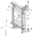
- Fig. 4 shows the construction of an elevation drive unit 100 for moving up and down the applying nozzle 1.
- the applying nozzle 1 and the syringe 2 are supported by a stroke shaft 14, the stroke shaft 14 is supported by a support fulcrum 15, and an arm 16 is pivotally supported by the support fulcrum 15.
- the arm 16 is pivotally supported at a fulcrum 20, and its end portion on the other side is urged by a spring 19.
- a cam follower 17 is provided halfway between the aforementioned support fulcrum 15 of the arm 16 and the aforementioned fulcrum 20, and a cam 18 is put in contact with the lower side of the cam follower 17.
- This cam 18 is driven by a motor 21 which rotates forwardly and reversely, and the motor 21 is controlled by a control section D.
- the top dead center position and the bottom dead center position of the adhesive applying nozzle 1 are determined by a position of the cam 18 indicated by ⁇ 1 and a position of the cam 18 indicated by ⁇ 2 . Then, by forwardly and reversely rotating the cam 18 within a range of ⁇ 1 to ⁇ 2 , the lowermost end position of the applying nozzle 1 is determined. By arbitrarily determining the ⁇ 1 and ⁇ 2 , the aforementioned lowermost end position can be adjusted.
- the control section D instructs the motor 21 about the aforementioned reciprocation pivot angle range of ⁇ 1 to ⁇ 2 .
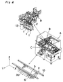
- Fig. 5 shows the details of the purging station mechanism C.
- the reference character D denotes a control section which controls the whole body of the adhesive applying apparatus A and includes an X-Y direction positioning mechanism for positioning an applying point of the circuit board 4 and positioning the purging station 6 in the X-Y direction by positioning the X-Y table 30, an applying control mechanism for moving and positioning the applying nozzle 1 of the applying mechanism B in the Z direction and a purging station control mechanism for moving and positioning the purging station 6 in the vertical direction by controlling the vertical movement motor 8.
- the reference character E denotes a display section which displays a control condition of the aforementioned applying control mechanism and a control condition of the aforementioned purging station control mechanism.
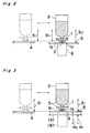
- the control section D sets the aforementioned ⁇ 1 and ⁇ 2 so that a vertical stroke S 1 of the applying nozzle 1 is adjusted to the lowermost end position coinciding with the position of the upper surface of the circuit board 4 conveyed by the circuit board conveyance unit 10.
- the purging can be performed without doing anything else.
- control section D changes the aforementioned stroke S 1 according to the height position of the purging tape 5 placed on the purging station 6 so as to make it a purging stroke S 2 , so that the tip of the positioning projection 1b of the applying nozzle 1 just coincides with the upper surface of a purging tape 5a.
- the applying nozzle 1 is moved down by the stroke S 2 , so that the tip of the positioning projection 1b of the applying nozzle 1 reaches the upper surface of the purging tape 5b, thereby performing the appropriate purging.
- the vertical stroke S 2 of the applying nozzle 1 set by the control section D is set back to the vertical stroke S 1 , and then adhesive applying on the circuit board 4 is performed.
- This arrangement obviates the need, as in the prior art, for the troublesome work of making the position of the upper surface of the purging tape 5 coincide with the position of the upper surface of the circuit board 4 by loosening the screws for fixing use and allows the work for changing the circuit board 4 for a new type to be easily and speedily performed.
- the vertical stroke S 1 of the applying nozzle 1 set by the control section D has a stroke length appropriate for the purging when the position of the upper surface of the circuit board 4 is coinciding with the position of the upper surface of the purging tape 5 placed on the purging station 6. Therefore, if the position of the upper surface of the purging tape 5 is lower than the position of the upper surface of the circuit board 4 as indicated by the dashed lines in Fig. 3, there is the issue that the tip of the positioning projection 1b of the applying nozzle 1 does not reach the upper surface of the purging tape 5 with the aforementioned vertical stroke S 1 kept intact, consequently causing abnormal applying position, size and shape of the adhesive discharged from the nozzle opening 1a.
- the vertical stroke S 1 of the applying nozzle 1 set by the control section D is kept intact, and a purging station control condition of the control section D is changed from a positioning condition H 1 in which the position of the upper surface of the purging tape 5 is lower than the position of the upper surface of the circuit board 4 into a positioning condition H 2 in which the position of the upper surface of the purging tape 5 coincides with the position of the upper surface of the circuit board 4, and the vertical movement motor 8 shown in Fig. 4 is rotated to rotate the ball thread shaft 7, thereby vertically moving the purging station 6 meshed with the ball thread shaft 7 and making the position of the upper surface of the purging tape 5 coincide with the position of the upper surface of the circuit board 4.
- the appropriate purging can be performed with the vertical stroke S 1 set by the control section D kept intact.
- an adhesive applying apparatus is provided with an operating knob 12 in place of the vertical movement motor 8 of the second embodiment, and it is also possible to rotate a ball thread shaft 11 by forwardly and reversely rotating the operating knob 12, thereby vertically moving the purging station 6 for the positioning of it in the vertical direction.
- the aforementioned embodiments can be applied to the following cases other than the case where height adjustment between the upper surface of a circuit board to be a reference and the upper surface of the purging tape 5 is performed prior to shipment from the factory. That is, in a case where the circuit board 4 is changed to one having a varied thickness according to the change of the type of the circuit board 4 and the circuit board 4 is supported by the circuit board conveyance unit 10 with the lower surface of the board 4 served as a reference, the height of the upper surface of the circuit board 4 differs from the height of the upper surface of the purging tape 5. In such a case, the adjustment of the lowermost end position of the aforementioned applying nozzle 1 or the adjustment of the position of the upper surface of the purging tape 5 of the purging station 6 according to the aforementioned embodiment can be performed.
- the aforementioned adhesive applying apparatus is constructed so that the elevation drive unit of the adhesive applying nozzle can arbitrarily set the lowermost end position of the adhesive applying nozzle and includes the control means for giving the aforementioned elevation drive unit a command for setting the lowermost end position of the adhesive applying nozzle located in a position above the purging station to a specified position.
- the appropriate purging can be performed by easily and speedily adjusting the lowermost end position of the applying nozzle so as to make it appropriate for the purging even when a displacement occurs in the height position between the upper surface of the circuit board and the upper surface of the purging station when the type of the circuit board is changed, so that an effect of improving the productivity can be obtained.
- the aforementioned adhesive applying apparatus has the station elevation unit for moving up and down the purging station and the control means for giving the aforementioned station elevation unit the command for setting the height of the purging station to the specified height.
Landscapes
- Engineering & Computer Science (AREA)
- Manufacturing & Machinery (AREA)
- Microelectronics & Electronic Packaging (AREA)
- Coating Apparatus (AREA)
- Electric Connection Of Electric Components To Printed Circuits (AREA)
Applications Claiming Priority (4)
| Application Number | Priority Date | Filing Date | Title |
|---|---|---|---|
| JP11738096 | 1996-05-13 | ||
| JP117380/96 | 1996-05-13 | ||
| JP11738096A JP3697315B2 (ja) | 1996-05-13 | 1996-05-13 | 接着剤塗布装置 |
| PCT/JP1997/001578 WO1997043050A1 (en) | 1996-05-13 | 1997-05-12 | Adhesive applying apparatus |
Publications (3)
| Publication Number | Publication Date |
|---|---|
| EP0838268A1 true EP0838268A1 (de) | 1998-04-29 |
| EP0838268A4 EP0838268A4 (de) | 2003-05-02 |
| EP0838268B1 EP0838268B1 (de) | 2005-03-16 |
Family
ID=14710226
Family Applications (1)
| Application Number | Title | Priority Date | Filing Date |
|---|---|---|---|
| EP97918405A Expired - Lifetime EP0838268B1 (de) | 1996-05-13 | 1997-05-12 | Vorrichtung zum auftragen von klebstoff |
Country Status (6)
| Country | Link |
|---|---|
| US (2) | US6050314A (de) |
| EP (1) | EP0838268B1 (de) |
| JP (1) | JP3697315B2 (de) |
| CN (1) | CN1074946C (de) |
| DE (1) | DE69732753T2 (de) |
| WO (1) | WO1997043050A1 (de) |
Cited By (2)
| Publication number | Priority date | Publication date | Assignee | Title |
|---|---|---|---|---|
| EP1160017A3 (de) * | 2000-06-01 | 2006-12-06 | Agilent Technologies, Inc. (a Delaware corporation) | Automatische, punktweise Ausgabestation und Verfahren |
| EP1897625A1 (de) * | 2006-09-07 | 2008-03-12 | Sika Technology AG | Vorrichtung zur Abgabe von viskosem oder pastösem Material |
Families Citing this family (17)
| Publication number | Priority date | Publication date | Assignee | Title |
|---|---|---|---|---|
| US6568447B1 (en) * | 1999-05-11 | 2003-05-27 | Kabushiki Kaisha Tiyoda Seisakusho | Cover glass adhering device |
| AU2000239097A1 (en) * | 2000-03-22 | 2001-10-03 | Applied Kinetic, Inc. | Manufacturing apparatus and method |
| US20050056215A1 (en) * | 2003-03-11 | 2005-03-17 | Shibaura Mechantronics Corporation | Apparatus for applying paste and method of applying paste |
| US20050001869A1 (en) * | 2003-05-23 | 2005-01-06 | Nordson Corporation | Viscous material noncontact jetting system |
| KR100540633B1 (ko) * | 2003-06-20 | 2006-01-11 | 주식회사 탑 엔지니어링 | 페이스트 도포기 및 그 제어 방법 |
| JP4815872B2 (ja) * | 2005-05-20 | 2011-11-16 | 株式会社日立プラントテクノロジー | ペースト塗布機 |
| JP4893016B2 (ja) * | 2006-02-17 | 2012-03-07 | 株式会社日立プラントテクノロジー | ペースト塗布機 |
| US9498790B2 (en) * | 2008-04-16 | 2016-11-22 | Imbox Shoecare A/S | Apparatus for impregnation of items with an impregnating agent |
| KR101000549B1 (ko) * | 2008-09-19 | 2010-12-14 | 주식회사 디엠에스 | 감광액 도포장치 |
| DE102012207206A1 (de) * | 2012-04-30 | 2013-10-31 | Winkler + Dünnebier Gmbh | Vorrichtung zum Auftragen von Klebemittel auf ein Material |
| CN102836801B (zh) * | 2012-08-06 | 2014-12-10 | 奇瑞汽车股份有限公司 | 一种汽车风挡玻璃涂胶装置及其涂胶方法 |
| JP6345071B2 (ja) * | 2014-10-06 | 2018-06-20 | 三菱重工機械システム株式会社 | 糊付装置及びこれを有する製函機 |
| DE102016000064A1 (de) | 2016-01-06 | 2017-07-06 | Baumer Hhs Gmbh | Klebstoffauftragsvorrichtung |
| JP6500244B2 (ja) * | 2016-06-09 | 2019-04-17 | パナソニックIpマネジメント株式会社 | 部品装着装置 |
| WO2018236397A1 (en) | 2017-06-23 | 2018-12-27 | Kimberly-Clark Worldwide, Inc. | ADHESIVE PATTERN RESIDING ON A MOBILE BASE STRIP |
| WO2018236395A1 (en) * | 2017-06-23 | 2018-12-27 | Kimberly-Clark Worldwide, Inc. | System and process for applying an adhesive to a moving web |
| CN115608555B (zh) * | 2022-11-12 | 2025-06-27 | 深圳市瑞荣自动化有限公司 | 一种MiniLED电路板涂布装置 |
Family Cites Families (18)
| Publication number | Priority date | Publication date | Assignee | Title |
|---|---|---|---|---|
| US2687111A (en) * | 1951-07-28 | 1954-08-24 | Ohio Commw Eng Co | Stamping unit for ink marking devices |
| GB1489071A (en) * | 1974-01-31 | 1977-10-19 | British United Shoe Machinery | Shoe upper conforming machines |
| GB2142257B (en) * | 1983-07-02 | 1986-11-26 | Gen Motors Overseas | Adhesive application apparatus |
| JPH0790193B2 (ja) * | 1986-01-13 | 1995-10-04 | 松下電器産業株式会社 | 接着剤塗布装置 |
| GB8613015D0 (en) * | 1986-05-29 | 1986-07-02 | Thomas T R | Porous ptfe |
| US4762578A (en) * | 1987-04-28 | 1988-08-09 | Universal Instruments Corporation | Non-contact sensing and controlling of spacing between a depositing tip and each selected depositing location on a substrate |
| US4829318A (en) * | 1987-09-30 | 1989-05-09 | Dataproducts, Inc. | Head tending system for purging and cleaning an ink jet print head |
| JPH0325916A (ja) * | 1989-06-22 | 1991-02-04 | Mitsubishi Electric Corp | 半導体装置の製造装置 |
| US5052338A (en) * | 1990-01-31 | 1991-10-01 | Asymptotic Technologies, Inc. | Apparatus for dispensing viscous materials a constant height above a workpiece surface |
| JP2836918B2 (ja) * | 1990-05-31 | 1998-12-14 | 松下電器産業株式会社 | 接着剤塗布装置 |
| US5320250A (en) * | 1991-12-02 | 1994-06-14 | Asymptotic Technologies, Inc. | Method for rapid dispensing of minute quantities of viscous material |
| JP2647309B2 (ja) * | 1992-08-12 | 1997-08-27 | 株式会社東芝 | 半導体装置の製造装置 |
| JP2503169B2 (ja) * | 1992-09-25 | 1996-06-05 | 株式会社テンリュウテクニックス | ディスペンサ |
| JP3276122B2 (ja) * | 1993-09-24 | 2002-04-22 | 日本化薬株式会社 | 塩基性染料錯塩組成物及びこれを用いる染色法 |
| JPH0968804A (ja) * | 1995-09-04 | 1997-03-11 | Hitachi Ltd | レジスト塗布装置 |
| JP3263920B2 (ja) * | 1996-02-01 | 2002-03-11 | 日本電子株式会社 | 電子顕微鏡用試料作成装置および方法 |
| US5807449A (en) * | 1997-01-08 | 1998-09-15 | Hooker; Jeffrey A. | Workpiece treating apparatus and method of treating same |
| US5804019A (en) * | 1997-01-31 | 1998-09-08 | Triangle Pacific Corporation | Apparatus and method for applying adhesive and release paper to wooden flooring strips |
-
1996
- 1996-05-13 JP JP11738096A patent/JP3697315B2/ja not_active Expired - Lifetime
-
1997
- 1997-05-12 DE DE69732753T patent/DE69732753T2/de not_active Expired - Lifetime
- 1997-05-12 EP EP97918405A patent/EP0838268B1/de not_active Expired - Lifetime
- 1997-05-12 WO PCT/JP1997/001578 patent/WO1997043050A1/ja not_active Ceased
- 1997-05-12 US US08/981,963 patent/US6050314A/en not_active Expired - Lifetime
- 1997-05-12 CN CN97190525A patent/CN1074946C/zh not_active Expired - Fee Related
-
1999
- 1999-11-19 US US09/443,450 patent/US6394161B1/en not_active Expired - Fee Related
Cited By (3)
| Publication number | Priority date | Publication date | Assignee | Title |
|---|---|---|---|---|
| EP1160017A3 (de) * | 2000-06-01 | 2006-12-06 | Agilent Technologies, Inc. (a Delaware corporation) | Automatische, punktweise Ausgabestation und Verfahren |
| EP1897625A1 (de) * | 2006-09-07 | 2008-03-12 | Sika Technology AG | Vorrichtung zur Abgabe von viskosem oder pastösem Material |
| WO2008028970A1 (de) * | 2006-09-07 | 2008-03-13 | Sika Technology Ag | Vorrichtung zur abgabe von viskosem oder pastösem material |
Also Published As
| Publication number | Publication date |
|---|---|
| DE69732753T2 (de) | 2006-04-06 |
| US6050314A (en) | 2000-04-18 |
| EP0838268B1 (de) | 2005-03-16 |
| US6394161B1 (en) | 2002-05-28 |
| JP3697315B2 (ja) | 2005-09-21 |
| EP0838268A4 (de) | 2003-05-02 |
| DE69732753D1 (de) | 2005-04-21 |
| CN1193292A (zh) | 1998-09-16 |
| WO1997043050A1 (en) | 1997-11-20 |
| CN1074946C (zh) | 2001-11-21 |
| JPH09299858A (ja) | 1997-11-25 |
Similar Documents
| Publication | Publication Date | Title |
|---|---|---|
| EP0838268B1 (de) | Vorrichtung zum auftragen von klebstoff | |
| US5249356A (en) | Method and apparatus for mounting electronic component | |
| WO2019088237A1 (ja) | 液体材料塗布装置および塗布方法 | |
| JPH0253173B2 (de) | ||
| US6688833B1 (en) | Part sucking nozzle lifter | |
| JP2023521914A (ja) | 波動歯車システムを備える傾斜回転ディスペンサー | |
| KR101193684B1 (ko) | 전자 부품 장착 방법 및 전자 부품 장착 장치 | |
| KR100374438B1 (ko) | 전자부품 장착장치 | |
| WO2018131143A1 (ja) | 被実装物作業装置 | |
| JP2006261326A (ja) | スリットノズル,基板処理装置,および基板処理方法 | |
| JPH0831732A (ja) | 回転式基板処理装置 | |
| JP3128360B2 (ja) | 電子部品自動装着装置 | |
| JP3133582B2 (ja) | 電子部品自動装着装置 | |
| JP2008207217A (ja) | フラックス転写装置 | |
| JPH1167624A (ja) | 基板処理装置 | |
| JP4744358B2 (ja) | 電子部品装着装置 | |
| JP4820509B2 (ja) | 材料塗布方法 | |
| JPH1142762A (ja) | スキージ装置、半田ペースト印刷方法、及び半田ペースト印刷装置 | |
| JP3823050B2 (ja) | ペースト塗布機 | |
| JP2703700B2 (ja) | ペースト塗布機 | |
| KR100243173B1 (ko) | 전자부품 실장기의 센터링장치 | |
| JP2783519B2 (ja) | 部品実装器のセンタリング装置 | |
| JPH02226800A (ja) | 電子部品自動装着装置 | |
| JP3047615B2 (ja) | 電子部品実装装置 | |
| JP2000013008A (ja) | 接着剤塗布装置 |
Legal Events
| Date | Code | Title | Description |
|---|---|---|---|
| PUAI | Public reference made under article 153(3) epc to a published international application that has entered the european phase |
Free format text: ORIGINAL CODE: 0009012 |
|
| 17P | Request for examination filed |
Effective date: 19980109 |
|
| AK | Designated contracting states |
Kind code of ref document: A1 Designated state(s): DE GB |
|
| A4 | Supplementary search report drawn up and despatched |
Effective date: 20030314 |
|
| RIC1 | Information provided on ipc code assigned before grant |
Ipc: 7B 05B 15/02 B Ipc: 7B 05C 5/00 B Ipc: 7B 05C 11/10 A |
|
| GRAP | Despatch of communication of intention to grant a patent |
Free format text: ORIGINAL CODE: EPIDOSNIGR1 |
|
| GRAS | Grant fee paid |
Free format text: ORIGINAL CODE: EPIDOSNIGR3 |
|
| GRAA | (expected) grant |
Free format text: ORIGINAL CODE: 0009210 |
|
| AK | Designated contracting states |
Kind code of ref document: B1 Designated state(s): DE GB |
|
| REG | Reference to a national code |
Ref country code: GB Ref legal event code: FG4D |
|
| REF | Corresponds to: |
Ref document number: 69732753 Country of ref document: DE Date of ref document: 20050421 Kind code of ref document: P |
|
| PLBE | No opposition filed within time limit |
Free format text: ORIGINAL CODE: 0009261 |
|
| STAA | Information on the status of an ep patent application or granted ep patent |
Free format text: STATUS: NO OPPOSITION FILED WITHIN TIME LIMIT |
|
| 26N | No opposition filed |
Effective date: 20051219 |
|
| PGFP | Annual fee paid to national office [announced via postgrant information from national office to epo] |
Ref country code: GB Payment date: 20070509 Year of fee payment: 11 |
|
| GBPC | Gb: european patent ceased through non-payment of renewal fee |
Effective date: 20080512 |
|
| PG25 | Lapsed in a contracting state [announced via postgrant information from national office to epo] |
Ref country code: GB Free format text: LAPSE BECAUSE OF NON-PAYMENT OF DUE FEES Effective date: 20080512 |
|
| PGFP | Annual fee paid to national office [announced via postgrant information from national office to epo] |
Ref country code: DE Payment date: 20130515 Year of fee payment: 17 |
|
| REG | Reference to a national code |
Ref country code: DE Ref legal event code: R119 Ref document number: 69732753 Country of ref document: DE |
|
| REG | Reference to a national code |
Ref country code: DE Ref legal event code: R119 Ref document number: 69732753 Country of ref document: DE Effective date: 20141202 |
|
| PG25 | Lapsed in a contracting state [announced via postgrant information from national office to epo] |
Ref country code: DE Free format text: LAPSE BECAUSE OF NON-PAYMENT OF DUE FEES Effective date: 20141202 |