EP0838328B1 - Stösselantriebsvorrichtung für eine Kniehebelpresse - Google Patents
Stösselantriebsvorrichtung für eine Kniehebelpresse Download PDFInfo
- Publication number
- EP0838328B1 EP0838328B1 EP97118478A EP97118478A EP0838328B1 EP 0838328 B1 EP0838328 B1 EP 0838328B1 EP 97118478 A EP97118478 A EP 97118478A EP 97118478 A EP97118478 A EP 97118478A EP 0838328 B1 EP0838328 B1 EP 0838328B1
- Authority
- EP
- European Patent Office
- Prior art keywords
- link
- slide
- link mechanism
- press
- pivot pin
- Prior art date
- Legal status (The legal status is an assumption and is not a legal conclusion. Google has not performed a legal analysis and makes no representation as to the accuracy of the status listed.)
- Expired - Lifetime
Links
- 230000007246 mechanism Effects 0.000 claims description 28
- 230000001419 dependent effect Effects 0.000 claims description 4
- 230000008859 change Effects 0.000 description 5
- 238000006073 displacement reaction Methods 0.000 description 4
- 238000010586 diagram Methods 0.000 description 2
- 230000003247 decreasing effect Effects 0.000 description 1
- 230000006872 improvement Effects 0.000 description 1
- 230000004048 modification Effects 0.000 description 1
- 238000012986 modification Methods 0.000 description 1
- 230000004044 response Effects 0.000 description 1
Images




Classifications
-
- B—PERFORMING OPERATIONS; TRANSPORTING
- B30—PRESSES
- B30B—PRESSES IN GENERAL
- B30B1/00—Presses, using a press ram, characterised by the features of the drive therefor, pressure being transmitted directly, or through simple thrust or tension members only, to the press ram or platen
- B30B1/10—Presses, using a press ram, characterised by the features of the drive therefor, pressure being transmitted directly, or through simple thrust or tension members only, to the press ram or platen by toggle mechanism
- B30B1/14—Presses, using a press ram, characterised by the features of the drive therefor, pressure being transmitted directly, or through simple thrust or tension members only, to the press ram or platen by toggle mechanism operated by cams, eccentrics, or cranks
-
- B—PERFORMING OPERATIONS; TRANSPORTING
- B30—PRESSES
- B30B—PRESSES IN GENERAL
- B30B1/00—Presses, using a press ram, characterised by the features of the drive therefor, pressure being transmitted directly, or through simple thrust or tension members only, to the press ram or platen
- B30B1/10—Presses, using a press ram, characterised by the features of the drive therefor, pressure being transmitted directly, or through simple thrust or tension members only, to the press ram or platen by toggle mechanism
- B30B1/106—Presses, using a press ram, characterised by the features of the drive therefor, pressure being transmitted directly, or through simple thrust or tension members only, to the press ram or platen by toggle mechanism operated by another toggle mechanism
-
- B—PERFORMING OPERATIONS; TRANSPORTING
- B30—PRESSES
- B30B—PRESSES IN GENERAL
- B30B15/00—Details of, or accessories for, presses; Auxiliary measures in connection with pressing
- B30B15/0029—Details of, or accessories for, presses; Auxiliary measures in connection with pressing means for adjusting the space between the press slide and the press table, i.e. the shut height
- B30B15/0035—Details of, or accessories for, presses; Auxiliary measures in connection with pressing means for adjusting the space between the press slide and the press table, i.e. the shut height using an adjustable connection between the press drive means and the press slide
-
- Y—GENERAL TAGGING OF NEW TECHNOLOGICAL DEVELOPMENTS; GENERAL TAGGING OF CROSS-SECTIONAL TECHNOLOGIES SPANNING OVER SEVERAL SECTIONS OF THE IPC; TECHNICAL SUBJECTS COVERED BY FORMER USPC CROSS-REFERENCE ART COLLECTIONS [XRACs] AND DIGESTS
- Y10—TECHNICAL SUBJECTS COVERED BY FORMER USPC
- Y10T—TECHNICAL SUBJECTS COVERED BY FORMER US CLASSIFICATION
- Y10T83/00—Cutting
- Y10T83/869—Means to drive or to guide tool
- Y10T83/8696—Means to change datum plane of tool or tool presser stroke
- Y10T83/87—By varying length of tool stroke
-
- Y—GENERAL TAGGING OF NEW TECHNOLOGICAL DEVELOPMENTS; GENERAL TAGGING OF CROSS-SECTIONAL TECHNOLOGIES SPANNING OVER SEVERAL SECTIONS OF THE IPC; TECHNICAL SUBJECTS COVERED BY FORMER USPC CROSS-REFERENCE ART COLLECTIONS [XRACs] AND DIGESTS
- Y10—TECHNICAL SUBJECTS COVERED BY FORMER USPC
- Y10T—TECHNICAL SUBJECTS COVERED BY FORMER US CLASSIFICATION
- Y10T83/00—Cutting
- Y10T83/869—Means to drive or to guide tool
- Y10T83/8821—With simple rectilinear reciprocating motion only
- Y10T83/8837—With application of force to opposite ends of tool supporting crosshead
- Y10T83/884—By connecting rod articulated with tool support
Definitions
- the present invention relates to a driving mechanism for a slide in a machine press. More specifically, the present invention relates to a link mechanism for driving a slide in a link-type machine press (link press) having an adjustable slide stroke length and an adjustable die height.
- link press link-type machine press
- a prior art link press 100 includes a pair of bell-crank shaped links 101. Each bell-crank shaped link 101 pivots about a pivot hinge 102. One end of each bell-crank shaped link 101 is connected to a small end of a connecting rod 105. Another end of connecting rod 105 is connected to an eccentric portion of a crank shaft 107. The small end of connecting rod 105 slides vertically within a groove 106 when a crankshaft 107 is rotated. Another end of each bell-crank shaped link 101 connects to a guide rod 104. Guide rods 104 are connected to a slide 103 of link press 100. When crankshaft 107 is rotated, bell-crank shaped links pivot causing guide rods 104 to move slide 103 up and down in link press 100.
- An object of the present invention is to provide a link press which overcomes the drawbacks of the prior art.
- Another object of the present invention is to provide a link press having an adjustable slide stroke length.
- Another object of the present invention is to provide a link press that has a small distance between guide rods (“plungers”) fixed to a slide.
- a further object of the present is to provide a link press with an adjustable die height.
- a link mechanism for driving a slide in a machine press has a pivot pin with an adjustable position.
- a first link of the link mechanism is connected to a sliding member which is restricted to vertical movement in a groove.
- Another end of the first link is pivotally connected to a second link and a third link.
- Another end of the second link is pivotally connected to the pivot pin.
- Another end of the third link is connected to a plunger which is connected to the slide.
- the plunger is movably held in the machine press and restricted to vertical movement. The up and down motion of the sliding member is translated through the first link, second link, and third link into the up and down movement of the plunger and the slide.
- a preferred embodiment is defined in claim 1.
- a link mechanism for driving a slide in a machine press comprising: a first portion of said link mechanism vertically movably connected to a frame of said machine press, a connecting rod having one end connected to said first portion and another end connected to a crankshaft of said machine press, whereby a rotational motion of said crankshaft is transformed into a vertical movement of said first portion, a second portion of said link mechanism pivotally connected to a pivot pin of said frame, a position of said pivot pin being adjustable to one of at least a first position and a second position relative to said frame, a plunger vertically movably mounted in said frame, a third portion of said link mechanism connected to a top of said plunger, a bottom of said plunger being connected to said slide, and a stroke length and height of said slide being dependent upon said position of said pivot pin.
- a link mechanism for driving a slide in a machine press comprising: one end of a first link connected to an end of a connecting rod of said machine press, said one end of said first link being vertically movably connected in a frame of said machine press, a second link, a third link, another end of said first link being pivotally connected to one end of said second link and one end of said third link, another end of said second link being pivotally connected to a pivot pin mounted in said frame, and another end of said third link being pivotally connected to a plunger which is vertically movably connected in said frame, a bottom of said plunger being connected to said slide, such that an up and down motion of said one end of said first link is translated into an up and down motion of said plunger and said slide.
- machine press having a device for driving a slide in said machine press, comprising: a chassis, a crankshaft rotatably disposed on said chassis, one end of a connecting rod connected of said crank shaft, another end of said connecting rod vertically movably connected to said chassis, a first link mechanism, said first link mechanism including, a first portion of said first link mechanism connected to said another end of said connecting rod, a first pivot pin disposed on said chassis, a position of said first pivot pin being adjustable to one of at least a first position and a second position relative to said machine press; a second portion of said fist link mechanism pivotally connected to said pivot pin, a plunger fixed to said slide and guided by said chassis, a third portion of said first link mechanism connected to a top of said plunger such that and up and down motion of said first portion is translated to an up and down motion of said plunger and said slide, a stroke length and height of said slide being dependent on said position of said first pivot pin.
- device for driving a slide in a press that uses links comprising: a crank shaft rotatably disposed on a chassis of said press, a connecting rod connected to a large end of said crank shaft, a first slider movably guided by a groove disposed on said chassis above said crank shaft and connected to a small end of said connecting rod, a first link connected to said slider, a second link and a third link connected to the other end of said first link, a second slider connected to the other end of said second link, a plunger fixed to said slide and guided by said chassis, said plunger being connected to the other end of said third link, and a position of said second slider being adjustable on said chassis between at least a first position and a second position on said chassis such that a stroke length and a height of said slide are dependent on said position of said pivot pin.
- the present invention could be referred to as an improvement over the conventional technology described above.
- a link mechanism using straight links is used in place of the prior art link mechanisms which use bell-crank shaped links.
- a pivot position for the links is made adjustable.
- the present invention makes it possible to decrease the distance between guide rods ("plungers") compared to the prior art.
- the present invention also makes it possible to change the stroke length of the slide as well as the bottom dead point of the slide simultaneously, even while the device is operating. Dynamic balancing of the slide is also possible because each side of the slide is independently adjustable.
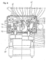
- a bolster 2 is fixed to a frame 1 of a machine press 60.
- a slide 3 is movably mounted within press 60 so that it can be raised and lowered freely.
- Upper and lower dies (not shown) are set in slide 3 and bolster 2, respectively, to perform a pressing operation.
- Slide 3 is movable from a lower position, where it meets bolster 2 to an upper position where it is raised above bolster 2.
- a pair of slide guide rods 5 are fixed to a bottom of slide 3.
- Each of slide guide rods 5 is fitted into a slide guide post 4 which is fixed within frame 1.
- the movement of slide 3 is guided by slide guide rods 5 within guide posts 4.
- the slide guide rods 5 and guide posts 4 ensure that the upper die mounted on slide 3 meets a lower die mounted on bolster 2 at a precise position each time slide 3 is lowered.
- a crank shaft 12 is rotatably connected within frame 1.
- a large end of a connecting rod 13, which has the large end and a small end, is connected to the crank section of crankshaft 12.
- the small end of connecting rod 13 is connected to a first slider 14 via a 16th pin 56.
- First slider 14 is movably held in a first groove 61 which is fixed to frame 1 directly above crankshaft 12.
- First slider 14 is restricted by first groove 61 to vertical movement within first groove 61.
- First slider 14 in turn is connected to a first right link 21 and a first left link 21' via a first pin 31.
- connecting rod 13 and first slider 14 are connected via 16th pin 56, and first right link 21 and first left link 21' are connected to first slider 14 via first pin 31.
- first pin 31 the small end of connecting rod 13 could also be connected to first right link 21 and first left link 21' using a single pin.
- crankshaft 12 is used.
- crankshaft 12 it is also possible to use an eccentric shaft instead of crankshaft 12 to connect to the large end of connecting rod 13.
- crank shaft 12 When crank shaft 12 is rotated, the large end of connecting rod 13 rotates with the eccentric portion of crankshaft 12. As the large end rotates, the small end of connecting rod 13 and first slider 14 is raised and lowered in first groove 61.
- First right link 21 is connected to a 17th link 47 and a third link 23 with a second pin 32.
- the other end of 17th link 47 is connected to a second slider 15 which is mounted in frame 1 above second pin 32.
- Second slider 15 is connected to the other end of 17 th link 47 with a first pivot pin 33.
- Second slider 15 is movably connected in a second groove 62 formed on frame 1. Second groove 62 guides movement of second slider 15 in a horizontal direction.
- One end of second slider 15 is threadably connected to a screw shaft 11.
- a worm wheel 9 is fixed to another end of screw shaft 11. Worm wheel 9 meshes with a worm 8.
- Worm 8 is rotatably connected to frame 1.
- Worm wheel 9 is rotatably supported by cap 10 along an axis of worm wheel 9.
- Cap 10 restricts worm wheel 9 to one longitudinal position but allows it to rotate when worm 8 is rotated.
- worm wheel 9 rotates causing screw shaft 11 to rotate.
- Screw shaft 11 rotates within second slider 15 and the rotational motion is transformed into linear motion by the threads of screw shaft 11. That is, a position of second slider 15 is adjusted along second groove 62 as screw shaft 1 is rotated.
- third link 23 is connected to a plunger 6 and one end of a 15th link 45 with a fifth pin 35.
- Plunger 6 is fixed to an upper portion of slide 3 and is guided by a plunger guide 7 fixed to frame 1. Plunger 6 moves up and down along with slide 3. Therefore, the rotation of crank shaft 12 causes slide 3 to move up and down via connecting rod 13, 17th link 47, third link 23, and plunger 6.
- a bracket 16 is fixed to a shelf of frame 1 above slide 3.
- One end of a 14 th link 44 is connected on bracket 16.
- the other end of 14th link 44 is connected to the center of 15 th link 45 with a 13th pin 53.
- One end of a 16th link 46 is connected to a third pivot pin 54 fixed to frame 1.
- the other end of 16 th link 46 is connected to the upper end of a balance weight 40 with 15th pin 55.
- Balance weight 40 is used as a counter weight to slide 3 making it easier to raise slide 3.
- worm 8 is rotates to cause linear movement of second slider 15.
- the purpose of worm 8 is to change the die height and the stroke length of slide 3.
- worm wheel 9 and screw shaft 11 cause first pivot pin 33 on second slider 15 to be displaced.
- the displacement of first pivot pin 33 changes the pivot point of 17 th link 47.
- the incline angle of 17th link 47, third link third link 23, and first right link 21, which together serve as a toggle link, also changes in response to the displacement of first pivot pin 33.
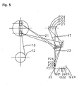
- first pivot pin 33 is moveable in a range of positions from A11 - A16.
- first pivot pin 33 is moved from position A11 to position A16 the upper dead point changes from positions P11 to P16 and the lower dead point changes from Q11 to Q16, respectively.
- the positions of 17 th link 47, third link 23 and first link 21 are shown at the upper and lower positions of first slider 14 at the both extreme pivot pin positions A11 and A16. Since the adjustment to first pivot pin 33 is made from outside press 60, fine tuning of the die height and stroke length of press 60 can be accomplished during operation of press 60.
- the horizontal axis represents the displacement of first pivot pin 33, i.e., the amount of adjustment (ADJ).
- the vertical axis represents the stroke length of the slide (stroke, or St) or the die height (DH).
- Discrete upper dead point positions P11 - P16 are represented by line p and discrete lower dead point positions Q11 - Q16 are represented by line q.
- Line r is a line that is parallel to q starting at point P11.
- the difference between lines p and r illustrates the change in the stroke length as a factor of the amount of adjustment (ADJ).
- ADJ amount of adjustment
- first pivot pin 33 adjustable.
- the initial position of first pivot pin 33 can also be directly fixed anywhere on frame 1.
- a second embodiment of press 60 of the present invention includes second pin 32 positioned outward from plunger 6.
- second pin 32 is positioned inward from plunger 6 (toward the center of the press).
- the second embodiment of press 60 is identical in structure to the first embodiment.
- the horizontal axis represents the amount of displacement of first pivot pin 33, i.e., the amount of adjustment (ADJ).
- the vertical axis represents the stroke length (stroke, or St) of the slide or the die height (DH).
- Discrete upper dead point positions P21 through P24 are represented by line p and discrete lower dead point positions Q21 through Q24 are represented by line q.
- the present invention uses straight links instead of prior art bell-crank shaped links.
- the pivot of the straight links are arranged so that its position is adjustable. Using the described configuration, the distance between the left and right plungers can be decreased. Also, the stroke length of the slide and the lower dead point of the slide is easily adjusted while the press is operating.
Landscapes
- Engineering & Computer Science (AREA)
- Mechanical Engineering (AREA)
- Press Drives And Press Lines (AREA)
- Presses And Accessory Devices Thereof (AREA)
Claims (4)
- Mechanische Presse (60) mit einer Vorrichtung zum Antrieb eines Schlittens (3) in der mechanischen Presse, bestehend aus:wobei ein Ende einer Verbindungsstange (13) mit der Kurbelwelle verbunden ist;einem Gehäuse (1);einer Kurbelwelle (12), die drehbar an dem Gehäuse angeordnet ist;
wobei das andere Ende der Verbindungsstange (13) vertikal und linear geführt und mit dem Gehäuse verbunden ist;
einem Übertragungsmechanismus um die vertikale Bewegung der Verbindungsstange (13) auf den Schlitten (3) zu übertragen;
weiter bestehend aus:wobei die Hublänge und die Höhe des Schlittens abhängig von der Position des ersten Drehzapfens sind.einem ersten Übertragungsmechanismus mit:einem ersten Abschnitt (21) des ersten Übertragungsmechanismusses, der mit dem anderen Ende der Verbindungsstange (13) verbunden ist;einem ersten Drehzapfen (33), der an dem Gehäuse angeordnet ist, wobei die Position des ersten Drehzapfens gegenüber der mechanischen Presse wenigstens in eine erste Position und in eine zweite Position verstellbar ist;einem zweiten Abschnitt (47) des ersten Übertragungsmechanismusses, der drehbar mit dem Drehzapfen (33) verbunden ist;einem Stempel (6), der an dem Schlitten (3) befestigt ist und durch das Gehäuse geführt wird;einem dritten Abschnitt (23) des ersten Übertragungsmechanismusses, der mit dem Oberteil des Stempels (6) verbunden ist, so dass eine Auf- und Abbewegung des ersten Abschnittes in eine Auf- und Abbewegung des Stempels (6) und des Schlittens (3) übersetzt wird; und - Die mechanische Presse von Fig. 1, weiter besitzend einen zweiten Übertragungsmechanismus, wobei der zweite Übertragungsmechanismus um eine Mittellinie des Schlittens (3) symmetrisch zu dem ersten Übertragungsmechanismus ist.
- Die mechanische Presse von Anspruch 1 oder 2, wobei der erste Übertragungsmechanismus weiter einschließt:wobei das erste gerade Verbindungsglied (21) drehbar mit einem Ende des zweiten Verbindungsglieds (47) und einem Ende des dritten Verbindungsglieds (23) verbunden ist;ein erstes Verbindungsglied (21), das mit einem Ende mit dem anderen Ende der Verbindungsstange (13) verbunden ist;einem zweiten Verbindungsglied (47);einem dritten Verbindungsglied (23);
wobei ein anderes Ende des zweiten Verbindungsglieds (47) drehbar mit dem Drehpunkt (33) verbunden ist;
wobei ein anderes Ende des dritten Verbindungsglieds (23) mit dem Stempel verbunden ist;
wobei das eine Ende des ersten Verbindungsglieds der erste Abschnitt, das andere Ende des zweiten Verbindungsglieds der zweite Abschnitt und das andere Ende des dritten Verbindungsglieds der dritte Abschnitt ist. - Die mechanische Presse von Fig. 3, weiter besitzend einen zweiten Verbindungsmechanismus, wobei der zweite Verbindungsmechanismus um eine Mittellinie des Schlittens (3) symmetrisch zu dem ersten Verbindungsmechanismus ist.
Applications Claiming Priority (3)
| Application Number | Priority Date | Filing Date | Title |
|---|---|---|---|
| JP302482/96 | 1996-10-28 | ||
| JP30248296 | 1996-10-28 | ||
| JP8302482A JPH10128597A (ja) | 1996-10-28 | 1996-10-28 | リンクを用いたプレスのスライド駆動装置 |
Publications (3)
| Publication Number | Publication Date |
|---|---|
| EP0838328A2 EP0838328A2 (de) | 1998-04-29 |
| EP0838328A3 EP0838328A3 (de) | 1999-04-14 |
| EP0838328B1 true EP0838328B1 (de) | 2004-09-22 |
Family
ID=17909493
Family Applications (1)
| Application Number | Title | Priority Date | Filing Date |
|---|---|---|---|
| EP97118478A Expired - Lifetime EP0838328B1 (de) | 1996-10-28 | 1997-10-24 | Stösselantriebsvorrichtung für eine Kniehebelpresse |
Country Status (4)
| Country | Link |
|---|---|
| US (1) | US5848568A (de) |
| EP (1) | EP0838328B1 (de) |
| JP (1) | JPH10128597A (de) |
| DE (1) | DE69730795T2 (de) |
Cited By (1)
| Publication number | Priority date | Publication date | Assignee | Title |
|---|---|---|---|---|
| DE102005001878B3 (de) * | 2005-01-14 | 2006-08-03 | Schuler Pressen Gmbh & Co. Kg | Servopresse mit Kniehebelgetriebe |
Families Citing this family (18)
| Publication number | Priority date | Publication date | Assignee | Title |
|---|---|---|---|---|
| ES2137754T3 (es) * | 1997-12-12 | 1999-12-16 | Bruderer Ag | Prensa, especialmente prensa de estampar. |
| JP3451214B2 (ja) * | 1998-07-17 | 2003-09-29 | 株式会社山田ドビー | プレス機 |
| US5998885A (en) * | 1998-09-21 | 1999-12-07 | Ford Global Technologies, Inc. | Propulsion system for a motor vehicle using a bidirectional energy converter |
| JP4404984B2 (ja) * | 1999-03-24 | 2010-01-27 | 株式会社山田ドビー | プレス機 |
| DE19935656A1 (de) * | 1999-07-29 | 2001-02-01 | Schuler Pressen Gmbh & Co | Pressenbaureihe |
| US6405576B1 (en) * | 1999-11-30 | 2002-06-18 | Aida Engineering Co., Ltd. | Linear slide press machine |
| JP2001232497A (ja) * | 2000-02-22 | 2001-08-28 | Aida Eng Ltd | プレス機械のスライド駆動装置 |
| IT1314654B1 (it) * | 2000-03-03 | 2002-12-31 | Copress S R L | Meccanismo di comando per presse con attuazione a doppia ginocchiera |
| JP2001300798A (ja) * | 2000-04-25 | 2001-10-30 | Aida Eng Ltd | プレス機械のストローク調節装置 |
| JP3701005B2 (ja) * | 2000-05-11 | 2005-09-28 | アイダエンジニアリング株式会社 | プレス機械のスライド駆動装置 |
| AUPR387701A0 (en) * | 2001-03-21 | 2001-04-12 | Infamed Limited | Improved spacer device |
| JP2003080397A (ja) * | 2001-09-11 | 2003-03-18 | Yamada Dobby Co Ltd | プレス機 |
| US20040221640A1 (en) * | 2003-05-07 | 2004-11-11 | Shih-Chi Chang | Punching mechanism for punching press with multiple Linking rods |
| DE102010019634B3 (de) * | 2010-05-06 | 2011-11-17 | Multivac Sepp Haggenmüller Gmbh & Co. Kg | Schneideinrichtung für eine Verpackungsmaschine |
| DE102014111683B4 (de) * | 2014-08-15 | 2016-06-30 | Georg Maschinentechnik GmbH & Co. KG | Pressenantrieb für eine Umformvorrichtung |
| ES2664850T5 (es) * | 2015-04-30 | 2023-02-20 | Multivac Haggenmueller Kg | Máquina envasadora por embutición profunda con troqueladora de tiras |
| CN107718626A (zh) * | 2017-11-27 | 2018-02-23 | 苏州韩工机械科技有限公司 | 可调冲压装置 |
| CN115816888A (zh) * | 2022-11-17 | 2023-03-21 | 一重集团大连工程技术有限公司 | 一种多工位压力机 |
Family Cites Families (18)
| Publication number | Priority date | Publication date | Assignee | Title |
|---|---|---|---|---|
| US1696849A (en) * | 1928-12-25 | Bending machine | ||
| US2054428A (en) * | 1934-05-05 | 1936-09-15 | Klocke William | Knuckle-joint type press |
| CH344609A (de) * | 1955-04-18 | 1960-02-15 | Svetsmekano Ab | Vorrichtung zur Änderung des Hubes des Werkzeughalters an Blechschneidemaschine |
| CH383749A (de) * | 1961-03-21 | 1964-10-31 | Leipziger Buchbindereimaschine | Antrieb für Präge- und Stanzmaschinen |
| DE1527037A1 (de) * | 1965-08-09 | 1969-05-08 | Pressen Und Scherenbau Erfurt | Stufenlos verstellbares Hubgetriebe an Blechschneid- und Umformmaschinen |
| US4160409A (en) * | 1974-09-03 | 1979-07-10 | Bruderer Ag | Drive for the movable work component, such as the ram of a press, stamping machine or the like |
| DE2925416C2 (de) * | 1979-06-23 | 1983-02-24 | Werner Ing.(Grad.) 6460 Gelnhausen Leinhaas | Kniehebel-Blechschneidepresse |
| JPH0636469B2 (ja) * | 1988-07-18 | 1994-05-11 | 三菱伸銅株式会社 | 銅張積層配線板の製造方法 |
| JPH02165900A (ja) * | 1988-12-16 | 1990-06-26 | Kiyouri Kogyo Kk | プレス機の下死点補正装置 |
| GB2234196B (en) * | 1989-07-22 | 1993-02-17 | Verson Hme Ltd | Press and method of working material |
| CH684394A5 (de) * | 1991-12-11 | 1994-09-15 | Bruderer Ag | Einwellen-Stanzpresse. |
| DE59303264D1 (de) * | 1993-06-04 | 1996-08-22 | Bruderer Ag | Einwellen-Vierpunkt-Stanzpresse |
| JPH0756148A (ja) * | 1993-08-20 | 1995-03-03 | Toshiba Corp | 液晶表示素子 |
| JP3371231B2 (ja) * | 1993-08-23 | 2003-01-27 | バブコック日立株式会社 | 衝撃波センサユニットと射撃評価システム |
| JPH07121474A (ja) * | 1993-10-21 | 1995-05-12 | Ricoh Co Ltd | 情報処理装置 |
| JP2649318B2 (ja) * | 1993-11-11 | 1997-09-03 | 株式会社山田ドビー | プレス機 |
| JPH08118095A (ja) * | 1994-10-24 | 1996-05-14 | Kiyouri Kogyo Kk | プレス機械の下死点調整機構 |
| JPH08118082A (ja) * | 1994-10-24 | 1996-05-14 | Kiyouri Kogyo Kk | プレス機械 |
-
1996
- 1996-10-28 JP JP8302482A patent/JPH10128597A/ja active Pending
-
1997
- 1997-07-15 US US08/892,803 patent/US5848568A/en not_active Expired - Lifetime
- 1997-10-24 EP EP97118478A patent/EP0838328B1/de not_active Expired - Lifetime
- 1997-10-24 DE DE69730795T patent/DE69730795T2/de not_active Expired - Lifetime
Cited By (1)
| Publication number | Priority date | Publication date | Assignee | Title |
|---|---|---|---|---|
| DE102005001878B3 (de) * | 2005-01-14 | 2006-08-03 | Schuler Pressen Gmbh & Co. Kg | Servopresse mit Kniehebelgetriebe |
Also Published As
| Publication number | Publication date |
|---|---|
| EP0838328A3 (de) | 1999-04-14 |
| JPH10128597A (ja) | 1998-05-19 |
| DE69730795D1 (de) | 2004-10-28 |
| EP0838328A2 (de) | 1998-04-29 |
| US5848568A (en) | 1998-12-15 |
| DE69730795T2 (de) | 2006-02-16 |
Similar Documents
| Publication | Publication Date | Title |
|---|---|---|
| US5848568A (en) | Device for driving a slide in a link press | |
| JP2703097B2 (ja) | 揺動支点型てこ装置および機械装置 | |
| US6012322A (en) | Slide-driving device for knuckle presses | |
| US5287728A (en) | Power transmission device for press machine | |
| US6405576B1 (en) | Linear slide press machine | |
| US4318325A (en) | Press drive arrangement | |
| CN112371786A (zh) | 一种可调节多角度板材折弯装置 | |
| ITMI951266A1 (it) | Sistema di guida per punzone di tipo articolato | |
| EP1175993A2 (de) | Antriebsvorrichtung für Presse | |
| JP2020110839A (ja) | プレス機 | |
| EP1356921B1 (de) | Mechanische Presse | |
| US3687586A (en) | Powder-forming press | |
| CN215435687U (zh) | 具有抚平整理功能的财务凭证装订装置 | |
| JPH0857926A (ja) | 型閉用2重トグル機構を有する射出成形用プレス機 | |
| CN113772170A (zh) | 一种翻转机构 | |
| JP2649318B2 (ja) | プレス機 | |
| JP2002103089A (ja) | プレス機械 | |
| JPH10109194A (ja) | リンクを用いた機械プレスのスライド駆動装置 | |
| US3948134A (en) | Machine tool driving apparatus | |
| US4762062A (en) | Mechanical press | |
| JP2000280094A (ja) | プレス機械 | |
| CN211315007U (zh) | 死点调节的曲柄连杆结构及端子机 | |
| JPH10109192A (ja) | リンクを用いた機械プレスのスライド駆動装置 | |
| EP1223027B1 (de) | Kraftübertragung für Presse | |
| SU522966A1 (ru) | Пресс-автомат с нижним приводом |
Legal Events
| Date | Code | Title | Description |
|---|---|---|---|
| PUAI | Public reference made under article 153(3) epc to a published international application that has entered the european phase |
Free format text: ORIGINAL CODE: 0009012 |
|
| AK | Designated contracting states |
Kind code of ref document: A2 Designated state(s): CH DE GB LI |
|
| AX | Request for extension of the european patent |
Free format text: AL;LT;LV;RO;SI |
|
| PUAL | Search report despatched |
Free format text: ORIGINAL CODE: 0009013 |
|
| AK | Designated contracting states |
Kind code of ref document: A3 Designated state(s): AT BE CH DE DK ES FI FR GB GR IE IT LI LU MC NL PT SE |
|
| AX | Request for extension of the european patent |
Free format text: AL;LT;LV;RO;SI |
|
| 17P | Request for examination filed |
Effective date: 19991012 |
|
| AKX | Designation fees paid |
Free format text: CH DE GB LI |
|
| 17Q | First examination report despatched |
Effective date: 20020724 |
|
| GRAP | Despatch of communication of intention to grant a patent |
Free format text: ORIGINAL CODE: EPIDOSNIGR1 |
|
| GRAS | Grant fee paid |
Free format text: ORIGINAL CODE: EPIDOSNIGR3 |
|
| GRAA | (expected) grant |
Free format text: ORIGINAL CODE: 0009210 |
|
| AK | Designated contracting states |
Kind code of ref document: B1 Designated state(s): CH DE GB LI |
|
| REG | Reference to a national code |
Ref country code: GB Ref legal event code: FG4D |
|
| REG | Reference to a national code |
Ref country code: CH Ref legal event code: EP |
|
| REF | Corresponds to: |
Ref document number: 69730795 Country of ref document: DE Date of ref document: 20041028 Kind code of ref document: P |
|
| REG | Reference to a national code |
Ref country code: CH Ref legal event code: NV Representative=s name: BUGNION S.A. |
|
| PLBE | No opposition filed within time limit |
Free format text: ORIGINAL CODE: 0009261 |
|
| STAA | Information on the status of an ep patent application or granted ep patent |
Free format text: STATUS: NO OPPOSITION FILED WITHIN TIME LIMIT |
|
| 26N | No opposition filed |
Effective date: 20050623 |
|
| PGFP | Annual fee paid to national office [announced via postgrant information from national office to epo] |
Ref country code: GB Payment date: 20090914 Year of fee payment: 13 |
|
| PGFP | Annual fee paid to national office [announced via postgrant information from national office to epo] |
Ref country code: DE Payment date: 20091030 Year of fee payment: 13 Ref country code: CH Payment date: 20091026 Year of fee payment: 13 |
|
| REG | Reference to a national code |
Ref country code: CH Ref legal event code: PL |
|
| GBPC | Gb: european patent ceased through non-payment of renewal fee |
Effective date: 20101024 |
|
| PG25 | Lapsed in a contracting state [announced via postgrant information from national office to epo] |
Ref country code: CH Free format text: LAPSE BECAUSE OF NON-PAYMENT OF DUE FEES Effective date: 20101031 Ref country code: LI Free format text: LAPSE BECAUSE OF NON-PAYMENT OF DUE FEES Effective date: 20101031 |
|
| REG | Reference to a national code |
Ref country code: DE Ref legal event code: R119 Ref document number: 69730795 Country of ref document: DE Effective date: 20110502 |
|
| PG25 | Lapsed in a contracting state [announced via postgrant information from national office to epo] |
Ref country code: GB Free format text: LAPSE BECAUSE OF NON-PAYMENT OF DUE FEES Effective date: 20101024 |
|
| PG25 | Lapsed in a contracting state [announced via postgrant information from national office to epo] |
Ref country code: DE Free format text: LAPSE BECAUSE OF NON-PAYMENT OF DUE FEES Effective date: 20110502 |