EP0838941A2 - Appareil de traitement d'image, appareil de sortie d'image, procédé pour commander celui-ci et système de sortie d'image - Google Patents
Appareil de traitement d'image, appareil de sortie d'image, procédé pour commander celui-ci et système de sortie d'image Download PDFInfo
- Publication number
- EP0838941A2 EP0838941A2 EP97118266A EP97118266A EP0838941A2 EP 0838941 A2 EP0838941 A2 EP 0838941A2 EP 97118266 A EP97118266 A EP 97118266A EP 97118266 A EP97118266 A EP 97118266A EP 0838941 A2 EP0838941 A2 EP 0838941A2
- Authority
- EP
- European Patent Office
- Prior art keywords
- image
- image output
- output apparatus
- information
- processing apparatus
- Prior art date
- Legal status (The legal status is an assumption and is not a legal conclusion. Google has not performed a legal analysis and makes no representation as to the accuracy of the status listed.)
- Granted
Links
- 230000010365 information processing Effects 0.000 title claims description 31
- 238000000034 method Methods 0.000 title claims description 15
- 238000012937 correction Methods 0.000 claims abstract description 103
- 238000012545 processing Methods 0.000 claims description 20
- 230000008859 change Effects 0.000 claims description 14
- 230000015572 biosynthetic process Effects 0.000 claims description 12
- 238000005259 measurement Methods 0.000 claims description 7
- 238000004891 communication Methods 0.000 claims description 4
- 230000004044 response Effects 0.000 claims description 4
- 238000012546 transfer Methods 0.000 claims description 2
- 230000006870 function Effects 0.000 description 15
- 238000010586 diagram Methods 0.000 description 10
- 230000005540 biological transmission Effects 0.000 description 4
- 230000007246 mechanism Effects 0.000 description 4
- 230000008569 process Effects 0.000 description 3
- 238000010276 construction Methods 0.000 description 2
- 230000007423 decrease Effects 0.000 description 2
- 230000002457 bidirectional effect Effects 0.000 description 1
- 230000015556 catabolic process Effects 0.000 description 1
- 238000006243 chemical reaction Methods 0.000 description 1
- 238000006731 degradation reaction Methods 0.000 description 1
- 230000007613 environmental effect Effects 0.000 description 1
- 238000012986 modification Methods 0.000 description 1
- 230000004048 modification Effects 0.000 description 1
- 230000003287 optical effect Effects 0.000 description 1
Images


Classifications
-
- H—ELECTRICITY
- H04—ELECTRIC COMMUNICATION TECHNIQUE
- H04N—PICTORIAL COMMUNICATION, e.g. TELEVISION
- H04N1/00—Scanning, transmission or reproduction of documents or the like, e.g. facsimile transmission; Details thereof
- H04N1/40—Picture signal circuits
- H04N1/407—Control or modification of tonal gradation or of extreme levels, e.g. background level
- H04N1/4076—Control or modification of tonal gradation or of extreme levels, e.g. background level dependent on references outside the picture
- H04N1/4078—Control or modification of tonal gradation or of extreme levels, e.g. background level dependent on references outside the picture using gradational references, e.g. grey-scale test pattern analysis
Definitions
- This invention relates to an information processing apparatus, an image output apparatus, a method of controlling the same and an image forming system which includes these apparatus.
- a laser printer forms an image by forming a toner image and fixing the toner image on a recording medium
- an ink-jet printer forms an image by jetting ink onto a recording medium.
- the conventional calibration mechanism is provided on the printer side.
- the information processing capability of the printer is inferior to that of a computer and it is becoming increasing difficult for such a printer to satisfy the recent demand for higher quality images.
- incorporating the entire calibration mechanism in the printer is a cause of higher printer cost.
- an object of the present invention is to divide the function for correcting the image quality of an output image between the image processing apparatus and the image output apparatus.
- an information processing apparatus for supplying image information to an image output apparatus and causing the image output apparatus to form an image, comprising: acquisition means for acquiring actually measured density values of a sample image formed by the image output apparatus; and creation means for creating a correction rule, which is for correcting density of the image information, based upon the actually measured density values acquired from the acquisition means.
- an image output system comprising an information processing apparatus and an image output apparatus connected together, the image output apparatus comprising: image forming means for forming an image based upon image information supplied by the information processing apparatus; control means for causing the image forming means to form a sample image; and measurement means for measuring density of the sample image formed; and the information processing apparatus comprises: acquisition means for acquiring actually measured density values of the sample image, which has been formed by the image output apparatus, from the image output apparatus; creation means for creating a correction rule, which is for correcting density of the image information, based upon the actually measured density values acquired from the acquisition means; and supply means for supplying the image information to the image output apparatus; wherein density of the image information is corrected by the image output apparatus or the information processing apparatus based upon the correction rule, whereby an output density characteristic of the image forming means is corrected appropriately.
- an image output apparatus having means for connecting the image output apparatus to an information processing apparatus via a communiccation network, comprising: image forming means for forming an image based upon image information supplied by the information processing apparatus; control means for causing the image forming means to form a sample image based upon information concerning formation of the sample image supplied by the image processing apparatus; measurement means for measuring the sample image formed; and transmitting means for transmitting the measured value of the sample image to the information processing apparatus.
- the foregoing object is attained by providing a method of controlling an iamge otput apparatus having image forming means for forming an image based upon image information supplied by an information processing apparatus via a communication network, comprising: controlling step of causing the image forming means to orm a sample image based upon the information concerning formation of the sample image supplied by the image processing apparatus; a measurement step measuring the sample image formed; and a transfer step of transferring the measured value of the sample image to the information procdessing apparatus.
- Fig. 1 is a block diagram illustrating the construction of printer system according to an embodiment of the present invention.
- the printer system comprises a computer 1, which is typified by a personal computer, and a printer 2 connected by a bidirectional interface 3.
- the computer 1 creates a document (which may include figures and tables, etc.) file, produces print data in, say, page description language, based upon this document file, and sends the print data to the printer 2.
- a computer 1 executes calibration in response to a calibration request from the printer 2. Calibration in this embodiment is achieved by correcting, in dependence upon the status of the printer 2 when print data is produced, a grayscale correction table which is used to convert a logical grayscale value to an appropriate grayscale value conforming to the status of the printer 2.
- An application program 11 is software for creating a document file.
- the application program 11 would include a GDI.
- a data processor 12 On the basis of a document file supplied by the application 11, a data processor 12 produces print data to be sent to the printer 2. At this time the data processor 12 refers to a grayscale correction table 16, which has been stored on a storage medium 15, to convert a logical grayscale value specified in the document file to an appropriate grayscale value.
- An interface controller 13 controls an exchange of data with the printer 2.
- the interface controller 13 transmits the print data produced in the data processor 12 to the printer 2, receives a calibration request from the printer 2 and receives data related to calibration from the printer 2.
- a density correction processor 14 responds to the calibration request by creating the grayscale correction table 16 based upon an actual density value acquired from the printer 2 (the actual density value is density obtained by forming a sample image in the printer 2 and measuring the sample image) and storing the grayscale correction table 16 on the storage medium 15.
- the latter ideally is constituted by e.g. a hard disk, SRAM or DRAM, etc.
- the printer 2 has a printer controller 21 and a printer engine 22.
- the printer controller 21 receives print data sent from the computer 1, converts the print data to bitmap data and supplies the bitmap data to the printer engine 22, where the image is formed on the recording medium (e.g. recording paper). Further, the printer controller 21 senses an environmental change (e.g. a change in temperature) and consumption of components (e.g. a decline in amount of remaining toner), and issues a calibration request to the computer 1 if a fluctuation in the sensed value is large enough to require calibration. On the basis of grayscale correction data (logical density values) supplied by the computer 1 in response to the calibration request, the printer controller 21 forms a sample image and sends the computer 1 the result (actual density values) of measuring the density of the sample image.
- grayscale correction data logical density values
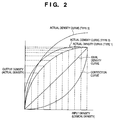
- Fig. 2 is a graph showing an example of the relationship between an input density value (logical density value) and output density value (actual density value) in the printer 2.
- a logical density value specified in a document file produced in a computer and an actual density value representing the actual density of an image formed by the printer do not agree and it is required, therefore, that the logical density value be subjected to a suitable correction.
- the amount of this correction increases depending upon the status of the printer engine, e.g. a change in the environment.
- An actual density curve indicating the relationship between input density (logical density) and actual density differs depending upon the type of printer as a matter of course but also differs depending upon the environment of use and conditions of use even for one and the same printer.
- Fig. 2 Three types (Types 1 ⁇ 3) of actual density curves are shown in Fig. 2 for reference purposes. Density that has not undergone a grayscale correction in the data processor 12, namely logical density, is plotted along the horizontal axis. Density of the output image corresponding to the logical density, namely the actual density, is plotted along the vertical axis.
- the actual density curves are convex and the intermediate density portions of the curves tend to represent a density darker than that intended.
- an output image having an ideal characteristic (a linear density characteristic), which is indicated by the ideal density curve shown in Fig. 2, from the printer 2 having the convex characteristic, it is required that the logical density be corrected by a concave correction curve.
- the illustrated correction curve is one that corresponds to the actual density curve of Type 1.
- the computer 1 generates grayscale correction data of predetermined logical densities (e.g. 10, 20, 30 ⁇ 100%) in dependence upon the calibration request from the printer 2 and supplies this data to the printer 2.
- the printer 2 forms a sample image based upon the grayscale correction data and measures the density of the sample image by a density sensor 22a, whereby actual density can be obtained.
- the computer 1 is capable of creating the grayscale correction table 16 having a conversion rule of the kind indicated by "correction curve" in Fig. 2, by way of example.
- formation of the sample image and measurement of density in the printer 2 may be performed by actually forming the sample image on the recording medium (e.g. recording paper) and measuring the density of this image.
- the sample image may be formed on a photosensitive drum and the density of the sample image on the photosensitive drum may be measured.
- the creation of the grayscale correction table in the density correction processor 14 is performed by processing in two stages. Specifically, the density correction processor 14 first establishes correspondence between logical density and actual density in relation to tones included in the sample image and creates a first grayscale correction table (see Fig. 3) for correcting the logical density appropriately. Second, on the basis of the first grayscale correction table, the density correction processor 14 creates a second grayscale correction table (the grayscale correction table 16) (see Fig. 4) produced by interpolating data representing tones not contained in the sample image.
- Fig. 3 is a diagram showing an example of the first grayscale correction table.
- the leftmost column in Fig. 3 shows logical density values in grayscale correction data produced in the data processor 12 and supplied to the printer 2.
- the logical density values are partitioned at increments of 10°/C over a range of 0 to 100%.
- the center column in Fig. 3 shows actual density values obtained by measuring the sample image produced by the printer 2 based upon the grayscale correction data.
- the rightmost column in Fig. 3 shows density correction values obtained by dividing the logical density values by the actual density values.
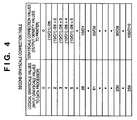
- Fig. 4 is a diagram showing an example of the second grayscale correction table (the grayscale correction table 16).
- the second grayscale correction table is produced in the density correction processor 14 based upon the first grayscale correction table.
- the left column in Fig. 4 shows the logical grayscale values in a document file produced by the application program 11.
- the right column in Fig. 4 shows the output grayscale values corresponding to the entered logical grayscale values, namely the grayscale values in the print data supplied to printer 2.
- the second grayscale correction table uses the density correction values 10/D1, 20/D2, ⁇ , 90/D9, 100/D10 in the first grayscale correction table as is in relation to the logical grayscale values 26, 51, ⁇ , 230, 255 (here the print data supplied to the printer 2 is assumed to have the 256 gray levels of 0 to 255) corresponding to the logical density values 10, 20, ⁇ , 90, 100% of the first grayscale correction table shown in Fig. 3. With regard to grayscale correction values corresponding to the other logical grayscale values, these are interpolated using the grayscale correction values for the logical grayscale values 26, 51, ⁇ , 230, 255.
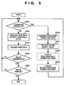
- Fig. 5 is a flowchart illustrating an example of operation of the computer 1.
- the processing indicated by the flowchart of Fig. 5 is controlled by the controller 17 and is started in a case where a print command has been received from the application program 11 or in a case where a calibration request is received from the printer 2.
- the controller 17 determines whether calibration has been requested or not.
- Examples of methods through which the printer 2 notifies the computer 1 of a calibration request include sending the computer 1 a predetermined command (e.g. a calibration request command) or providing the communication cable 3 with a special signal line and giving notification of the request by the signal level of this signal line, etc.
- step S506 if a calibration request has been recognized at step S501 and to step S502 if a calibration request is not recognized (if printing has not yet been completed).
- Grayscale correction data is sent to the printer 2 at step S506.
- the printer 2 forms a sample image based upon the grayscale correction data, measures the density of the sample image by the density sensor 22a and notifies the computer 1 of the result (actual density value). It should be noted that transmission of actual density values may simply be requested without sending grayscale correction data to the printer 2 at step S506. In such case, however, it would be necessary for the computer 1 to recognize the logical density value, which corresponds to the density value of the sample image formed by the printer, as by receiving the logical density value along with the actual density value at step S507.
- step S507 The actual density value is received from the computer 1 at step S507.
- step S508 at which the first grayscale correction table is produced by the grayscale correction processor 14 based upon the actual density value received, and then by step S509, at which the second grayscale correction table (grayscale correction table 16) is produced by the grayscale correction processor 14 using the first grayscale correction table.
- step S509 at which the second grayscale correction table (grayscale correction table 16) is produced by the grayscale correction processor 14 using the first grayscale correction table.
- the print data is produced at step S502 by the data processor 12 while the data processor 12 corrects the logical grayscale value to the appropriate grayscale value by referring to the second grayscale correction table (grayscale correction table 16) on the basis of the document file supplied from the application program 11.
- the second grayscale correction table grayscale correction table 16
- the print data produced is transmitted to the printer 2 via the interface controller 13 at step S503.
- step S504 It is determined at step S504 whether transmission of print data per unit (e.g. page unit) has been completed.
- the program proceeds to step S505 if transmission has been completed and returns to step S501 if transmission has not been completed.
- step S505 It is determined at step S505 whether printing specified by the application program 11 has been completed. If printing has been completed, the processing indicated by this flowchart is terminated; otherwise, the program returns to step S501.
- the processing may be performed on the side of the computer 2.
- the information relating to this table would be transferred to the printer 2, the information would be stored in memory means (not shown) in the printer controller 21, and the information would be referred to at the time of printing.
- Fig. 6 is a flowchart illustrating a specific example of the processing (step S509) for creating the second grayscale correction table (grayscale correction table 16).
- the density correction values (10/D1, 20/D2, ⁇ , 90/D9, 100/D10) in the first grayscale correction table are adopted as the grayscale correction values for the logical grayscale values corresponding to the logical density values.
- the accuracy of a grayscale correction value set here is based upon the actual density value actually measured in the printer 2.
- step S603 at which missing portions, namely grayscale correction values (e.g. 1 ⁇ 25, 27 ⁇ 50) relating to density for which a sample image has not been formed and density not measured, are interpolated.
- Fig. 7 is a flowchart illustrating an example of the calibration-related operation of the printer 2. The processing indicated by this flowchart is controlled by the printer controller 21.
- step S701 a change in environment (e.g., a change in temperature or a decline in amount of remaining toner), which is a factor that makes calibration necessary, is sensed by the sensor 22b. It is then determined at step S702 whether the change in environment is of such a degree that would require calibration. (For example, the amount of change in environment is compared with a preset value.) The program proceeds to step S703 if it is determined that calibration is required and returns to step S701 if it is determined that calibration is not required.
- a change in environment e.g., a change in temperature or a decline in amount of remaining toner
- step S703 at which a calibration request is sent to the computer 1 (in response to which the processing shown in the flowchart of Fig. 5 is started), and then by step S704, at which the grayscale correction data is received from the computer 1 (this corresponds to step S506).
- step S705 a sample image is formed based upon the grayscale correction data.
- the density of the sample image formed is measured by the density sensor 22a at step S706, after which the measured density is transmitted to the computer 1 as an actual density value at step S707 (which corresponds to step S507).
- the grayscale correction table 16 is updated on the side of computer 1, thereby completing the calibration operation.
- grayscale correction values of portions not actually measured may be determined by interpolation processing that is based upon a curve.
- Interpolation processing in this case may employ a Bézier curve, quadratic curve or cubic curve.
- an arrangement may be adopted in which grayscale correction tables of a plurality of types are registered in the computer 1 in advance and any one of these grayscale correction tables is selected based upon an actual density value acquired from the printer 2.
- An effective method for use in this case includes obtaining one or several grayscale correction values corresponding to an acquired actual density value, comparing this grayscale correction value with a corresponding grayscale correction value in the grayscale correction tables prepared beforehand, and selecting the grayscale correction table for which the difference between the two values is smallest.
- the number or values of logical density values which prevail when a sample image is formed can be selected at will in dependence upon the characteristics of the printer, user preference, etc.
- the present invention can be applied to a system constituted by a plurality of devices (e.g., a host computer, interface, reader, printer, etc.) or to an apparatus comprising a single device (e.g., a copier or facsimile machine, etc.).
- a host computer e.g., a host computer, interface, reader, printer, etc.
- an apparatus e.g., a copier or facsimile machine, etc.
- the object of the present invention can also be achieved by providing a storage medium storing the program codes of the software for performing the aforesaid functions of the foregoing embodiments to a system or an apparatus, reading the program codes with a computer (e.g., a CPU or MPU) of the system or apparatus from the storage medium, and then executing the program.
- a computer e.g., a CPU or MPU
- the program codes read from the storage medium implement the novel functions of the invention, and the storage medium storing the program codes constitutes the invention.
- the storage medium such as a floppy disk, hard disk, optical disk, magneto-optical disk, CD-ROM, CD-R, magnetic tape, non-volatile type memory card or ROM can be used to provide the program codes.
- the present invention covers a case where an operating system (OS) or the like working on the computer performs a part of or the entire process in accordance with the designation of program codes and implements the functions according to the embodiment.
- OS operating system
- the present invention further covers a case where, after the program codes read from the storage medium are written in a function extension board inserted into the computer or in a memory provided in a function extension unit connected to the computer, a CPU or the like contained in the function extension board or function extension unit performs a part of or the entire process in accordance with the designation of program codes and implements the function of the above embodiments.
- Fig. 8 is a diagram showing an example of a memory medium storing program codes for implementing functions of the computer 1 by software.
- a code 801 of a step for acquiring an actually measured density value corresponds to step S507, by way of example.
- a code 802 of a step for creating a correction rule corresponds to e.g. steps S508 and S509.
- a code 803 of a step for correcting the density of image information corresponds to e.g. step S509, the data processor 12 and the density correction table 16, etc.
- Fig. 9 is a diagram showing an example of a memory medium storing program codes for implementing functions of the printer 2 by software.
- the printer 2 can be controlled by causing a CPU (not shown) within the printer controller 21 to operate based upon the program codes stored on this memory medium.
- a code 901 of a calibration request step corresponds to e.g. steps S701 and S702
- a code 902 of a sample image formation step corresponds to e.g. steps S704 and S705
- a code 903 of a step for measuring the density of a sample image corresponds to e.g. step S706
- a code 904 of a notification step for notifying the computer 1 of the measured density of the sample image corresponds to e.g. step S707.
- the function for correcting the image quality of an output image is distributed between an image processing apparatus and an image output apparatus.
- the processing capability of the information processing apparatus can be utilized effectively.
- the functions of the image output apparatus can be simplified.
- a printer sends a calibration request to a computer upon sensing the need for calibration.
- the computer supplies the printer with data (logical density values) for a grayscale correction.
- the printer forms a sample image, measures the density (actual density values) of the sample image and notifies the computer of the actual density values.
- the computer creates a grayscale correction table (executes calibration) serving as a rule for correcting the tonality of image information.
- the computer corrects the tonality of the image information based upon the grayscale correction table and supplies the corrected results to the printer.
Landscapes
- Engineering & Computer Science (AREA)
- Multimedia (AREA)
- Signal Processing (AREA)
- Facsimile Image Signal Circuits (AREA)
- Color, Gradation (AREA)
- Image Processing (AREA)
- Image Input (AREA)
- Controls And Circuits For Display Device (AREA)
- Accessory Devices And Overall Control Thereof (AREA)
- Dot-Matrix Printers And Others (AREA)
Applications Claiming Priority (6)
| Application Number | Priority Date | Filing Date | Title |
|---|---|---|---|
| JP279428/96 | 1996-10-22 | ||
| JP27942896 | 1996-10-22 | ||
| JP27942896 | 1996-10-22 | ||
| JP9246737A JPH10181102A (ja) | 1996-10-22 | 1997-09-11 | 情報処理装置及び画像出力装置及びそれらの制御方法及び画像出力システム |
| JP246737/97 | 1997-09-11 | ||
| JP24673797 | 1997-09-11 |
Publications (3)
| Publication Number | Publication Date |
|---|---|
| EP0838941A2 true EP0838941A2 (fr) | 1998-04-29 |
| EP0838941A3 EP0838941A3 (fr) | 1999-02-10 |
| EP0838941B1 EP0838941B1 (fr) | 2003-07-02 |
Family
ID=26537886
Family Applications (1)
| Application Number | Title | Priority Date | Filing Date |
|---|---|---|---|
| EP97118266A Expired - Lifetime EP0838941B1 (fr) | 1996-10-22 | 1997-10-21 | Appareil de traitement d'image, appareil de sortie d'image, procédé pour commander celui-ci et système de sortie d'image |
Country Status (4)
| Country | Link |
|---|---|
| US (1) | US6046820A (fr) |
| EP (1) | EP0838941B1 (fr) |
| JP (1) | JPH10181102A (fr) |
| DE (1) | DE69723201T2 (fr) |
Cited By (1)
| Publication number | Priority date | Publication date | Assignee | Title |
|---|---|---|---|---|
| EP2731324A3 (fr) * | 2012-11-12 | 2016-10-26 | Samsung Electronics Co., Ltd | Appareil de formation d'image et son procédé de formation d'image, appareil hôte et son procédé de commande de formation d'image et procédé de formation d'image de système de formation d'image |
Families Citing this family (31)
| Publication number | Priority date | Publication date | Assignee | Title |
|---|---|---|---|---|
| US6236463B1 (en) * | 1997-01-17 | 2001-05-22 | Moore U.S.A., Inc. | Generating high speed variable information printed multiple page documents |
| JPH11289454A (ja) * | 1997-11-28 | 1999-10-19 | Canon Inc | 画像処理方法および画像処理装置およびコンピュータが読み出し可能なプログラムを格納した記憶媒体 |
| JP3787427B2 (ja) * | 1997-11-28 | 2006-06-21 | キヤノン株式会社 | プリンタサーバのデータ処理方法及び記憶媒体 |
| US6256111B1 (en) * | 1998-06-19 | 2001-07-03 | International Business Machines Corporation | Calibrating digital halftoning algorithms with multiple personalities |
| US6480625B1 (en) * | 1998-07-14 | 2002-11-12 | Fuji Photo Film Co., Ltd. | Methods for correcting density characteristic and color |
| JP3492220B2 (ja) | 1998-11-18 | 2004-02-03 | キヤノン株式会社 | 情報処理装置および印刷制御方法 |
| US6344902B1 (en) * | 1999-01-19 | 2002-02-05 | Xerox Corporation | Apparatus and method for using feedback and feedforward in the generation of presentation images in a distributed digital image processing system |
| US6738150B1 (en) * | 1999-04-14 | 2004-05-18 | Hewlett-Packard Development Company, L.P. | Methods and systems for processing image data |
| US6934053B1 (en) * | 2000-01-19 | 2005-08-23 | Xerox Corporation | methods for producing device and illumination independent color reproduction |
| US10915296B2 (en) | 2000-11-01 | 2021-02-09 | Flexiworld Technologies, Inc. | Information apparatus that includes a touch sensitive screen interface for managing or replying to e-mails |
| US11467856B2 (en) * | 2002-12-12 | 2022-10-11 | Flexiworld Technologies, Inc. | Portable USB device for internet access service |
| US11204729B2 (en) | 2000-11-01 | 2021-12-21 | Flexiworld Technologies, Inc. | Internet based digital content services for pervasively providing protected digital content to smart devices based on having subscribed to the digital content service |
| US10860290B2 (en) | 2000-11-01 | 2020-12-08 | Flexiworld Technologies, Inc. | Mobile information apparatuses that include a digital camera, a touch sensitive screen interface, support for voice activated commands, and a wireless communication chip or chipset supporting IEEE 802.11 |
| US20020051200A1 (en) | 2000-11-01 | 2002-05-02 | Chang William Ho | Controller for device-to-device pervasive digital output |
| DE10056060A1 (de) * | 2000-11-11 | 2002-05-23 | Best Gmbh | Verfahren zum Überwachen von mindestens einem Druckparameter eines Druckers, Verfahren zum Ermitteln und Senden von mindestens einem Druckparamter eines Druckers, Drucksystem und Drucker |
| US7953818B2 (en) | 2000-11-20 | 2011-05-31 | Flexiworld Technologies, Inc. | Output device and system for rendering digital content |
| US20020097417A1 (en) | 2001-01-19 | 2002-07-25 | Chang William Ho | System for universal data output |
| JP2004074561A (ja) * | 2002-08-16 | 2004-03-11 | Canon Inc | カラー画像処理装置及び画像出力方法 |
| US7908401B2 (en) * | 2002-12-12 | 2011-03-15 | Flexiworld Technology, Inc. | Method and device for wireless communication between computing devices |
| JP4458234B2 (ja) * | 2002-12-27 | 2010-04-28 | セイコーエプソン株式会社 | 印刷制御装置、印刷制御方法および印刷制御プログラム |
| US20040165024A1 (en) * | 2003-02-21 | 2004-08-26 | Ferran Vilanova | Economical method & apparatus for objectively fixing error thresholds and checking color accuracy |
| JP3956887B2 (ja) * | 2003-04-10 | 2007-08-08 | セイコーエプソン株式会社 | 画像処理装置および画像処理方法並びに画像処理プログラム |
| WO2004093149A2 (fr) * | 2003-04-11 | 2004-10-28 | Flexiworld Technologies, Inc. | Execution automatique d'un composant de memoire de circuit integre |
| JP4073905B2 (ja) * | 2004-10-25 | 2008-04-09 | シャープ株式会社 | 画像処理装置、画像形成装置、画像形成システム、画像形成プログラム、画像処理プログラムおよびコンピュータ読取可能な記録媒体 |
| US7162172B2 (en) * | 2004-11-30 | 2007-01-09 | Xerox Corporation | Semi-automatic image quality adjustment for multiple marking engine systems |
| JP2007076165A (ja) * | 2005-09-14 | 2007-03-29 | Canon Inc | 画像形成装置、その制御方法、制御プログラム及び画像形成システム |
| JP2007151075A (ja) * | 2005-10-31 | 2007-06-14 | Seiko Epson Corp | 印刷装置、印刷方法、画像処理装置、画像処理方法、印刷プログラム、画像処理プログラム、及び記録媒体 |
| US8049922B2 (en) * | 2005-11-30 | 2011-11-01 | Kabushiki Kaisha Toshiba | Image forming apparatus and printing method for creating a combined image |
| JP4363412B2 (ja) | 2006-05-11 | 2009-11-11 | ブラザー工業株式会社 | 画像形成装置、印刷制御プログラム、アプリケーションプログラム、及び、印刷システム |
| US7800777B2 (en) * | 2006-05-12 | 2010-09-21 | Xerox Corporation | Automatic image quality control of marking processes |
| US8799769B2 (en) * | 2011-02-08 | 2014-08-05 | Ebay Inc. | Application above-the-fold rendering measurements |
Family Cites Families (9)
| Publication number | Priority date | Publication date | Assignee | Title |
|---|---|---|---|---|
| US4710785A (en) * | 1986-12-12 | 1987-12-01 | Eastman Kodak Company | Process control for electrostatographic machine |
| US5313291A (en) * | 1991-11-25 | 1994-05-17 | Xerox Corporation | Method for matching color prints to color images on a monitor screen |
| JPH06115152A (ja) * | 1992-10-07 | 1994-04-26 | Fuji Photo Film Co Ltd | 光感熱記録における濃度補正方法 |
| ATE185321T1 (de) * | 1993-07-30 | 1999-10-15 | Canon Kk | Bildausgabeanlage und bilderzeugungsgerät zur korrektur von ungleichmässigkeiten in der dichte |
| JP3059615B2 (ja) * | 1993-10-27 | 2000-07-04 | キヤノン株式会社 | 印刷システム及び印刷制御装置及び制御方法 |
| JP3703162B2 (ja) * | 1994-04-22 | 2005-10-05 | キヤノン株式会社 | 画像形成装置 |
| JP3282404B2 (ja) * | 1994-09-26 | 2002-05-13 | ミノルタ株式会社 | 画像形成装置 |
| US5696604A (en) * | 1995-01-04 | 1997-12-09 | Xerox Corporation | Analytical halftone dot construction for a hyperacuity printer |
| US5734407A (en) * | 1995-03-31 | 1998-03-31 | Fuji Xerox Co., Ltd. | Image quality control at restart of image forming apparatus |
-
1997
- 1997-09-11 JP JP9246737A patent/JPH10181102A/ja active Pending
- 1997-10-21 EP EP97118266A patent/EP0838941B1/fr not_active Expired - Lifetime
- 1997-10-21 DE DE69723201T patent/DE69723201T2/de not_active Expired - Lifetime
- 1997-10-22 US US08/954,931 patent/US6046820A/en not_active Expired - Lifetime
Cited By (2)
| Publication number | Priority date | Publication date | Assignee | Title |
|---|---|---|---|---|
| EP2731324A3 (fr) * | 2012-11-12 | 2016-10-26 | Samsung Electronics Co., Ltd | Appareil de formation d'image et son procédé de formation d'image, appareil hôte et son procédé de commande de formation d'image et procédé de formation d'image de système de formation d'image |
| US10013225B2 (en) | 2012-11-12 | 2018-07-03 | S-Printing Solution Co., Ltd. | Image forming apparatus and image forming method thereof to generate binary print data external host apparatus |
Also Published As
| Publication number | Publication date |
|---|---|
| EP0838941B1 (fr) | 2003-07-02 |
| HK1010298A1 (en) | 1999-06-17 |
| JPH10181102A (ja) | 1998-07-07 |
| DE69723201T2 (de) | 2004-05-27 |
| DE69723201D1 (de) | 2003-08-07 |
| EP0838941A3 (fr) | 1999-02-10 |
| US6046820A (en) | 2000-04-04 |
Similar Documents
| Publication | Publication Date | Title |
|---|---|---|
| US6046820A (en) | Image forming device and computer which share the generation of a function for correcting image data based on an image forming condition of the image forming device | |
| US6160968A (en) | Printing method and image processing method for performing printing during which calibration of printing apparatus is executed | |
| US8107142B2 (en) | Image processing apparatus, image processing method, and program product for executing the method | |
| CN102019775A (zh) | 用于多种介质的彩色打印机校准 | |
| US6885474B2 (en) | Image processing apparatus and method and memory medium | |
| US6023344A (en) | Image processing apparatus and method | |
| KR101052749B1 (ko) | 화상 형성 시스템 | |
| JP2000155653A (ja) | 情報処理装置および印刷制御方法 | |
| US8699082B2 (en) | Apparatus to control printing density in image forming device and method thereof | |
| US20090208235A1 (en) | Terminal device, image forming apparatus, and printing system having the same, and printing method thereof | |
| US7178891B2 (en) | Print control apparatus, print control method, print system, and program | |
| US7403303B2 (en) | Printing system and printing method | |
| HK1010298B (en) | Information processing apparatus, image output apparatus, method of controlling same, and image output system | |
| US8184320B2 (en) | Printing control apparatus to control printing operation, printing control system, and methods thereof | |
| US7259892B2 (en) | Printer correcting apparatus and method of controlling same | |
| JP3618985B2 (ja) | 画像処理装置、印刷システムおよび濃度補正処理設定方法 | |
| WO2005059822A2 (fr) | Procede, appareil et systeme de correction de donnees image | |
| US5151973A (en) | Printing apparatus and information processing apparatus using the same | |
| JP2003345074A (ja) | 画像処理システムおよびキャリブレーション方法 | |
| US20060092445A1 (en) | Image processing device, image processing method, and program | |
| JPH1016304A (ja) | 画像出力装置及び画像処理装置及びそれらの方法及び濃度補正方法 | |
| US20240111979A1 (en) | Information processing apparatus, image forming apparatus, and work estimating method that allows objective determination of estimation of work related to printing | |
| JP2001026170A (ja) | 画像処理装置および画像処理方法 | |
| JPH1073978A (ja) | 画像処理装置およびその方法、並びに、記録媒体 | |
| JPH1169099A (ja) | 画像形成装置 |
Legal Events
| Date | Code | Title | Description |
|---|---|---|---|
| PUAI | Public reference made under article 153(3) epc to a published international application that has entered the european phase |
Free format text: ORIGINAL CODE: 0009012 |
|
| AK | Designated contracting states |
Kind code of ref document: A2 Designated state(s): DE FR GB |
|
| PUAL | Search report despatched |
Free format text: ORIGINAL CODE: 0009013 |
|
| AK | Designated contracting states |
Kind code of ref document: A3 Designated state(s): AT BE CH DE DK ES FI FR GB GR IE IT LI LU MC NL PT SE |
|
| 17P | Request for examination filed |
Effective date: 19990706 |
|
| AKX | Designation fees paid |
Free format text: DE FR GB |
|
| 17Q | First examination report despatched |
Effective date: 20001204 |
|
| GRAG | Despatch of communication of intention to grant |
Free format text: ORIGINAL CODE: EPIDOS AGRA |
|
| GRAG | Despatch of communication of intention to grant |
Free format text: ORIGINAL CODE: EPIDOS AGRA |
|
| GRAH | Despatch of communication of intention to grant a patent |
Free format text: ORIGINAL CODE: EPIDOS IGRA |
|
| GRAH | Despatch of communication of intention to grant a patent |
Free format text: ORIGINAL CODE: EPIDOS IGRA |
|
| GRAA | (expected) grant |
Free format text: ORIGINAL CODE: 0009210 |
|
| AK | Designated contracting states |
Designated state(s): DE FR GB |
|
| REG | Reference to a national code |
Ref country code: GB Ref legal event code: FG4D |
|
| REF | Corresponds to: |
Ref document number: 69723201 Country of ref document: DE Date of ref document: 20030807 Kind code of ref document: P |
|
| PLBE | No opposition filed within time limit |
Free format text: ORIGINAL CODE: 0009261 |
|
| STAA | Information on the status of an ep patent application or granted ep patent |
Free format text: STATUS: NO OPPOSITION FILED WITHIN TIME LIMIT |
|
| ET | Fr: translation filed | ||
| 26N | No opposition filed |
Effective date: 20040405 |
|
| PGFP | Annual fee paid to national office [announced via postgrant information from national office to epo] |
Ref country code: FR Payment date: 20081024 Year of fee payment: 12 |
|
| REG | Reference to a national code |
Ref country code: FR Ref legal event code: ST Effective date: 20100630 |
|
| PG25 | Lapsed in a contracting state [announced via postgrant information from national office to epo] |
Ref country code: FR Free format text: LAPSE BECAUSE OF NON-PAYMENT OF DUE FEES Effective date: 20091102 |
|
| PGFP | Annual fee paid to national office [announced via postgrant information from national office to epo] |
Ref country code: DE Payment date: 20141031 Year of fee payment: 18 Ref country code: GB Payment date: 20141021 Year of fee payment: 18 |
|
| REG | Reference to a national code |
Ref country code: DE Ref legal event code: R119 Ref document number: 69723201 Country of ref document: DE |
|
| GBPC | Gb: european patent ceased through non-payment of renewal fee |
Effective date: 20151021 |
|
| PG25 | Lapsed in a contracting state [announced via postgrant information from national office to epo] |
Ref country code: DE Free format text: LAPSE BECAUSE OF NON-PAYMENT OF DUE FEES Effective date: 20160503 Ref country code: GB Free format text: LAPSE BECAUSE OF NON-PAYMENT OF DUE FEES Effective date: 20151021 |