EP0839493A2 - Aspirateur comportant une chambre pour recevoir un sac à poussières - Google Patents
Aspirateur comportant une chambre pour recevoir un sac à poussières Download PDFInfo
- Publication number
- EP0839493A2 EP0839493A2 EP97114890A EP97114890A EP0839493A2 EP 0839493 A2 EP0839493 A2 EP 0839493A2 EP 97114890 A EP97114890 A EP 97114890A EP 97114890 A EP97114890 A EP 97114890A EP 0839493 A2 EP0839493 A2 EP 0839493A2
- Authority
- EP
- European Patent Office
- Prior art keywords
- vacuum cleaner
- cover
- projection
- spring
- filter bag
- Prior art date
- Legal status (The legal status is an assumption and is not a legal conclusion. Google has not performed a legal analysis and makes no representation as to the accuracy of the status listed.)
- Granted
Links
Images



Classifications
-
- A—HUMAN NECESSITIES
- A47—FURNITURE; DOMESTIC ARTICLES OR APPLIANCES; COFFEE MILLS; SPICE MILLS; SUCTION CLEANERS IN GENERAL
- A47L—DOMESTIC WASHING OR CLEANING; SUCTION CLEANERS IN GENERAL
- A47L9/00—Details or accessories of suction cleaners, e.g. mechanical means for controlling the suction or for effecting pulsating action; Storing devices specially adapted to suction cleaners or parts thereof; Carrying-vehicles specially adapted for suction cleaners
- A47L9/10—Filters; Dust separators; Dust removal; Automatic exchange of filters
- A47L9/14—Bags or the like; Rigid filtering receptacles; Attachment of, or closures for, bags or receptacles
- A47L9/1427—Means for mounting or attaching bags or filtering receptacles in suction cleaners; Adapters
- A47L9/1436—Connecting plates, e.g. collars, end closures
- A47L9/1445—Connecting plates, e.g. collars, end closures with closure means
-
- A—HUMAN NECESSITIES
- A47—FURNITURE; DOMESTIC ARTICLES OR APPLIANCES; COFFEE MILLS; SPICE MILLS; SUCTION CLEANERS IN GENERAL
- A47L—DOMESTIC WASHING OR CLEANING; SUCTION CLEANERS IN GENERAL
- A47L9/00—Details or accessories of suction cleaners, e.g. mechanical means for controlling the suction or for effecting pulsating action; Storing devices specially adapted to suction cleaners or parts thereof; Carrying-vehicles specially adapted for suction cleaners
- A47L9/10—Filters; Dust separators; Dust removal; Automatic exchange of filters
- A47L9/14—Bags or the like; Rigid filtering receptacles; Attachment of, or closures for, bags or receptacles
- A47L9/1427—Means for mounting or attaching bags or filtering receptacles in suction cleaners; Adapters
Definitions
- the invention relates to a vacuum cleaner with a chamber for receiving a dust filter bag, the chamber being closable with a lid and an actuating projection for actuating a dust filter bag closure being formed on the underside of the lid, the actuating projection also being pivotally connected to the lid.
- a vacuum cleaner designed in this way is known, for example, from a not previously published German patent application by the applicant (file number 196 13 511.7).
- the content of this patent application is hereby incorporated in full into the disclosure of the present invention, also for the purpose of including features of this application in claims of the present invention.
- a vacuum cleaner is specified, the chamber for receiving a dust filter bag can be closed by a lid, a cover-side actuating projection displacing a closure element of the dust filter bag in the course of the closing process in such a way that the suction opening of a holding plate on the dust filter bag side is opened. Opening the filter bag chamber by means of the cover causes the closure element to be displaced back into a closed position of the suction opening of the holding plate via the actuating projection.
- the actuating projection has a foot for support on a support surface and that the foot is designed for rolling on the support surface.
- a part, preferably the major part, of the applied forces is derived via the foot into a support surface.
- This support surface can be, for example, a surface formed in the chamber receiving the dust filter bag.
- the closure When the closure is designed in the form of a slide arranged between two layers of a holding plate, the influence of frictional forces and the bending load on the slide are kept low due to this configuration. Furthermore, it proves to be advantageous that, in the course of the pivoting of the lid to close or open the vacuum cleaner, supporting sliding of the foot on the supporting surface is facilitated by rolling off the foot. As a result, the forces introduced in particular in the course of a closing movement of the vacuum cleaner cover are kept low.
- the cover is a drag cover. Such a drag cover is from the beginning not previously known patent application of the applicant known.
- the pivot axis of the drag cover is offset, but is assigned to run parallel to the chamber axis. It is essential that the actuating projection is arranged pivotably on this drag cover.
- An embodiment is preferred in which the drag cover is completely hidden from view in a coaxial length of the vacuum cleaner housing and filter chamber, ie in the closed position of the vacuum cleaner.
- Such a drag lid preferably has a suction nozzle passing through the suction opening of the dust filter bag in the closed position of the vacuum cleaner, ie in its operating position.
- the support surface is formed by a dust filter bag holding plate.
- the latter also preferably has the slide mentioned above for forming the dust filter bag closure.
- the forces exerted on the foot are introduced into stable areas of the dust filter bag holding plate.
- the slide closing the suction opening is arranged outside this support surface area, so that the forces introduced via the attachment foot have no influence on the displaceability of the closure.
- the foot is formed in a juxtaposition to the actuating projection. This results in a support surface on the side of the dust filter bag closure, which support surface either on the housing side or, as is preferred, on the holding plate side is trained.
- the foot is arranged in a row behind the actuating projection.
- the attachment foot can be arranged in relation to a closing movement of the vacuum cleaner housing in advance of the actuation projection, the non-loading of the dust filter bag closure by the attachment foot being ensured by maintaining a minimum distance between the actuation projection and the attachment foot.
- the latter only acts on the support surface provided for this purpose.
- the mounting foot has a mounting roller. This placement roller is arranged so that it derives the forces acting on the support surface at least over the entire closing or opening process of the dust filter bag closure.
- the actuating projection Due to the pivotable mounting of the actuating projection on the lid, for example on the drag lid, the actuating projection performs a movement along the holding plate while taking the closure with the opening or closing of the dust filter bag closure, which at the same time causes the foot to move on the supporting surface has the consequence.
- the arrangement of a placement roller reduces the frictional forces to a minimum. Furthermore, due to this configuration, any unevenness or damage to the supporting surface, in particular in the case of a holding plate made, for example, of a cardboard / paper material, does not lead to a malfunction, since the mounting foot provided with a roller can easily slide over these defects.
- a major advantage here is that a roller axis runs essentially parallel to the support surface. It is further proposed that two placement rollers are provided and each laterally of the actuating projection are arranged. This results in two support surfaces formed on both sides of the dust filter bag closure, preferably in the area of the holding plate.
- the invention further relates to a vacuum cleaner of the type in question, the actuating projection being arranged to be deflectable against a spring force.
- a vacuum cleaner of the type in question the actuating projection being arranged to be deflectable against a spring force.
- actuating projection is displaceably mounted against the force of a molded spring which is designed in the shape of a part of a circle, the displaceability of the actuating projection being provided by a rail-like guide.
- a registration projection be formed on the cover, which secures the actuation projection with regard to a complete opening of the dust filter bag closure.
- the registration projection can be used to determine whether the locking slide has been completely moved into its end position. If this is not the case, this can lead to malfunctions. For example, the closure slide can still partially in the area of the suction opening protrude, which would lead to a collision with the intake manifold in the course of a further closing movement of the system. After a complete opening of the closure, the registration projection enters a registration opening formed in the area of the actuation projection.
- the registration projection be arranged on the underside of the cover in such a way that, when the cover is closed, the cover protrudes into a recess on the rear of the actuation projection with respect to the spring mobility of the actuation projection.
- the registration projection thus on the one hand relieves the pressure on the spring acting on the actuation projection and on the other hand forces the actuation projection into an end position defining the open position of the dust filter bag closure.
- two registration projections are formed, which each move into a separate recess of the actuating projection.
- the engagement force of the actuating projection in the closure is kept low by the spring mobility over the entire closure path, which leads to a low bending load on the slide.
- the spring element acting on the actuating projection is advantageously designed as an integrated ring spring element.
- the invention further relates to a vacuum cleaner of the type in question, wherein the actuating projection is arranged on a pivot plate holding the latter, the pivot plate is pivotally connected to the cover about an articulated axis and the pivot plate can be folded against the force of a spring on the cover, whereby the spring has a spring leg supported on the cover.
- a drag cover of the type mentioned is specified, which is connected in the region of its free end via a hinge axis to a swivel plate. The latter in turn carries the actuating projection in its free end region.
- a spiral spring is arranged, the first spring leg of which is supported against the underside of the cover and the second spring leg of which is supported against the swivel plate.
- the swivel plate can be folded against the spring cover against the spring force, the folded position corresponding to the operating position of the vacuum cleaner.
- the swivel plate swivels away from the drag cover due to the spring action.
- a plastic-coated tape stretched stretched.
- This defined swivel end position is necessary in order to ensure that the driving device of the dust filter bag closure is found automatically by the actuating projection when the drag cover together with the swivel plate is swiveled in during the closing of the system.
- the spring leg first spring leg
- the end of the spring leg moves along the end of the stop with a folding movement on the underside of the lid.
- the free end of the spring leg is preferably guided on a slideway on the underside of the cover, the shape of the slideway being formed such that the closing force introduced into the dust filter bag closure by the actuating projection is relatively high even in the end position, ie in the closed position of the closure slide.
- This configuration also makes it possible for the static forces in the closed system, ie when the swivel plate is folded onto the cover, to be very low.
- the stop-limited position of the spring leg corresponds to the spread end position of the swivel plate and cover.
- the leg rotation center of the spring leg for example the winding package of a spiral spring, is arranged in a region of the swivel plate which executes a movement relative to the cover.
- the stop is arranged on the underside of the cover and away from the hinge axis.
- the swivel plate folds against the lid against the spring force.
- the free end of the spring leg supported on the underside of the cover moves in the direction on the hinge axis, with the spring leg aligned almost parallel to the cover after the closure has been closed and the plate has been completely folded down.
- the swivel plate expands from the cover with spring support, the free end of the spring leg acting on the underside of the cover moving away from the region of the articulated axis and moving in the direction of the cover-side stop.
- the stop position is defined by this stop.
- the stop is designed as a catch hook.
- the spring leg has an eyelet section at the end and that the catch hook engages in the eyelet when the swivel plate is in the folded-down position. It thus follows that the catch hook secures the swivel end position of the swivel plate and cover by engaging in the eyelet.
- the spring between the swivel plate and cover thus has a double function. On the one hand, it causes the spring-assisted spreading of the swivel plate and cover.
- the length of the spring leg acting on the underside of the cover and the engagement of the catch hook in the end-side eyelet form a holding element securing the pivoting position, thus replacing the ribbon mentioned in the prior art.
- the closing force applied to the dust filter bag closure when the system is opened remains constant over the entire displacement path. This results in a secure closing or opening of the closure.
- the closing movement of the dust filter bag closure is supported by the spring-assisted spreading of the swivel plate from the cover, with the free end region of the one spring leg sliding on the underside of the cover along a jump-like elevation in an end region of the spreading movement the slideway moves, which further increases the spreading force of the swivel plate and cover.
- FIG. 2 shows a side view of the housing 2 and filter chamber 7, a position of the filter chamber pivoted through 180 ° to expose the same. It can be seen that the filter chamber 7 is pivotally attached to the vacuum cleaner housing 2 via a folding axis 8.
- the filter chamber 7 shown in a top view in particular in FIG. 7 has an essentially rectangular opening cross section.
- an axle mount 10 with front axle knuckles 11 is arranged on the outside of the filter chamber 7 on the housing. The latter are guided for pivoting the filter chamber 7 in appropriately aligned knuckle receptacles of the housing 2.
- These steering knuckle receptacles are arranged in two mounting brackets 12 assigned to the end faces of the axle mount 10 to form the folding axis 8.
- the housing 2 has a housing opening cross section which corresponds to the chamber opening when the vacuum cleaner is closed and which essentially corresponds to the cross section of the chamber opening.
- the filter chamber 7 is sealingly connected to the housing 2, with a locking device being provided which is formed by a handle 14 having a locking lug 13 and by a locking receptacle 15 on the housing side.
- Handle 14 and locking receptacle 15 are each in the area
- the narrow side of the filter chamber 7 or housing 2 facing away from the folding axis 8 is arranged (cf. FIG. 2).
- the filter chamber 7 which receives a dust filter bag 16 is formed in the form of a cassette-like, funnel-like plastic part, for example produced by the injection molding process, with a chamber opening 17 which is essentially delimited by the chamber wall 18.
- the dust filter bag 16 can be inserted in the filter chamber 7, the dust filter bag 16 being removed and inserted through the chamber opening 17.
- a dust filter bag 16 is preferably used here, which is described in a unpublished German patent application with the file number 196 02 547. The content of this patent application is hereby incorporated in full into the disclosure of the present invention, also for the purpose of including features of this application in claims of the present invention.
- the dust filter bag 16 essentially consists of a holding plate 19, which preferably consists of a cardboard / paper material, and a dust bag 20, for example adhesive-bonded, preferably made of paper, on the underside of this holding plate 19. Dust filter bags 16 can also be used. whose holding plate are made of other materials, such as imitation leather, and the dust bag is made of a textile material.
- the holding plate 19 is composed of four layers of cardboard / paper material which are layered one on top of the other. These four layers are glued together.
- a rubber seal 23 is gripped between the lowest and the position of the holding plate 19 arranged above it.
- the latter is arranged in particular in the area of the suction opening 22 and here has a circular opening 24 arranged concentrically to the center of the suction opening, to form an annular lip seal formed in the area of the suction opening 22.
- All four layers of the holding plate 19 are of the same design, at least in relation to the outer contour. Only the layer arranged between the uppermost and the third layer is designed as a spacing layer for the layer forming the ceiling and serves to form a space which is closed on all sides and in which a space likewise preferably made of a cardboard / paper material Closure element V is slidably inserted. The latter serves to close the suction opening 22 before the dust filter bag 16 is removed from the filter chamber 7.
- the closure element V is essentially composed of a closure plate 25 to be closed off the suction opening 22 and a slide handle 26 aligned in the longitudinal extent of the holding plate 19. The latter is arranged on the side of the closure plate 25 facing away from the narrow end region 21.
- the holding plate 19 has a separate opening 27 in its uppermost position, which is elongated in rectangular shape in plan. As can be seen in particular from FIG. 12, this separate opening 27 is arranged in the middle of the uppermost layer and partially releases the underlying closure element V, in particular the area of the slide handle 26, which slide handle 26 is provided with a form-fitting recess 28 in the form of a slot.
- This form-fitting recess 28 is formed as a through opening, which in turn makes the third layer visible through this recess 28.
- the filter chamber 7 can essentially be closed by a drag cover T, which is pivotably attached to a bracket 29 projecting into the chamber opening 17.
- the pivot axis is provided with the reference number 30 and is in the range of chamber-side handle 14 opposite narrow side.
- the drag cover T is designed in the form of a plan so that, in a closed position of the filter chamber 7 according to FIG. 6, it dips essentially completely into the chamber opening 17. This has the further consequence that in a coaxial position of the housing 2 and the filter chamber 7 according to FIG. 1, the drag cover T is completely hidden from view.
- the drag cover T has a suction nozzle 31 which, in the pivoted-in position, passes through the suction opening 22 of the holding plate 19 and projects into the dust filter bag 16.
- the suction nozzle 31 tapers towards its free end, so that its insertion into the suction opening 22 has a practically centering effect.
- a handle 32 is formed on the upper side of the drag cover T facing away from the chamber 7, which handle is used to open the chamber 7, after which the drag cover T is pivoted away in the simplest manner.
- a pivot plate 33 is pivotably arranged on the drag cover T via a hinge 34.
- the pivot plate 33 can be folded against the drag cover T via this hinge 34.
- the swivel plate 33 has a recess 35 for the passage of the suction port 31 on the drag cover.
- an expansion spring 36 is arranged.
- This spreading spring 36 is formed from a one-piece spring wire, first spring legs 37 being formed at each end. These are supported against the upper side of the swivel plate 33 facing the drag cover T. These first spring legs 37 each merge into a winding package 38 which extends in the direction of the longitudinal central axis of the swivel plate 33.
- a substantially Y-shaped, two-legged spring leg 39 grows out from the inner end region of each winding package 38, the free end regions of the Y- Legs are shaped into eyelets 40.
- the spreading spring 36 is mounted in the region of its winding packages 38, for which purpose pivot pins 41 on the swivel plate side are immersed in these winding packages 38.
- the first spring legs 37 are supported against the upper side of the swivel plate 33 or within correspondingly shaped recesses, the spring legs 37 pointing in the direction of the hinge axis 42 formed by the hinge 34.
- the spring axis of rotation 43 formed in the region of the winding packages 38 is aligned parallel to the hinge axis 42 and forms a leg rotation center Z for the spring leg 39.
- the Y-shaped spring leg 39 starting from the winding packages 38 acts on the underside of the drag cover T in the region of its eyelets 40, which means that opened drag cover T, the swivel plate 33 is slightly folded in a V-shape relative to the drag cover T.
- catch hooks 44 formed on the underside of the drag cover T, which at the same time form a stop 45.
- the catch hooks 44 which are arranged at a distance from the hinge axis 42, enter the eyelets 40 in the swivel end position (cf. FIGS. 3 and 5).
- the spring 36 causes the pivot plate 33 to be spread apart from the drag cover T.
- the spring leg 39 with its eyelets 40 moves back along the underside of the drag cover T. in the direction of the stops 45.
- the catch hooks 44 of the stops engage 45 into the eyelets 40 of the spreading spring 36, whereby this swivel end position of the swivel plate 33 and the drag cover T is secured.
- the slide tracks on the underside of the cover, on which the eyelets 40 of the spring leg 39 move in the course of the pivoting movement of the pivot plate 33, are formed in the end regions facing the stops 45 or fan hooks 44 in the form of ramp-like run-up bevels 46 with an increasing in the direction of the stops 45 Height (see Fig. 5).
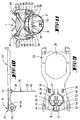
- the pivoting plate 33 which is pivotably attached to the underside of the drag cover T, carries an actuating projection B which is displaceably mounted against the force of a molded-on spring element 47 which is designed in the form of a part-circle section in plan form B is always applied in a direction pointing towards the free end of the swivel plate 33.
- the swivel plate 33 and the actuation projection B provided with the spring element 47 are made in one piece, for which purpose the swivel plate 33 has a recess 49 in the region of the ring spring element 47 which accommodates the spring element 47 and the actuation projection B.
- this carrier section 50 forms a slideway for the actuation projection B when it moves along the guide 48.
- the actuating projection B carries a protruding actuating nose 51, which is oriented approximately perpendicular to the direction of extension thereof and which, in the course of closing the filter chamber 7 by means of the drag cover T, takes the closure element V of the described holding plate 19 of the dust filter bag 16 with it.
- an actuating foot 52 is associated with the actuating projection B in a side-by-side arrangement — related to the direction of movement of the actuating projection B — which are rigidly formed on the swivel plate 33.
- the mounting feet 52 are formed in the respective corner regions of the swivel plate 33 assigned to the actuating projection B on the underside thereof facing away from the actuating projection B. Furthermore, the arrangement is such that the mounting feet 52 are positioned outside the area of the integrated ring spring element 47.
- Each attachment foot 52 has an irregular, triangular plan, essentially with reference to a side view according to FIG. 10.
- a bearing bore is provided for receiving a roller axis 53 of a mounting roller 54 assigned to the mounting foot 52.
- the positioning and diameter of each mounting roller 54 are selected such that an imaginary extension of the top of the swivel plate 33 and one transverse to the longitudinal extent of the pivot plate 33, the actuating projection B in the region of its actuating lug 51, touch the mounting rollers 54.
- the actuating projection B with its actuating nose 51 finds the form-fitting recess 28 of the closure element V on the holding plate side.
- the placement rollers 54 are placed on the lateral support surfaces 55 of the holding plate 19.
- the pivot plate 32 pivots about the hinge 34 counter to the spring force of the spreading spring 36 in the direction of the underside of the drag cover T, which leads to a return displacement of the closure element V to release the suction opening 22.
- the closed position is shown in FIG. 6. It can be seen that the swivel plate 33 is folded against the drag cover T and is aligned essentially parallel to the drag cover T.
- registration protrusions 56 formed on the underside of the drag cover T enter recesses 57 in the rear of the pivot plate 33 with respect to the spring mobility of the actuation protrusion B.
- two registration projections 56 are provided, which move into separate recesses 57.
- the design is such that the recesses 57 are formed in the region of the carrier section 50 of the swivel plate 33.
- the registration protrusions 56 each have a run-up slope 58, which, in the closed state of the system, cause the actuation protrusion B to be positively controlled into a position that releases the spring force of the spring element 47.
- This has the advantageous effect that the spring element 47 is relieved in the open position of the dust filter bag closure, which position corresponds to the normal operating position of the vacuum cleaner, so that the permanent load on the components loaded by the spring element 47 is kept low. As a result, the static forces in the system are kept low when the mechanics are closed.
- the closure element V is displaced via the actuating projection B as a result of the spreading of the drag cover 33 by the spreading spring 36 into a position closing the suction opening 22 of the holding plate 19.
- the ends of the spring leg 39 designed as eyelets 40 slide along the underside of the drag cover T up to the stop-limited swivel end position.
- the run-up slopes 46 in the area of the stops 45 enable a high closing force in the end position, which ensures that the closing element V is brought into the position closing the suction opening 22.
Landscapes
- Engineering & Computer Science (AREA)
- Mechanical Engineering (AREA)
- Filters For Electric Vacuum Cleaners (AREA)
- Sampling And Sample Adjustment (AREA)
Applications Claiming Priority (2)
| Application Number | Priority Date | Filing Date | Title |
|---|---|---|---|
| DE19644897 | 1996-10-29 | ||
| DE19644897A DE19644897A1 (de) | 1996-10-29 | 1996-10-29 | Staubsauger mit einer Kammer zur Aufnahme eines Staubfilterbeutels |
Publications (3)
| Publication Number | Publication Date |
|---|---|
| EP0839493A2 true EP0839493A2 (fr) | 1998-05-06 |
| EP0839493A3 EP0839493A3 (fr) | 1998-12-02 |
| EP0839493B1 EP0839493B1 (fr) | 2003-01-29 |
Family
ID=7810290
Family Applications (1)
| Application Number | Title | Priority Date | Filing Date |
|---|---|---|---|
| EP97114890A Expired - Lifetime EP0839493B1 (fr) | 1996-10-29 | 1997-08-28 | Aspirateur comportant une chambre pour recevoir un sac à poussières |
Country Status (6)
| Country | Link |
|---|---|
| EP (1) | EP0839493B1 (fr) |
| AT (1) | ATE231704T1 (fr) |
| DE (2) | DE19644897A1 (fr) |
| DK (1) | DK0839493T3 (fr) |
| ES (1) | ES2189908T3 (fr) |
| PT (1) | PT839493E (fr) |
Cited By (2)
| Publication number | Priority date | Publication date | Assignee | Title |
|---|---|---|---|---|
| US6564438B1 (en) | 1998-03-03 | 2003-05-20 | Heberlein Fibertechnology, Inc. | Method for air-bubble texturing endless filament yarn, yarn finishing device and its use |
| CN111872907A (zh) * | 2020-07-30 | 2020-11-03 | 吉安职业技术学院 | 组合式机械加工工作台 |
Families Citing this family (1)
| Publication number | Priority date | Publication date | Assignee | Title |
|---|---|---|---|---|
| EP3571971B1 (fr) * | 2018-05-24 | 2023-06-07 | Wolf PVG GmbH & Co. KG | Dispositif de guidage d'un aspirateur doté d'un sac d'aspirateur, procédé de positionnement d'un sac d'aspirateur et plaque de retenue |
Family Cites Families (2)
| Publication number | Priority date | Publication date | Assignee | Title |
|---|---|---|---|---|
| HUT74220A (en) * | 1993-12-03 | 1996-11-28 | Vorwerk Co Interholding | Filter bag for a vacuum cleaner |
| DE19531888B4 (de) * | 1995-06-06 | 2005-02-17 | Vorwerk & Co. Interholding Gmbh | Staubsauger mit einem Staubfilterbeutel |
-
1996
- 1996-10-29 DE DE19644897A patent/DE19644897A1/de not_active Withdrawn
-
1997
- 1997-08-28 EP EP97114890A patent/EP0839493B1/fr not_active Expired - Lifetime
- 1997-08-28 DK DK97114890T patent/DK0839493T3/da active
- 1997-08-28 ES ES97114890T patent/ES2189908T3/es not_active Expired - Lifetime
- 1997-08-28 DE DE59709219T patent/DE59709219D1/de not_active Expired - Fee Related
- 1997-08-28 AT AT97114890T patent/ATE231704T1/de not_active IP Right Cessation
- 1997-08-28 PT PT97114890T patent/PT839493E/pt unknown
Cited By (2)
| Publication number | Priority date | Publication date | Assignee | Title |
|---|---|---|---|---|
| US6564438B1 (en) | 1998-03-03 | 2003-05-20 | Heberlein Fibertechnology, Inc. | Method for air-bubble texturing endless filament yarn, yarn finishing device and its use |
| CN111872907A (zh) * | 2020-07-30 | 2020-11-03 | 吉安职业技术学院 | 组合式机械加工工作台 |
Also Published As
| Publication number | Publication date |
|---|---|
| ATE231704T1 (de) | 2003-02-15 |
| PT839493E (pt) | 2003-06-30 |
| DE59709219D1 (de) | 2003-03-06 |
| EP0839493A3 (fr) | 1998-12-02 |
| DK0839493T3 (da) | 2003-05-26 |
| ES2189908T3 (es) | 2003-07-16 |
| EP0839493B1 (fr) | 2003-01-29 |
| DE19644897A1 (de) | 1998-04-30 |
Similar Documents
| Publication | Publication Date | Title |
|---|---|---|
| EP0313720B1 (fr) | Dispositif à main pour transférer un film d'une feuille porteuse sur un substrat | |
| DE4339298C1 (de) | Filterbeutel für Staubsauger | |
| DE2514719C2 (de) | Einrichtung zum Austeilen und gleichzeitigen Schneiden von aufgerollten Materialstreifen | |
| DE4339297C1 (de) | Filterbeutel für einen Staubsauger | |
| EP0731659B1 (fr) | Sac-filtre a poussiere pour aspirateur | |
| DE69717830T2 (de) | Handapparat zum aufbringen eines klebe- oder beschichtungs- oder farbbands vom trägermaterial, das auf einer vorratsrolle aufgewickelt ist, auf eine oberfläche | |
| DE102008037409B4 (de) | Staubfilterbeutel-Aufnahmekammer für einen Staubsauger und Staubfilterbeutel zur Anordnung in der Staubfilterbeutel-Aufnahmekammer | |
| DE9001473U1 (de) | Handgerät zum Entfernen von Tierexkrementen | |
| DE8816744U1 (de) | Filterbeutel für Elektro-Staubsauger | |
| DE60003211T2 (de) | Spender für aufwischmaterial | |
| DE3030817C2 (de) | Fahrzeugdach mit innerhalb einer Dachöffnung angeordnetem abnehmbaren Deckel | |
| DE4013935C2 (de) | Bandspender | |
| DE29502642U1 (de) | Handgerät zum Übertragen eines Films von einem Trägerband auf ein Substrat | |
| DE2105023B2 (de) | Handgeraet zum auftragen von klebband | |
| EP0839493A2 (fr) | Aspirateur comportant une chambre pour recevoir un sac à poussières | |
| EP0537438A1 (fr) | Classeur pour feuilles mobiles | |
| EP0479001B1 (fr) | Cassette échangeable | |
| EP0207059B1 (fr) | Dispositif de fermeture pour classeur | |
| DE4341248C2 (de) | Staubfilterbeutel für einen Staubsauger | |
| EP0548578A1 (fr) | Guide du rouleau encreur d'une étiqueteuse à main | |
| DE19531888B4 (de) | Staubsauger mit einem Staubfilterbeutel | |
| EP1068828B1 (fr) | Aspirateur | |
| EP1530667B1 (fr) | Dispositif de fermeture pour fenetres, portes ou ouvertures similaires | |
| DE3916343C1 (en) | Retractable pen with spring-loaded flap - has angled sleeve which is closed by flap and has pivoting lug | |
| DE2620688C3 (de) | Vorrichtung zum Umlegen eines Abschlußblattes |
Legal Events
| Date | Code | Title | Description |
|---|---|---|---|
| PUAI | Public reference made under article 153(3) epc to a published international application that has entered the european phase |
Free format text: ORIGINAL CODE: 0009012 |
|
| AK | Designated contracting states |
Kind code of ref document: A2 Designated state(s): AT BE CH DE DK ES FI FR GB GR IE IT LI NL PT SE |
|
| AX | Request for extension of the european patent |
Free format text: AL;LT;LV;RO;SI |
|
| PUAL | Search report despatched |
Free format text: ORIGINAL CODE: 0009013 |
|
| AK | Designated contracting states |
Kind code of ref document: A3 Designated state(s): AT BE CH DE DK ES FI FR GB GR IE IT LI LU MC NL PT SE |
|
| AX | Request for extension of the european patent |
Free format text: AL;LT;LV;RO;SI |
|
| 17P | Request for examination filed |
Effective date: 19990521 |
|
| AKX | Designation fees paid |
Free format text: AT BE CH DE DK ES FI FR GB GR IE IT LI NL PT SE |
|
| 17Q | First examination report despatched |
Effective date: 19990924 |
|
| GRAH | Despatch of communication of intention to grant a patent |
Free format text: ORIGINAL CODE: EPIDOS IGRA |
|
| GRAH | Despatch of communication of intention to grant a patent |
Free format text: ORIGINAL CODE: EPIDOS IGRA |
|
| GRAA | (expected) grant |
Free format text: ORIGINAL CODE: 0009210 |
|
| AK | Designated contracting states |
Designated state(s): AT BE CH DE DK ES FI FR GB GR IE IT LI NL PT SE |
|
| REG | Reference to a national code |
Ref country code: GB Ref legal event code: FG4D Free format text: NOT ENGLISH |
|
| REG | Reference to a national code |
Ref country code: CH Ref legal event code: EP |
|
| REG | Reference to a national code |
Ref country code: CH Ref legal event code: NV Representative=s name: R. A. EGLI & CO. PATENTANWAELTE |
|
| REG | Reference to a national code |
Ref country code: IE Ref legal event code: FG4D Free format text: GERMAN |
|
| REF | Corresponds to: |
Ref document number: 59709219 Country of ref document: DE Date of ref document: 20030306 Kind code of ref document: P |
|
| REG | Reference to a national code |
Ref country code: SE Ref legal event code: TRGR |
|
| REG | Reference to a national code |
Ref country code: GR Ref legal event code: EP Ref document number: 20030401342 Country of ref document: GR |
|
| REG | Reference to a national code |
Ref country code: DK Ref legal event code: T3 |
|
| GBT | Gb: translation of ep patent filed (gb section 77(6)(a)/1977) |
Effective date: 20030519 |
|
| REG | Reference to a national code |
Ref country code: PT Ref legal event code: SC4A Free format text: AVAILABILITY OF NATIONAL TRANSLATION Effective date: 20030416 |
|
| ET | Fr: translation filed | ||
| REG | Reference to a national code |
Ref country code: ES Ref legal event code: FG2A Ref document number: 2189908 Country of ref document: ES Kind code of ref document: T3 |
|
| PGFP | Annual fee paid to national office [announced via postgrant information from national office to epo] |
Ref country code: NL Payment date: 20030805 Year of fee payment: 7 Ref country code: GB Payment date: 20030805 Year of fee payment: 7 Ref country code: DK Payment date: 20030805 Year of fee payment: 7 Ref country code: CH Payment date: 20030805 Year of fee payment: 7 |
|
| PG25 | Lapsed in a contracting state [announced via postgrant information from national office to epo] |
Ref country code: IE Free format text: LAPSE BECAUSE OF NON-PAYMENT OF DUE FEES Effective date: 20030828 Ref country code: FI Free format text: LAPSE BECAUSE OF NON-PAYMENT OF DUE FEES Effective date: 20030828 |
|
| PG25 | Lapsed in a contracting state [announced via postgrant information from national office to epo] |
Ref country code: SE Free format text: LAPSE BECAUSE OF NON-PAYMENT OF DUE FEES Effective date: 20030829 Ref country code: ES Free format text: LAPSE BECAUSE OF NON-PAYMENT OF DUE FEES Effective date: 20030829 |
|
| PGFP | Annual fee paid to national office [announced via postgrant information from national office to epo] |
Ref country code: GR Payment date: 20030829 Year of fee payment: 7 |
|
| PG25 | Lapsed in a contracting state [announced via postgrant information from national office to epo] |
Ref country code: BE Free format text: LAPSE BECAUSE OF NON-PAYMENT OF DUE FEES Effective date: 20030831 |
|
| PLBE | No opposition filed within time limit |
Free format text: ORIGINAL CODE: 0009261 |
|
| 26N | No opposition filed |
Effective date: 20031030 |
|
| BERE | Be: lapsed |
Owner name: *VORWERK & CO. INTERHOLDING G.M.B.H. Effective date: 20030831 |
|
| EUG | Se: european patent has lapsed | ||
| REG | Reference to a national code |
Ref country code: IE Ref legal event code: MM4A |
|
| PGFP | Annual fee paid to national office [announced via postgrant information from national office to epo] |
Ref country code: PT Payment date: 20040824 Year of fee payment: 8 |
|
| PG25 | Lapsed in a contracting state [announced via postgrant information from national office to epo] |
Ref country code: GB Free format text: LAPSE BECAUSE OF NON-PAYMENT OF DUE FEES Effective date: 20040828 |
|
| PG25 | Lapsed in a contracting state [announced via postgrant information from national office to epo] |
Ref country code: LI Free format text: LAPSE BECAUSE OF NON-PAYMENT OF DUE FEES Effective date: 20040831 Ref country code: DK Free format text: LAPSE BECAUSE OF NON-PAYMENT OF DUE FEES Effective date: 20040831 Ref country code: CH Free format text: LAPSE BECAUSE OF NON-PAYMENT OF DUE FEES Effective date: 20040831 |
|
| REG | Reference to a national code |
Ref country code: ES Ref legal event code: FD2A Effective date: 20030829 |
|
| PG25 | Lapsed in a contracting state [announced via postgrant information from national office to epo] |
Ref country code: NL Free format text: LAPSE BECAUSE OF NON-PAYMENT OF DUE FEES Effective date: 20050301 |
|
| PG25 | Lapsed in a contracting state [announced via postgrant information from national office to epo] |
Ref country code: GR Free format text: LAPSE BECAUSE OF NON-PAYMENT OF DUE FEES Effective date: 20050303 |
|
| REG | Reference to a national code |
Ref country code: CH Ref legal event code: PL |
|
| GBPC | Gb: european patent ceased through non-payment of renewal fee |
Effective date: 20040828 |
|
| NLV4 | Nl: lapsed or anulled due to non-payment of the annual fee |
Effective date: 20050301 |
|
| REG | Reference to a national code |
Ref country code: DK Ref legal event code: EBP |
|
| PG25 | Lapsed in a contracting state [announced via postgrant information from national office to epo] |
Ref country code: PT Free format text: LAPSE BECAUSE OF NON-PAYMENT OF DUE FEES Effective date: 20060228 |
|
| PGFP | Annual fee paid to national office [announced via postgrant information from national office to epo] |
Ref country code: DE Payment date: 20080812 Year of fee payment: 12 |
|
| PGFP | Annual fee paid to national office [announced via postgrant information from national office to epo] |
Ref country code: IT Payment date: 20080827 Year of fee payment: 12 Ref country code: FR Payment date: 20080812 Year of fee payment: 12 Ref country code: AT Payment date: 20080813 Year of fee payment: 12 |
|
| REG | Reference to a national code |
Ref country code: FR Ref legal event code: ST Effective date: 20100430 |
|
| PG25 | Lapsed in a contracting state [announced via postgrant information from national office to epo] |
Ref country code: AT Free format text: LAPSE BECAUSE OF NON-PAYMENT OF DUE FEES Effective date: 20090828 |
|
| PG25 | Lapsed in a contracting state [announced via postgrant information from national office to epo] |
Ref country code: FR Free format text: LAPSE BECAUSE OF NON-PAYMENT OF DUE FEES Effective date: 20090831 Ref country code: DE Free format text: LAPSE BECAUSE OF NON-PAYMENT OF DUE FEES Effective date: 20100302 |
|
| PG25 | Lapsed in a contracting state [announced via postgrant information from national office to epo] |
Ref country code: IT Free format text: LAPSE BECAUSE OF NON-PAYMENT OF DUE FEES Effective date: 20090828 |