EP0840148B1 - Coupleur de fibres optiques et méthode pour sa fabrication - Google Patents
Coupleur de fibres optiques et méthode pour sa fabrication Download PDFInfo
- Publication number
- EP0840148B1 EP0840148B1 EP98100271A EP98100271A EP0840148B1 EP 0840148 B1 EP0840148 B1 EP 0840148B1 EP 98100271 A EP98100271 A EP 98100271A EP 98100271 A EP98100271 A EP 98100271A EP 0840148 B1 EP0840148 B1 EP 0840148B1
- Authority
- EP
- European Patent Office
- Prior art keywords
- fused
- optical fiber
- fiber coupler
- optical
- coupler
- Prior art date
- Legal status (The legal status is an assumption and is not a legal conclusion. Google has not performed a legal analysis and makes no representation as to the accuracy of the status listed.)
- Expired - Lifetime
Links
Images

Classifications
-
- G—PHYSICS
- G02—OPTICS
- G02B—OPTICAL ELEMENTS, SYSTEMS OR APPARATUS
- G02B6/00—Light guides; Structural details of arrangements comprising light guides and other optical elements, e.g. couplings
- G02B6/24—Coupling light guides
- G02B6/26—Optical coupling means
- G02B6/28—Optical coupling means having data bus means, i.e. plural waveguides interconnected and providing an inherently bidirectional system by mixing and splitting signals
- G02B6/293—Optical coupling means having data bus means, i.e. plural waveguides interconnected and providing an inherently bidirectional system by mixing and splitting signals with wavelength selective means
- G02B6/29331—Optical coupling means having data bus means, i.e. plural waveguides interconnected and providing an inherently bidirectional system by mixing and splitting signals with wavelength selective means operating by evanescent wave coupling
- G02B6/29332—Wavelength selective couplers, i.e. based on evanescent coupling between light guides, e.g. fused fibre couplers with transverse coupling between fibres having different propagation constant wavelength dependency
-
- G—PHYSICS
- G02—OPTICS
- G02B—OPTICAL ELEMENTS, SYSTEMS OR APPARATUS
- G02B6/00—Light guides; Structural details of arrangements comprising light guides and other optical elements, e.g. couplings
- G02B6/24—Coupling light guides
- G02B6/255—Splicing of light guides, e.g. by fusion or bonding
- G02B6/2552—Splicing of light guides, e.g. by fusion or bonding reshaping or reforming of light guides for coupling using thermal heating, e.g. tapering, forming of a lens on light guide ends
-
- G—PHYSICS
- G02—OPTICS
- G02B—OPTICAL ELEMENTS, SYSTEMS OR APPARATUS
- G02B6/00—Light guides; Structural details of arrangements comprising light guides and other optical elements, e.g. couplings
- G02B6/24—Coupling light guides
- G02B6/26—Optical coupling means
- G02B6/28—Optical coupling means having data bus means, i.e. plural waveguides interconnected and providing an inherently bidirectional system by mixing and splitting signals
- G02B6/2804—Optical coupling means having data bus means, i.e. plural waveguides interconnected and providing an inherently bidirectional system by mixing and splitting signals forming multipart couplers without wavelength selective elements, e.g. "T" couplers, star couplers
- G02B6/2821—Optical coupling means having data bus means, i.e. plural waveguides interconnected and providing an inherently bidirectional system by mixing and splitting signals forming multipart couplers without wavelength selective elements, e.g. "T" couplers, star couplers using lateral coupling between contiguous fibres to split or combine optical signals
- G02B6/2835—Optical coupling means having data bus means, i.e. plural waveguides interconnected and providing an inherently bidirectional system by mixing and splitting signals forming multipart couplers without wavelength selective elements, e.g. "T" couplers, star couplers using lateral coupling between contiguous fibres to split or combine optical signals formed or shaped by thermal treatment, e.g. couplers
-
- G—PHYSICS
- G02—OPTICS
- G02B—OPTICAL ELEMENTS, SYSTEMS OR APPARATUS
- G02B6/00—Light guides; Structural details of arrangements comprising light guides and other optical elements, e.g. couplings
- G02B6/24—Coupling light guides
- G02B6/26—Optical coupling means
- G02B6/28—Optical coupling means having data bus means, i.e. plural waveguides interconnected and providing an inherently bidirectional system by mixing and splitting signals
- G02B6/2804—Optical coupling means having data bus means, i.e. plural waveguides interconnected and providing an inherently bidirectional system by mixing and splitting signals forming multipart couplers without wavelength selective elements, e.g. "T" couplers, star couplers
- G02B2006/2865—Optical coupling means having data bus means, i.e. plural waveguides interconnected and providing an inherently bidirectional system by mixing and splitting signals forming multipart couplers without wavelength selective elements, e.g. "T" couplers, star couplers couplers of the 3x3 type
Definitions
- the present invention concerns couplers for optical fibers.
- couplers for optical fibers For coupling optical signals and for causing optical signals to branch over one or more optical fibers, one such coupler known in the art is referred to as the fused-elongated type coupler.
- FIG. 1 one example of a conventional fused-elongated type optical fiber coupler is shown.
- the optical fiber coupler 1 shown in the drawing is formed by aligning a section of each of two component optical fibers 2, mutually thermally fusing the aligned sections thereby forming a fused section, and then elongating or drawing out the heated fused section to form a fused-elongated region 3.
- each component optical fiber 2 is reduced as is the core of the component optical fibers 2.
- a proportionately greater fraction of the energy of the light propagated therein leaks through the cladding which surrounds the core.
- the distance between the cores of adjacent optical fibers 2 is reduced, and due to this fact, the coupling between the propagated modes of the individual fibers becomes extremely great. In this way, the optical signal incident on one fiber 2 becomes split and is thus emitted at ports of both optical fibers 2. In the same way, separate optical signals incident on both component optical fibers 2 become combined.
- the conventional optical fiber coupler 1 With the conventional optical fiber coupler 1 described above, it is known that light incident on one optical fiber becomes proportioned over one or both optical fibers (referred to as coupling ratio) based on the wavelength of the incident light.
- light incident on port A (or port B) of the optical fiber coupler 1 shown in Fig. 1 may be emitted by port C or port D, depending on the wavelength of the incident light.
- the graph of Fig. 2 which shows the percentage of light incident on port A of optical fiber coupler 1 that is emitted by port D as a function of the wavelength of the light incident on port A
- the relationship between coupling ratio and wavelength is a sinusoidal function.
- Optical fiber couplers do exist in which the fluctuation of coupling ratio as a function of wavelength is relatively flat. These optical fiber couplers having weak wavelength dependance for coupling ratio are known as wide wavelength range optical fiber couplers, an example of which is shown in Fig. 3.
- the conventional wide wavelength range optical fiber coupler 4 shown in Fig. 3 includes an optical fiber 5, a portion of which has undergone a preliminary elongation, and a conventional optical fiber 2.
- the initially elongated region of optical fiber 5 and a section of optical fiber 2 are aligned side by side and mutually thermally fused to form a fused section.
- the fused section thus formed is then elongated or drawn out to form a fused-elongated region 6.
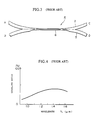
- Fig. 4 shows for optical fiber coupler 4, the percentage of light incident on port A that is emitted by port D as a function of the wavelength of the light incident on port A.
- Fig. 4 shows, for the conventional wide wavelength range optical fiber coupler 4, while relatively level compared with that of conventional optical fiber coupler 1, the coupling ratio as a function of wavelength does demonstrate a hump and thus, the conventional wide wavelength range optical fiber coupler 4 does not achieve truly flat, wavelength independent characteristics.
- the reason for this is thought to be that for the conventional wide wavelength range optical fiber coupler 4, even after elongation and reduction of the respective fibers' diameters, the central axes of each component optical fiber 2, 5 in the fused-elongated region 6 lie in the same plane.
- the modes which participate in coupling are thought to be limited to the fundamental modes of each core of each component optical fiber 2, 5. Based on light transmission coupling theory, it is believed that for mode coupling between only two modes, that the mode coupling waveform is such that perfectly flat wavelength characteristics cannot be attained.
- the present invention provides an optical fibre coupler comprising at least two constituent optical fibres that extend alongside one another and that have been twisted together whereby the coupler is formed by fusing together adjacent lateral portions and then elongating the fused section to form a fused-elongated region, characterised in that the fibres have an "SZ" twist which forms perturbations in the fused-elongated region so that the mode coupling state between said at least two constituent optical fibres in said fused-elongated region is a multiple mode coupling state.
- the present invention provides a method of manufacturing an optical fibre coupler comprising fusing together adjacent lateral portions of at least two constituent optical fibres that extend alongside one another and that have been twisted together and then elongating the fused section to form a fused-elongated region, characterised in that the fibres have an "SZ" twist which forms perturbations in the fused-elongate region so that the mode coupling state between said at least two constituent optical fibres in said fused-elongate region is a multiple mode coupling state.
- Fig. 1 is a side view of an example of a conventional optical fiber coupler.
- Fig. 2 is a graph illustrating the wavelength dependency properties of the coupling ratio for the conventional optical fiber coupler shown in Fig. 1.
- Fig. 3 is a side view of an example of a conventional wide bandpass optical fiber coupler.
- Fig. 4 is a graph illustrating the wavelength dependency properties of the coupling ratio for the conventional wide bandpass optical fiber coupler shown in Fig. 3.
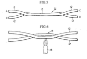
- Fig. 5 is a side view of the optical fiber coupler of a first preferred embodiment of the present invention.
- Fig. 6 is an explanatory side view for one example of a manufacturing method for the optical fiber shown in Fig. 5.
- optical fiber coupler 11 (hereafter referred to as optical fiber coupler) of the present embodiment as shown in Fig. 5 consists of a fused-elongated region 13 with a twisting deformation formed from a section of each of two strands of a component single mode optical fiber 12 (hereafter referred to as optical fiber).
- the twisting deformation of the above mentioned fused-elongated region 13 is preferably formed by first imposing a twisting on a section of each component optical fiber 12 prior to forming the fused-elongated region 13, then mutually thermally fusing the twisted sections, and finally drawing out the twisted, thermally fused section.
- the "SZ" twist shown in Fig. 6 has been found to be effective. With this kind of SZ twist, even though a twist is present, each component optical fiber 12 joins and leaves the fused-elongated region 13 on the same side, thus providing more convenient application. Further, with this kind of twisted fused-elongated region 13, very low optical losses and a coupling ratio which is relatively wavelength independent can be easily achieved.
- each of two component optical fibers 12 are aligned side by side, after which the SZ twist shown in the drawing is imparted on the aligned portion of the component optical fibers 12, thereby forming a twisted region 14. While each end of the twisted region 14 is held in a clamp (not shown in the drawing), the twisted region 14 is fused using a hydrogen-oxygen burner 15, after which the above mentioned clamps are moved in opposite directions, thereby stretching and elongating the fused region and forming the fused-elongated region 13. In this way, the optical fiber coupler 11 shown in Fig. 5 can be fabricated.
- optical fiber coupler 11 With this kind of optical fiber coupler 11, by imparting a twisting deformation in the fused-elongated region 13, in addition to the fundamental modes of each component optical fiber 12, additional modes are caused to be formed. Through the participation of these additional modes with the coupling of the fundamental modes, the mode coupling state becomes a multiple mode coupling state, whereby the strength of coupling at predetermined wavelengths can be controlled, and by which means it is possible to create an optical fiber coupler 11 of which the coupling ratio is largely wavelength independent and hence constant over a wide range of wavelengths.
- the primary coating layer was removed from each fiber over a length of 40 mm, thereby exposing the cladding.
- the exposed sections from the two optical fibers were aligned side by side so that the exposed portions were in contact.
- An SZ twist was then imposed one time over the section of contacting exposed cores, with both ends of the exposed sections being fixed in a respective clamp.
- the exposed sections between the two clamps were heated with a hydrogen-oxygen burner, whereby a central section of the exposed cores of 20 mm length was mutually fused, while at the same time, the clamps were drawn apart, thereby forming a fused-elongated region having a length of 15 mm and an external diameter of 70 ⁇ m which is the same as the optical fiber coupler 11 shown in Fig. 5.
- the wavelength dependency characteristics of the coupling ratio (the coupling ratio from port A to port C) were measured.
- the optical fiber coupler 11 produced by the above described method demonstrated a variation in the strength of the coupling ratio with wavelength that was barely detectable, and thus possessed exceedingly flat wavelength dependency characteristics.
- optical fiber coupler of the present invention includes all forms encompassed by the appended claims.
Landscapes
- Physics & Mathematics (AREA)
- General Physics & Mathematics (AREA)
- Optics & Photonics (AREA)
- Engineering & Computer Science (AREA)
- Plasma & Fusion (AREA)
- Optical Couplings Of Light Guides (AREA)
- Optical Integrated Circuits (AREA)
Claims (2)
- Coupleur de fibres optiques (11) comprenant au moins deux fibres optiques constitutantes (12) qui s'étendent l'une à côté de l'autre selon la direction longitudinale et qui ont été tordues ensemble, et ainsi le coupleur est formé en thermo-soudant l'une à l'autre les parties latérales adjacentes puis en allongeant la section soudée de façon à former une région à soudure allongée (13), caractérisé en ce que les fibres comportent une torsion "SZ" formant des perturbations dans la région à soudure allongée (13), de sorte que l'état de couplage de modes entre lesdites au moins deux fibres optiques constituantes (12) dans ladite région à soudure allongée (13) est un état de couplage de modes multiples.
- Procédé de fabrication d'un coupleur de fibres optiques comprenant les étapes consistant à thermo-souder l'une à l'autre les parties latérales adjacentes d'au moins deux fibres optiques constituantes (12) qui s'étendent l'une à côté de l'autre selon la direction longitudinale et qui ont été tordues ensemble, puis à allonger la section soudée de façon à former une région à soudure allongée (13), caractérisé en ce que les fibres comportent une torsion "SZ" formant des perturbations dans la région à soudure allongée (13) de sorte que l'état de couplage de modes entre lesdites au moins deux fibres optiques constituantes (12) dans ladite région à soudure allongée (13) est un état de couplage de modes multiples.
Applications Claiming Priority (7)
| Application Number | Priority Date | Filing Date | Title |
|---|---|---|---|
| JP15996989A JPH0324506A (ja) | 1989-06-22 | 1989-06-22 | 広波長域形光ファイバカプラ |
| JP15996989 | 1989-06-22 | ||
| JP159969/89 | 1989-06-22 | ||
| JP191908/89 | 1989-07-25 | ||
| JP19190889 | 1989-07-25 | ||
| JP19190889A JPH0355505A (ja) | 1989-07-25 | 1989-07-25 | 光ファイバカプラおよびその製造方法 |
| EP90306839A EP0404587B1 (fr) | 1989-06-22 | 1990-06-22 | Coupleur à fibre optique et sa méthode de fabrication |
Related Parent Applications (2)
| Application Number | Title | Priority Date | Filing Date |
|---|---|---|---|
| EP90306839A Division EP0404587B1 (fr) | 1989-06-22 | 1990-06-22 | Coupleur à fibre optique et sa méthode de fabrication |
| EP90306839.3 Division | 1990-06-22 |
Publications (3)
| Publication Number | Publication Date |
|---|---|
| EP0840148A2 EP0840148A2 (fr) | 1998-05-06 |
| EP0840148A3 EP0840148A3 (fr) | 1998-11-25 |
| EP0840148B1 true EP0840148B1 (fr) | 2001-08-29 |
Family
ID=26486606
Family Applications (2)
| Application Number | Title | Priority Date | Filing Date |
|---|---|---|---|
| EP98100271A Expired - Lifetime EP0840148B1 (fr) | 1989-06-22 | 1990-06-22 | Coupleur de fibres optiques et méthode pour sa fabrication |
| EP90306839A Expired - Lifetime EP0404587B1 (fr) | 1989-06-22 | 1990-06-22 | Coupleur à fibre optique et sa méthode de fabrication |
Family Applications After (1)
| Application Number | Title | Priority Date | Filing Date |
|---|---|---|---|
| EP90306839A Expired - Lifetime EP0404587B1 (fr) | 1989-06-22 | 1990-06-22 | Coupleur à fibre optique et sa méthode de fabrication |
Country Status (3)
| Country | Link |
|---|---|
| US (1) | US5058979A (fr) |
| EP (2) | EP0840148B1 (fr) |
| DE (2) | DE69033788T2 (fr) |
Families Citing this family (24)
| Publication number | Priority date | Publication date | Assignee | Title |
|---|---|---|---|---|
| US5146519A (en) * | 1990-08-28 | 1992-09-08 | Corning Incorporated | Rotary variable optical tap |
| DE4109982A1 (de) * | 1991-03-27 | 1992-10-01 | Standard Elektrik Lorenz Ag | Verfahren zur herstellung eines optischen verschmelzkopplers |
| EP0549332B1 (fr) * | 1991-12-24 | 1999-03-17 | The Whitaker Corporation | Dispositif de couplage optique |
| EP0694173A1 (fr) * | 1992-01-02 | 1996-01-31 | Adc Telecommunications, Inc. | Attenuateur a fibres optiques superposees et fondues |
| US5319733A (en) * | 1992-01-02 | 1994-06-07 | Adc Telecommunications, Inc. | Variable fiber optical attenuator |
| US6148129A (en) * | 1993-01-15 | 2000-11-14 | E-Tek Dynamics, Inc. | Broad bandwidth, single mode fiber optic coupler and method of manufacture |
| GB2280968B (en) * | 1993-08-12 | 1996-07-31 | Northern Telecom Ltd | Chirped optical fibre filter |
| CA2123757C (fr) * | 1994-05-17 | 2002-06-25 | Francois Gonthier | Methode de fabrication de coupleurs de guide de lumiere a faible sensibilite a la longueur d'onde et coupleurs fabriques selon cette methode |
| US5411566A (en) * | 1994-06-08 | 1995-05-02 | At&T Corp. | Optical fiber spatial mode converter using periodic core deformation |
| FR2725529B1 (fr) * | 1994-10-11 | 1996-11-22 | Alcatel Nv | Coupleur optique selectif en longueur d'onde |
| FR2725528B1 (fr) * | 1994-10-11 | 1996-11-22 | Alcatel Nv | Ligne a retard optique selectif en longueur d'onde |
| US5652819A (en) * | 1995-08-09 | 1997-07-29 | The United States Of America As Represented By The Secretary Of The Navy | Method for tuning fiber optic couplers and multiplexers |
| US5694512A (en) * | 1996-07-09 | 1997-12-02 | Framatome Connectors Canada Inc. | Compact tunable wavelength independent all-fiber optical attenuator and method of making same |
| WO1998013711A2 (fr) * | 1996-09-24 | 1998-04-02 | Cary Bloom | Appareil et procede de chauffage et de deformation controles d'une fibre optique |
| US6363190B1 (en) * | 2000-02-11 | 2002-03-26 | New Focus, Inc. | Polarization insensitive fused fiber coupler method and apparatus |
| US20070066076A1 (en) * | 2005-09-19 | 2007-03-22 | Bailey Joel B | Substrate processing method and apparatus using a combustion flame |
| US6928841B2 (en) * | 2002-05-10 | 2005-08-16 | Furukawa Electric North America Inc | Optical fiber preform manufacture using improved VAD |
| JP3974106B2 (ja) * | 2003-12-09 | 2007-09-12 | 大崎電気工業株式会社 | 広帯域光ファイバカプラおよびその製造方法並びにその製造装置 |
| US7896218B2 (en) | 2007-06-28 | 2011-03-01 | Western Digital Technologies, Inc. | Apparatus and method for conductive metal ball bonding with electrostatic discharge detection |
| MX2016001654A (es) | 2013-09-09 | 2016-05-02 | Halliburton Energy Services Inc | Activacion de composiciones de cemento con retardo de fraguado mediante el intercambio de retardante. |
| CN103792620B (zh) * | 2014-02-21 | 2016-01-06 | 嘉隆科技(深圳)有限公司 | 一种抗弯曲光纤耦合器及其制造方法 |
| CN109031531A (zh) * | 2018-08-06 | 2018-12-18 | 上海大学 | 一种具有波分复用功能的模式耦合器及其制备方法 |
| CN117170023B (zh) * | 2022-05-25 | 2025-11-21 | 五邑大学 | 一种高抗性的光纤耦合结构、光纤耦合器及其制备方法 |
| CN119395818B (zh) * | 2025-01-06 | 2025-05-23 | 四川思创激光科技有限公司 | 一种单臂侧贴光纤合束器的制作方法 |
Family Cites Families (11)
| Publication number | Priority date | Publication date | Assignee | Title |
|---|---|---|---|---|
| CA1123642A (fr) * | 1979-07-04 | 1982-05-18 | Alexander W. Lightstone | Connecteur multimode pour fibres optiques |
| US4586784A (en) * | 1983-06-10 | 1986-05-06 | Canadian Patents & Dev. Limited | Modal-insensitive biconical taper couplers |
| AU569803B2 (en) * | 1984-09-06 | 1988-02-18 | Hitachi Limited | Optical fibre star coupler |
| GB8519183D0 (en) * | 1985-07-30 | 1985-09-04 | British Telecomm | Optical fused couplers |
| EP0219096A3 (fr) * | 1985-10-16 | 1989-08-16 | Hitachi, Ltd. | Coupleur étoile à fibre optique et son procédé de fabrication |
| US4746185A (en) * | 1986-06-23 | 1988-05-24 | Shahidi Hamedani Ferrydon | Optical fibre couplers |
| JPH0827418B2 (ja) * | 1987-02-18 | 1996-03-21 | 住友電気工業株式会社 | 分岐用光フアイバケ−ブル |
| US4869570A (en) * | 1987-02-21 | 1989-09-26 | Nippon Telegraph And Telephone Corporation | Fiber coupler and method and apparatus for manufacturing the same |
| US4763272A (en) * | 1987-03-29 | 1988-08-09 | The United States Of America As Represented By The Secretary Of The Navy | Automated and computer controlled precision method of fused elongated optical fiber coupler fabrication |
| JPS63244010A (ja) * | 1987-03-31 | 1988-10-11 | Sumitomo Electric Ind Ltd | 余長付光フアイバケ−ブルの製造方法 |
| GB2207254B (en) * | 1987-07-11 | 1991-03-13 | Stc Plc | Glass clad optical fibre directional couplers. |
-
1990
- 1990-06-21 US US03/242,469 patent/US5058979A/en not_active Expired - Lifetime
- 1990-06-22 EP EP98100271A patent/EP0840148B1/fr not_active Expired - Lifetime
- 1990-06-22 DE DE69033788T patent/DE69033788T2/de not_active Expired - Fee Related
- 1990-06-22 DE DE69032573T patent/DE69032573T2/de not_active Expired - Fee Related
- 1990-06-22 EP EP90306839A patent/EP0404587B1/fr not_active Expired - Lifetime
Also Published As
| Publication number | Publication date |
|---|---|
| DE69032573T2 (de) | 1999-04-08 |
| DE69033788T2 (de) | 2002-05-02 |
| EP0840148A2 (fr) | 1998-05-06 |
| US5058979A (en) | 1991-10-22 |
| EP0404587A3 (fr) | 1992-01-08 |
| DE69033788D1 (de) | 2001-10-04 |
| DE69032573D1 (de) | 1998-09-24 |
| EP0404587A2 (fr) | 1990-12-27 |
| EP0404587B1 (fr) | 1998-08-19 |
| EP0840148A3 (fr) | 1998-11-25 |
Similar Documents
| Publication | Publication Date | Title |
|---|---|---|
| EP0840148B1 (fr) | Coupleur de fibres optiques et méthode pour sa fabrication | |
| US4315666A (en) | Coupled communications fibers | |
| US6078716A (en) | Thermally expanded multiple core fiber | |
| US5553179A (en) | Varied insertion loss fiber optic coupling and method of making same | |
| CA1114661A (fr) | Coupleurs en etoile a faible perte pour systeme a fibres optiques | |
| US4900114A (en) | Technique for reducing fibre joint loss | |
| JPH03182704A (ja) | 受動光部品およびその製造方法 | |
| EP0749025B1 (fr) | Procédé de fabrication d'un coupleur à fibre optique | |
| EP0610973B1 (fr) | Coupleur à fibre optique | |
| KR100786617B1 (ko) | 편파 유지 광파이버 커플러의 제조 방법 | |
| US5644666A (en) | Broadband optical fiber coupler and method of making | |
| JPS60154215A (ja) | フアイバ形方向性結合器 | |
| JPH07253518A (ja) | スターカプラの製造方法とスターカプラ | |
| JPS63129307A (ja) | スタ−カプラ及びその製造法 | |
| JP3101958B2 (ja) | 広帯域カップラおよびその製造方法 | |
| JP2805533B2 (ja) | ファイバ融着型光分岐結合器 | |
| JP2879367B2 (ja) | 光分岐結合器及びその製造方法 | |
| US20020159704A1 (en) | Modified PM tap couplers | |
| CA1105706A (fr) | Mode de fabrication de coupleur d'acces de fibres optiques | |
| AU597178B2 (en) | Asymmetric fibre optic couplers and fabrication thereof | |
| JPH02123308A (ja) | 光ファイバカプラの製造方法 | |
| JPH0193707A (ja) | 光ファイバカプラ | |
| JP2958179B2 (ja) | 光ファイバカプラ及びその製造方法 | |
| JPH0667057A (ja) | 偏波面保存光ファイバカプラ | |
| JP2000206361A (ja) | 光ファイバ型多分岐カプラ―及びその製造方法 |
Legal Events
| Date | Code | Title | Description |
|---|---|---|---|
| PUAI | Public reference made under article 153(3) epc to a published international application that has entered the european phase |
Free format text: ORIGINAL CODE: 0009012 |
|
| 17P | Request for examination filed |
Effective date: 19980129 |
|
| AC | Divisional application: reference to earlier application |
Ref document number: 404587 Country of ref document: EP |
|
| AK | Designated contracting states |
Kind code of ref document: A2 Designated state(s): DE FR GB |
|
| RIN1 | Information on inventor provided before grant (corrected) |
Inventor name: SUZUKI, FUMIO Inventor name: KAWAKAMI, NOBORU Inventor name: YAMAUCHI, RYOZO |
|
| PUAL | Search report despatched |
Free format text: ORIGINAL CODE: 0009013 |
|
| AK | Designated contracting states |
Kind code of ref document: A3 Designated state(s): DE FR GB |
|
| GRAG | Despatch of communication of intention to grant |
Free format text: ORIGINAL CODE: EPIDOS AGRA |
|
| 17Q | First examination report despatched |
Effective date: 20001116 |
|
| GRAG | Despatch of communication of intention to grant |
Free format text: ORIGINAL CODE: EPIDOS AGRA |
|
| GRAH | Despatch of communication of intention to grant a patent |
Free format text: ORIGINAL CODE: EPIDOS IGRA |
|
| GRAH | Despatch of communication of intention to grant a patent |
Free format text: ORIGINAL CODE: EPIDOS IGRA |
|
| GRAA | (expected) grant |
Free format text: ORIGINAL CODE: 0009210 |
|
| AC | Divisional application: reference to earlier application |
Ref document number: 404587 Country of ref document: EP |
|
| AK | Designated contracting states |
Kind code of ref document: B1 Designated state(s): DE FR GB |
|
| REF | Corresponds to: |
Ref document number: 69033788 Country of ref document: DE Date of ref document: 20011004 |
|
| ET | Fr: translation filed | ||
| REG | Reference to a national code |
Ref country code: GB Ref legal event code: IF02 |
|
| PGFP | Annual fee paid to national office [announced via postgrant information from national office to epo] |
Ref country code: FR Payment date: 20020610 Year of fee payment: 13 |
|
| PGFP | Annual fee paid to national office [announced via postgrant information from national office to epo] |
Ref country code: GB Payment date: 20020619 Year of fee payment: 13 |
|
| PGFP | Annual fee paid to national office [announced via postgrant information from national office to epo] |
Ref country code: DE Payment date: 20020626 Year of fee payment: 13 |
|
| PLBE | No opposition filed within time limit |
Free format text: ORIGINAL CODE: 0009261 |
|
| STAA | Information on the status of an ep patent application or granted ep patent |
Free format text: STATUS: NO OPPOSITION FILED WITHIN TIME LIMIT |
|
| 26N | No opposition filed | ||
| PG25 | Lapsed in a contracting state [announced via postgrant information from national office to epo] |
Ref country code: GB Free format text: LAPSE BECAUSE OF NON-PAYMENT OF DUE FEES Effective date: 20030622 |
|
| PG25 | Lapsed in a contracting state [announced via postgrant information from national office to epo] |
Ref country code: DE Free format text: LAPSE BECAUSE OF NON-PAYMENT OF DUE FEES Effective date: 20040101 |
|
| GBPC | Gb: european patent ceased through non-payment of renewal fee |
Effective date: 20030622 |
|
| PG25 | Lapsed in a contracting state [announced via postgrant information from national office to epo] |
Ref country code: FR Free format text: LAPSE BECAUSE OF NON-PAYMENT OF DUE FEES Effective date: 20040227 |
|
| REG | Reference to a national code |
Ref country code: FR Ref legal event code: ST |