EP0840451A1 - Circuit générateur pour générer des signaux sans chevauchement - Google Patents
Circuit générateur pour générer des signaux sans chevauchement Download PDFInfo
- Publication number
- EP0840451A1 EP0840451A1 EP96830554A EP96830554A EP0840451A1 EP 0840451 A1 EP0840451 A1 EP 0840451A1 EP 96830554 A EP96830554 A EP 96830554A EP 96830554 A EP96830554 A EP 96830554A EP 0840451 A1 EP0840451 A1 EP 0840451A1
- Authority
- EP
- European Patent Office
- Prior art keywords
- output
- circuit
- input terminal
- generating circuit
- output terminal
- Prior art date
- Legal status (The legal status is an assumption and is not a legal conclusion. Google has not performed a legal analysis and makes no representation as to the accuracy of the status listed.)
- Withdrawn
Links
- 239000003990 capacitor Substances 0.000 claims description 22
- 230000003111 delayed effect Effects 0.000 description 7
- 230000001419 dependent effect Effects 0.000 description 3
- 239000000243 solution Substances 0.000 description 2
- 238000010586 diagram Methods 0.000 description 1
- 238000007599 discharging Methods 0.000 description 1
- 238000002347 injection Methods 0.000 description 1
- 239000007924 injection Substances 0.000 description 1
- 230000000630 rising effect Effects 0.000 description 1
- 238000004088 simulation Methods 0.000 description 1
Images


Classifications
-
- H—ELECTRICITY
- H03—ELECTRONIC CIRCUITRY
- H03K—PULSE TECHNIQUE
- H03K5/00—Manipulating of pulses not covered by one of the other main groups of this subclass
- H03K5/15—Arrangements in which pulses are delivered at different times at several outputs, i.e. pulse distributors
- H03K5/151—Arrangements in which pulses are delivered at different times at several outputs, i.e. pulse distributors with two complementary outputs
- H03K5/1515—Arrangements in which pulses are delivered at different times at several outputs, i.e. pulse distributors with two complementary outputs non-overlapping
Definitions
- This invention relates to a circuit generating non-overlapped digital signals, for integrated devices of the MOS type.
- switched capacitor devices require that digital signals be generated which never are at a high logic level simultaneously, if the device includes N-channel MOS transistors, or simultaneously at a low logic level, if the device includes P-channel MOS transistors, as shown in Figure 1.
- Figure 2 shows an integrator device INT with loss-switched capacitors, which includes first SW1 and second SW2 switches connected to each other through a first circuit node A, and third SW3 and fourth SW4 switches connected to each other through a second circuit node B.
- the integrator device INT further includes a capacitor C connected between the first A and the second B circuit node.
- the switches SW1, SW2, SW3 and SW4 are transistors of the MOS type which are driven by opposed digital signals P1 and P2 non-overlapping each other.
- the second circuit node B is alternatively grounded when the third switch SW3 is closed, or is at the output voltage Vout when the fourth switch SW4 is closed.
- the switches SW3 and SW4 are driven by opposed digital signal P1D and P2D which do not overlap each other and are delayed from the signals P1 and P2, as shown in Figure 3.
- This prior solution provides for the use of a non-overlapped digital signal generating device 1 which comprises first 2 and second 3 logic gates, respectively of the NAND and NOR type, each having a first input driven by a digital clock signal CKL and a second input controlled by a delay circuit 4.
- This circuit having an input driven by the same clock signal CKL, effectively outputs a digital signal CKLrit which is delayed from the clock signal CKL.
- the delay circuit 4 includes a first inverter 5, of a highly resistive type, which has an output connected to ground through a capacitor Crp.
- the output of the first inverter 5 is also connected to an input of a second inverter 6 having an output connected to the second inputs of the logic gates 2 and 3.
- the device 1 operates as explained herein below.
- the charging and discharging of the capacitor Crp causes the rising and falling edges of the clock signal CKL to be presented to the second inverter 6 with a delay which depends on the RC constant of the system.
- the second inverter 6 will produce at its output the signal CKLrit, identical with the signal CKL but delayed a given time period therefrom.
- the device 1 is enabled to output opposed digital signals F1A and F2A which do not overlap each other, as well as opposed and non-overlapped digital signals F1 and F2 which are delayed from the signals F1A and F2A.
- the device 1 is also enabled to generate signals F1A*, F2A*, F1* and F2* being negations of the signals F1A, F2A, F1 and F2.
- the underlying technical problem of this invention is to provide a circuit which has such constructional and functional characteristics as to generate digital signals which are markedly disoverlapped from one another.
- the circuit of this invention is also highly accurate and easily implemented.
- FIG. 1 generally and schematically shown at 1 is a circuit generating non-overlapped digital signals for integrated devices of the MOS type.
- the circuit 1 has at least one input terminal CKL adapted to receive an input digital signal, and at least first S1 and second S2 plurality of output terminals for generating first (P1, P1N, P1D, P1DN) and second (P2, P2N, P2D, P2DN) plurality of output digital signals.
- the output digital signals of the first and second pluralities are in opposed pairs and do not overlap one another.
- the circuit 1 includes at least a first logic gate 4 of the NOR type which has a first input terminal coupled to a circuit node A, in turn coupled to the input terminal CKL of the circuit 1, and a second input terminal for receiving a first output digital signal P2D.
- the first input terminal of the first logic gate 4 is coupled to the circuit node A via a first inverter I1.
- the circuit node A is coupled to the input terminal CKL of the circuit 1 via a symmetrizing circuit SM which comprises second I2 and third I3 inverters connected in cascade with each other.
- a symmetrizing circuit SM which comprises second I2 and third I3 inverters connected in cascade with each other.
- the first logic gate 4 also has an output terminal coupled to the first plurality S1 of output terminals of the circuit 1 through a first plurality Ip' of inverters.
- the circuit 1 of Figure 5 further includes a second logic gate 5, also of the NOR type, which has a first input terminal connected to the circuit node A and a second input terminal to receive a second output digital signal P1D from the first plurality of output digital signals.
- a second logic gate 5 also of the NOR type, which has a first input terminal connected to the circuit node A and a second input terminal to receive a second output digital signal P1D from the first plurality of output digital signals.
- the second logic gate 5 also includes an output terminal coupled to the second plurality S2 of output terminals of the circuit 1 through a second plurality Ip'' of inverters.
- the first plurality of inverters Ip' comprises fourth I4, fifth I5, sixth I6, seventh I7, eighth I8 and ninth I9 inverters, cascade connected between the output terminal of the first logic gate 4 and a first output terminal of the circuit 1 from the first plurality S1.
- This first output terminal is adapted to generate the second output digital signal P1D.
- Each inverter has at least one input terminal and at least one output terminal.
- a second output terminal of the circuit 1 which belongs to the first plurality S1 to generate a third output digital signal P1N.
- a first capacitor C1 is connected between the output terminal of the sixth inverter I6 and a fixed voltage reference GND, and connected between the output terminal of the eighth inverter I8 and the input terminal of the ninth inverter I9 is a fourth output terminal of the circuit 1, which belongs to the first plurality S1, to generate a fifth output digital signal P1DN.
- the signal P1D is delayed from the signal P1, and that the signals P1N and P1DN are negations of the signals P1 and P1D, respectively.
- the second plurality of inverters Ip'' then includes tenth I10, eleventh I11, twelfth I12, thirteenth I13, fourteenth I14 and fifteenth I15 inverters connected in cascade between the output terminal of the second logic gate 5 and a fifth output terminal of the circuit 1, which belongs to the second plurality S2, to generate the first output digital signal P2D.
- Each inverter has at least one input terminal and at least one output terminal.
- a sixth output terminal of the circuit 1 which belongs to the second plurality S2, to generate a sixth output digital signal P2N.
- a seventh output terminal of the circuit 1 Connected between the output terminal of the eleventh inverter I11 and the input terminal of the twelfth inverter I12 is a seventh output terminal of the circuit 1, which belongs to the second plurality S2, to generate a seventh output digital signal P2.
- a second capacitor C2 is connected between the output terminal of the twelfth inverter I12 and the fixed voltage reference GND, and between the output terminal of the fourteenth inverter I14 and the input terminal of the fifteenth inverter I15 there is connected an eighth output terminal of the circuit 1, which belongs to the second plurality S2, to generate an eighth P2DN output digital signal.
- the signal P2D is delayed from the signal P2, and that the signals P2N and P2DN are negations of the signals P2 and P2D, respectively.
- the first plurality of inverters Ip' comprises fourth I4, fifth I5, sixth I6 and seventh I7 inverters connected in cascade between the output terminal of the first logic gate 4 and the first output terminal of the circuit 1.
- Each inverter has at least one input terminal and at least one output terminal.
- a first capacitor C1 is connected between the output terminal of the fourth inverter I4 and a fixed voltage reference GND.
- the first plurality of inverters Ip' also comprises an eighth inverter I8 having an input terminal connected to both the output terminal of the fifth inverter I5 and the input terminal of the sixth inverter I6.
- the inverter I8 also includes an output terminal corresponding to the fourth output terminal of the circuit 1.
- the first plurality of inverters Ip' further comprises ninth I9 and tenth I10 inverters connected in cascade between the output terminal of the first logic gate 4 and the third output terminal of the circuit 1.
- the first plurality of inverters Ip' additionally comprises an eleventh inverter I11 connected between the output terminal of the first logic gate 4 and the second output terminal of the circuit 1.
- the second plurality of inverters Ip'' comprises twelfth I12, thirteenth I13, fourteenth I14 and fifteenth I15 inverters connected in cascade between the output terminal of the second logic gate 5 and the fifth output terminal of the circuit 1.
- Each inverter has at least one input terminal and at least one output terminal.
- a second capacitor C2 is connected between the output terminal of the twelfth inverter I12 and the fixed voltage reference GND.
- the second plurality of inverters Ip'' also comprises a sixteenth inverter I16 having an input terminal connected to both the output terminal of the thirteenth inverted I13 and the input terminal of the fourteenth inverter I14.
- the inverter I16 has an output terminal corresponding to the eighth output terminal of the circuit 1.
- the second plurality of inverters Ip'' comprises seventeenth I17 and eighteenth I18 inverters connected in cascade between the output terminal of the second logic gate 5 and the seventh output terminal of the circuit 1.
- the second plurality of inverters Ip'' additionally comprises a nineteenth inverter I19 connected between the output terminal of the second logic gate 5 and the sixth output terminal of the circuit 1.
- the symmetrizing circuit SM is only operative to symmetrize the edges of the input signal CKL which, once processed, will deliver the output digital signals from the circuit 1 in a disoverlapped condition, at the same frequency as the signal CKL.
- the inverter I3 also functions to cause at least one input terminal of one of the logic gates, 4 or 5, to be at a logic "1", thereby driving the output of this gate to a logic "0".
- the output terminal of the second logic gate 5 is at the logic "0", as are the signals P2 and P2D.
- the input terminals of the first logic gate 4 also are at the logic "0", so that the output terminal of the same gate is at the logic "1", as are the signals P1 and P1D.
- the output signal P2 will go to the logic "1", while the output signal P2D will go to the logic "1" after a time delay introduced by the second capacitor C2 being discharged through an N-channel MOS transistor included in the inverter I14.
- the other half-cycle of the circuit 1 operation is quite similar to that just described, with the difference that the delay times are provided by the second capacitor C2 being charged through the P-channel MOS transistor and the first capacitor C1 discharged through the N-channel MOS transistor.
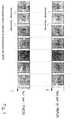
- the circuit of this invention can provide output digital signals which are sure disoverlapped by that the fall of one of them is necessary for the other to rise, as shown in Figure 7.
- circuit 1 by means of the chain circuit structure with no parallel vias shown in Figure 5 allows of easier matching of the various transistors which implement the inverters, as well as of improved accuracy in generating disoverlapped signals.
- the four delayed signals P1D, P1DN, P2D, P2DN are generated using only two capacitors (C1 and C2) instead of three as in the device shown in Figure 4, and by manipulating the parameters of the MOS transistors which produce them.
Landscapes
- Physics & Mathematics (AREA)
- Nonlinear Science (AREA)
- Electronic Switches (AREA)
Priority Applications (1)
| Application Number | Priority Date | Filing Date | Title |
|---|---|---|---|
| EP96830554A EP0840451A1 (fr) | 1996-10-30 | 1996-10-30 | Circuit générateur pour générer des signaux sans chevauchement |
Applications Claiming Priority (1)
| Application Number | Priority Date | Filing Date | Title |
|---|---|---|---|
| EP96830554A EP0840451A1 (fr) | 1996-10-30 | 1996-10-30 | Circuit générateur pour générer des signaux sans chevauchement |
Publications (1)
| Publication Number | Publication Date |
|---|---|
| EP0840451A1 true EP0840451A1 (fr) | 1998-05-06 |
Family
ID=8226047
Family Applications (1)
| Application Number | Title | Priority Date | Filing Date |
|---|---|---|---|
| EP96830554A Withdrawn EP0840451A1 (fr) | 1996-10-30 | 1996-10-30 | Circuit générateur pour générer des signaux sans chevauchement |
Country Status (1)
| Country | Link |
|---|---|
| EP (1) | EP0840451A1 (fr) |
Cited By (1)
| Publication number | Priority date | Publication date | Assignee | Title |
|---|---|---|---|---|
| US20230014288A1 (en) * | 2021-07-16 | 2023-01-19 | Changxin Memory Technologies, Inc. | Staggering signal generation circuit and integrated chip |
Citations (4)
| Publication number | Priority date | Publication date | Assignee | Title |
|---|---|---|---|---|
| EP0053014A1 (fr) * | 1980-11-20 | 1982-06-02 | Fujitsu Limited | Circuit de générateur de signaux d'horloge |
| EP0463854A1 (fr) * | 1990-06-25 | 1992-01-02 | Nec Corporation | Circuit d'attaque d'horloge |
| EP0481093A1 (fr) * | 1990-05-02 | 1992-04-22 | Kabushiki Kaisha Toshiba | Circuit de temporisation |
| US5444405A (en) * | 1992-03-02 | 1995-08-22 | Seiko Epson Corporation | Clock generator with programmable non-overlapping clock edge capability |
-
1996
- 1996-10-30 EP EP96830554A patent/EP0840451A1/fr not_active Withdrawn
Patent Citations (4)
| Publication number | Priority date | Publication date | Assignee | Title |
|---|---|---|---|---|
| EP0053014A1 (fr) * | 1980-11-20 | 1982-06-02 | Fujitsu Limited | Circuit de générateur de signaux d'horloge |
| EP0481093A1 (fr) * | 1990-05-02 | 1992-04-22 | Kabushiki Kaisha Toshiba | Circuit de temporisation |
| EP0463854A1 (fr) * | 1990-06-25 | 1992-01-02 | Nec Corporation | Circuit d'attaque d'horloge |
| US5444405A (en) * | 1992-03-02 | 1995-08-22 | Seiko Epson Corporation | Clock generator with programmable non-overlapping clock edge capability |
Non-Patent Citations (1)
| Title |
|---|
| M. ACEVES ET. AL.: "ANALOG BASIC BUILDING BLOCKS FOR COMMUNICATIONS SYSTEMS", NINETEENTH ASILOMAR CONFERENCE ON CIRCUITS SYSTEMS AND COMPUTERS, 6 November 1985 (1985-11-06), PACIFIC GROVE,CA,US, pages 398 - 402, XP002028242 * |
Cited By (1)
| Publication number | Priority date | Publication date | Assignee | Title |
|---|---|---|---|---|
| US20230014288A1 (en) * | 2021-07-16 | 2023-01-19 | Changxin Memory Technologies, Inc. | Staggering signal generation circuit and integrated chip |
Similar Documents
| Publication | Publication Date | Title |
|---|---|---|
| EP0053014B1 (fr) | Circuit de générateur de signaux d'horloge | |
| US5216289A (en) | Asynchronous reset scheme for ultra-low noise port tri-state output driver circuit | |
| EP0735688A2 (fr) | Logique adiabatique | |
| US3935474A (en) | Phase logic | |
| US4472645A (en) | Clock circuit for generating non-overlapping pulses | |
| WO1995031038A1 (fr) | Ligne a retard quasi passive a capacite commutee (sc) | |
| JPH02119427A (ja) | 出力バッファ回路 | |
| JPH05191228A (ja) | 半導体チツプ回路 | |
| JPH0628882A (ja) | サンプルホールド回路 | |
| JP7378663B2 (ja) | デジタルアナログ変換機 | |
| US4565934A (en) | Dynamic clocking system using six clocks to achieve six delays | |
| US3857045A (en) | Four-phase logic systems | |
| JPS598919B2 (ja) | バケツト・ブリゲ−ド・シフト・レジスタ装置 | |
| US6617882B2 (en) | Clocked half-rail differential logic | |
| JP3555964B2 (ja) | 信号処理回路およびそれを用いたcmos半導体集積回路 | |
| US6828826B1 (en) | Method for clock control of half-rail differential logic | |
| EP0743648A1 (fr) | Etage de sortie pour des circuits intégrés, spécialement pour mémoires électroniques | |
| EP0768759A2 (fr) | Circuit de retard analogique | |
| JPS6020632A (ja) | Nor回路 | |
| SU1034185A1 (ru) | Аналоговый ключ | |
| US6750678B2 (en) | Method for increasing the load capacity of clocked half-rail differential logic | |
| US6744283B2 (en) | Clocked half-rail differential logic with sense amplifier | |
| SU1506510A1 (ru) | Устройство дл сравнени двух частот | |
| JPH02200006A (ja) | 半導体集積回路の遅延回路 | |
| KR19980027527A (ko) | 디지털 아날로그 컨버터 |
Legal Events
| Date | Code | Title | Description |
|---|---|---|---|
| PUAI | Public reference made under article 153(3) epc to a published international application that has entered the european phase |
Free format text: ORIGINAL CODE: 0009012 |
|
| AK | Designated contracting states |
Kind code of ref document: A1 Designated state(s): DE FR GB IT |
|
| RAP3 | Party data changed (applicant data changed or rights of an application transferred) |
Owner name: STMICROELECTRONICS S.R.L. |
|
| 17P | Request for examination filed |
Effective date: 19981020 |
|
| AKX | Designation fees paid |
Free format text: DE FR GB IT |
|
| RBV | Designated contracting states (corrected) |
Designated state(s): DE FR GB IT |
|
| 17Q | First examination report despatched |
Effective date: 19990831 |
|
| STAA | Information on the status of an ep patent application or granted ep patent |
Free format text: STATUS: THE APPLICATION IS DEEMED TO BE WITHDRAWN |
|
| 18D | Application deemed to be withdrawn |
Effective date: 20020503 |