EP0840869B1 - Vehicule pouvant se deplacer dans un pipe-line - Google Patents
Vehicule pouvant se deplacer dans un pipe-line Download PDFInfo
- Publication number
- EP0840869B1 EP0840869B1 EP96914327A EP96914327A EP0840869B1 EP 0840869 B1 EP0840869 B1 EP 0840869B1 EP 96914327 A EP96914327 A EP 96914327A EP 96914327 A EP96914327 A EP 96914327A EP 0840869 B1 EP0840869 B1 EP 0840869B1
- Authority
- EP
- European Patent Office
- Prior art keywords
- vehicle
- module
- pipe
- pipeline
- probe
- Prior art date
- Legal status (The legal status is an assumption and is not a legal conclusion. Google has not performed a legal analysis and makes no representation as to the accuracy of the status listed.)
- Expired - Lifetime
Links
Images




Classifications
-
- G—PHYSICS
- G01—MEASURING; TESTING
- G01V—GEOPHYSICS; GRAVITATIONAL MEASUREMENTS; DETECTING MASSES OR OBJECTS; TAGS
- G01V3/00—Electric or magnetic prospecting or detecting; Measuring magnetic field characteristics of the earth, e.g. declination, deviation
- G01V3/18—Electric or magnetic prospecting or detecting; Measuring magnetic field characteristics of the earth, e.g. declination, deviation specially adapted for well-logging
- G01V3/26—Electric or magnetic prospecting or detecting; Measuring magnetic field characteristics of the earth, e.g. declination, deviation specially adapted for well-logging operating with magnetic or electric fields produced or modified either by the surrounding earth formation or by the detecting device
-
- F—MECHANICAL ENGINEERING; LIGHTING; HEATING; WEAPONS; BLASTING
- F16—ENGINEERING ELEMENTS AND UNITS; GENERAL MEASURES FOR PRODUCING AND MAINTAINING EFFECTIVE FUNCTIONING OF MACHINES OR INSTALLATIONS; THERMAL INSULATION IN GENERAL
- F16L—PIPES; JOINTS OR FITTINGS FOR PIPES; SUPPORTS FOR PIPES, CABLES OR PROTECTIVE TUBING; MEANS FOR THERMAL INSULATION IN GENERAL
- F16L55/00—Devices or appurtenances for use in, or in connection with, pipes or pipe systems
- F16L55/26—Pigs or moles, i.e. devices movable in a pipe or conduit with or without self-contained propulsion means
- F16L55/28—Constructional aspects
-
- G—PHYSICS
- G01—MEASURING; TESTING
- G01N—INVESTIGATING OR ANALYSING MATERIALS BY DETERMINING THEIR CHEMICAL OR PHYSICAL PROPERTIES
- G01N27/00—Investigating or analysing materials by the use of electric, electrochemical, or magnetic means
- G01N27/72—Investigating or analysing materials by the use of electric, electrochemical, or magnetic means by investigating magnetic variables
- G01N27/82—Investigating or analysing materials by the use of electric, electrochemical, or magnetic means by investigating magnetic variables for investigating the presence of flaws
-
- G—PHYSICS
- G01—MEASURING; TESTING
- G01N—INVESTIGATING OR ANALYSING MATERIALS BY DETERMINING THEIR CHEMICAL OR PHYSICAL PROPERTIES
- G01N27/00—Investigating or analysing materials by the use of electric, electrochemical, or magnetic means
- G01N27/72—Investigating or analysing materials by the use of electric, electrochemical, or magnetic means by investigating magnetic variables
- G01N27/82—Investigating or analysing materials by the use of electric, electrochemical, or magnetic means by investigating magnetic variables for investigating the presence of flaws
- G01N27/90—Investigating or analysing materials by the use of electric, electrochemical, or magnetic means by investigating magnetic variables for investigating the presence of flaws using eddy currents
- G01N27/9013—Arrangements for scanning
- G01N27/902—Arrangements for scanning by moving the sensors
-
- G—PHYSICS
- G01—MEASURING; TESTING
- G01V—GEOPHYSICS; GRAVITATIONAL MEASUREMENTS; DETECTING MASSES OR OBJECTS; TAGS
- G01V3/00—Electric or magnetic prospecting or detecting; Measuring magnetic field characteristics of the earth, e.g. declination, deviation
- G01V3/15—Electric or magnetic prospecting or detecting; Measuring magnetic field characteristics of the earth, e.g. declination, deviation specially adapted for use during transport, e.g. by a person, vehicle or boat
-
- F—MECHANICAL ENGINEERING; LIGHTING; HEATING; WEAPONS; BLASTING
- F16—ENGINEERING ELEMENTS AND UNITS; GENERAL MEASURES FOR PRODUCING AND MAINTAINING EFFECTIVE FUNCTIONING OF MACHINES OR INSTALLATIONS; THERMAL INSULATION IN GENERAL
- F16L—PIPES; JOINTS OR FITTINGS FOR PIPES; SUPPORTS FOR PIPES, CABLES OR PROTECTIVE TUBING; MEANS FOR THERMAL INSULATION IN GENERAL
- F16L2101/00—Uses or applications of pigs or moles
- F16L2101/30—Inspecting, measuring or testing
Definitions
- the invention relates to an in-pipe vehicle which can carry out an operation within a pipeline, which pipeline may be a gas carrying pipeline.
- a pipeline device includes an arrangement for forming an aperture in a liner, the device being pulled by a wire or pushed by a rod.
- a remotely controlled device has a magnetic sensor and an arangement for marking a pipe junction to allow an opening to be formed later.
- the present invention is concerned generally with an arrangement which will allow operations to be undertaken from within the pipeline, without the need for external drives, umbilicals or other connections which restrict the movement or utility of such arrangements.
- a pipeline vehicle comprising a plurality of linked modules forming a powered train for travelling within a pipeline, at least one of the modules being capable of carrying out an operation on the pipeline and wherein a module includes clamping means for holding the vehicle at a fixed point in the pipeline whilst rotational means are operable to axially rotate part or parts of the vehicle relative to the pipeline bore to align the module capable of carrying out the operation.
- a method of effecting an operation on a pipeline comprising passing a vehicle consisting of a train of separate flexibly linked modules through the pipeline to detect the presence of an item to be operated on, moving the vehicle to align a module with the item to carry out the desired operation, the alignment step including clamping the vehicle and during the clamping step effecting axial rotational movement of the module relative to the pipeline bore.
- an elongate flexible probe for insertion into and passage along an auxiliary pipe from an end remote from a main pipe and for indicating the proximity of the auxiliary pipe to a device within a main pipe, said probe including means for generating a magnetic field for detection by the device within the main pipe, indication means associated with the probe for generating a signal when the probe is adjacent the main pipe, and means to enable the probe to travel along a pipe.
- a buried cast iron gas main pipeline 1 shown in Figure 1 carries a polyethylene pipe liner 2 which has previously been inserted through excavation 3 as part of a refurbishment programme.
- a number of existing service pipe take-offs 4 each provide the source of gas to individual dwellings or other premises.
- As part of the refurbishment programme there is a need to insert a liner in each service pipe and to join this to the main liner 2.
- In order to achieve this it has been necessary in the past to make an excavation at each service connection 5 (e.g. a screwed pipe connector or a service tee) and penetrate the main liner 2 through the excavation, sealing the take off to the main using a saddle connection, having removed part of the cast iron main in that region.
- each service connection 5 e.g. a screwed pipe connector or a service tee
- the self-powered in-pipe vehicle 10 of Figure 2 includes a plurality of dissimilar individual modules 11 - 16 linked via similar linkage and suspension modules 17.
- the train of modular elements allows flexibility of operation in that each module provides a specific function which in this embodiment work together to remotely connect polyethylene gas main to service piping inserted into old metal piping (as described below). Other modular configurations would allow further tasks to be effected.
- the modular arrangement together with the suspension modules allows the degree of serpentine operation needed to negotiate bends in the pipe and to cope with the small diameter of the pipe which can be less than 150mm.
- the first module in the train is the traction module 11 which includes a motor 20 within one of the arms 22, 23 terminating in drive wheels 26 and idler wheels 25 respectively.
- the moveable arms 22 and 23 allow the wheels to contact closely the inner wall of the pipe through which it traverses and sensors within both the idler and drive wheel detect slippage which causes the traction unit to cause the arm to extend further to increase the traction affect. This can be effected by a motor driven ball screw acting on the lever arm to control the transverse load.
- the motor 20 drives the wheels via gearing and feedback on movement, direction and slippage which can be compensated by internal control.
- the traction unit provides a pushing force for the train of 80 N at a speed of 30 mm/s.
- Power for the modules including the traction module 11 is provided by the power unit 12 which incorporates a number of rechargeable batteries.
- Electrical connection to the modules is provided via the suspension unit 17 connectors.
- the suspension units 17 are provided of common construction and placed between each functional module to give the train flexibility required for small pipes.
- Each module 17 includes three spring loaded arms 30 terminating in wheels 31. In order to avoid the use of highly preloaded suspension springs, the three lever arms at one end are interconnected via a slider.
- a central shaft 33 through each suspension unit is free to rotate relative to the body. Connectors at each end allow electrical connection between all modules to be effected for power and intercommunication requirements.
- the manipulator module 13 includes three retractable extenders 40 which are controlled to extend when required beyond the manipulator's cylindrical body 41 so as to firmly support the module as it becomes wedged in the pipe.
- a motor with associated gearing (e.g. ring gear) and feedback allows the rear portion of manipulator to rotate relative to the front portion and as the modules are all mechanically linked this causes modules connected to the rear of the manipulator to axially rotate within the pipe so that they can be aligned to a certain portion of the pipe to effect a task when required.
- a 'global' rotational manipulation for all modules has been found effective rather than each module making adjustments themselves, although 'local' manipulation may be required in addition for a given module.
- the rotational manipulation can provide two 210° arcs with the body clamped against the pipe wall. Electrical connection through the rotating interface within the manipulator is provided by use of a coiled cable to avoid slip ring interference and reduce module length.
- the sensor module 14 includes a number of magnetic sensors 50 spaced around the periphery of the module for detecting a magnetic field from a source which is typically within the module 14.
- the sensors (typically 40 in number) form part of a variable reluctance magnetic circuit.
- the detectors can be of the Hall effect type.
- the hole in the offtake corresponds to the largest loss and indicates its position.
- the drill module 15 includes a motorised drill bit 60 capable of drilling a hole through the pipe, but more typically through the pipe liner.
- a 16mm hole would be suitable to access a 25mm service pipe tee.
- the fusion module 16 carries a sensor 70 (e.g. a force sensor with variable resistance when contacted by a guide wire) for detecting the guide wire in the service pipe liner (for reasons described below) and a heater device 71 for effecting a seal between the main liner and the service pipe liner.
- the manipulator module 13 allows the rotation by 180° of the train including module 16 to allow the sensing and sealing functions to be effected.
- a master controller circuit can be located within the power module 12 and individual modules have localised control circuits to effect tasks associated with their particular devices.
- the master controller and the module controllers can be formed from a common approach using a hierarchial modular organisation of control and monitor process operating on independent communicating modules.
- the master controller is aware of operations being effected by individual modules and ensures the required tasks are carried out.
- Each module control arrangement includes a control board sensor and actuators of common hardware design with operation mode selection under software control. Such a module control system is shown in Figure 3.
- Analogue module sensors 80 connect to a programmable peripheral interface 81 which carries an onboard analog to digital converter (ADC) and digital I/O lines.
- Digital sensors 89 connect to the digital inputs.
- Information from the interface is made available to microprocessor 82 which includes associated data storage RAM 83 and program storage ROM 84.
- a communication link 85 is also available to communicate with other modules.
- the microprocessor accesses sensor information via interface 81 (e.g. type HD631408) and controls the loads 90, (e.g. motors or other operational devices such as heaters) via decoder 86 and driver circuits 87. Current monitoring feedback is provided via line 88.
- Power supply regulation block 92 ensures trouble-free power supply requirements.
- the microprocessor can be a T225 transputer contains a RISC CPU (16bit 25MHZ) and interprocessor communications links.
- Power for the devices can be high capacity nickel cadmium rechargeable batteries of the 'pancake' configuration.
- the system can be sufficiently intelligent to carry out the tasks without external control although with a radio link (e.g. 1.394GHZ) it is possible to send information on operations being effected to an 'above ground' station using the pipeline as a waveguide. Return signals could be sent to override or halt tasks if they are detected as being inappropriate.
- a radio link e.g. 1.394GHZ
- the train of modules is driven by module 11 along the pipe until detector module 14 detects a service tee through the main liner.
- the aperture will typically be at the highest point in the pipe wall but the actual position is determined by the detectors.
- the train will then move on until the drill module 15 is at the correct position beneath the tee.
- the manipulator module 13 then activates its extenders 40 to clamp the module. If the drill is not determined to be in front of the aperture from earlier calculations, the module then rotates in an arc to line up the drill.
- the manipulator module 13 retracts its extenders and the train moves forwards until the fusion module 16 is determined to be located beneath the service tee.
- the manipulator module 13 again activates its extenders and clamps itself to the main pipe. A rotation of the module is effected if it is determined that this is necessary to locate the detector 70 in front of the tee.
- the hole already drilled in the main liner allows the service pipe liner to be inserted through the service pipe using a very flexible guide wire.
- the service liner has at its front end a tapered lead component formed from cross-linked polyethylene. The presence of the guide wire confirms to the detector that the correct service tee is being refurbished. Once the lead end is located in the drilled hole, the guide wire is removed, indicating that the jointing step can be effected.
- the manipulator 13 rotates through 180° to locate the heater device 71 on the fusion module 16 adjacent to the region of the service liner end, within the main liner hole and electric power is applied to the heater to fuse the joint in the liners by raising the temperature to the crystalline melt stage, causing the service liner end-piece to expand and fuse simultaneously to the main liner.
- the manipulator module contracts its extenders 40 and the train of modules moved on along the pipe until it detects the presence of the next service pipe, when the operations can proceed once again.
- the magnetic source for sensor module 14 may be a coil producing a field which is radial with respect to the wall of the main which is detected as falling in the region of the offtake, it is possible to use a permanent magnet arrangement as an alternative within the module.
- FIG. 4 shows such an arrangement using bar magnets 100.
- a bar magnet 100 associated with each sensor 102 (a Hall effect device having a linear output).
- Each sensor 102 is protected by potting compound 103.
- Each sensor 102 is mounted on a sledge 104 which is reciprocable radially and urged outwardly by two compression springs 106, 108.
- Each sledge 104 is guided by a pin 110 fixed to the sledge 104 and reciprocable in a bore 112 in a central fixed body 114.
- the body 114 is part of a module 116 equivalent to module 14 of Figure 2 which forms the train which is movable through main 10.
- the upper half of Figure 4 shows a sledge 104 in its innermost position as dictated by the minimum radius which the liner 12 presents.
- the lower half of Figure 4 shows a sledge 104 in its outermost position as dictated by the maximum radius which the line 12 presents.
- Figure 4 is presented merely for information regarding the inward and outward movement of the sledges 104.
- the module 116 occupies a central position in the main. As a result, all the sledges 104 occupy similar radial positions with respect to the body 114.
- Each sledge 104 is retained by pins 120, 122 fixed in the body 114 and projecting into slideways 124, 126 in the sledge 104.
- Each slideway 124, 126 terminates in an axially extending clearance hole 128, 130.
- Each sledge 104 can be removed from the body 114 by holding it in its radially innermost position, as shown in the upper half of Figure 2 and knocking the pins 120, 122 inwardly into the clearance holes 128, 130.
- Each sensor 102 has a multi-conductor lead 140 by which the sensor 102 is connected to the detector to electronics (not shown) housed in the housing 142 secured to one end of the body 114.
- the magnetic lines of force generated by the bar magnet 100 leave the magnet 100 at its right-hand end and are turned radially outwardly by a block 150 of ferromagnetic material.
- the lines of force pass through the liner 12 and enter the cast iron main 10.
- the lines of force travel leftward through the main 10, then turn radially inward and pass through the liner 12, through the sensor 102 and enter another block of ferromagnetic material 152.
- the direction of the lines of magnetic lines of force change from radially inward to horizontal in the block 152 and then the lines of force enter the left hand end of the magnet 100.
- a block 154 of plastics material bridges the gap between the two blocks 150, 152 of ferromagnetic material.
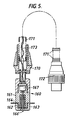
- Figure 5 shows an elongate probe 160 including a head portion 161.
- the head portion includes a magnetic source coil 162 having a ferrite core and located within brass housing 163.
- a plastic guide washer 164 e.g. tri-cornered PTFE
- switch activator 166 is provided coupled to switch 167.
- the head is connected to steel housing 170 to which is coupled a flexible coil-like spring tube 171 which terminates in plug 172.
- the hollow tube 171 carries the connecting wires 173 for the switch and coil.
- the tube 171 is typically about 4 metres long and is sufficiently flexible to pass through bends and other potential obstacles in the pipe.
- the plug 172 connects with the transmission electronics within housing 180 via socket 181.
- the electronic circuit includes a waveform generator IC, 187 (e.g. ICL 8038) connected to a battery power source 182 via switch 183.
- Lamps 184 and 185 e.g. LEDs indicate circuit operation and when the probe contacts the main liner.
- the generator produces an output frequency of about 35 KHz at 14 volts peak to peak.
- the light 185 is illuminated and the probe is in the correct position for the in pipe vehicle to detect the ac magnetic field. Once the vehicle has detected the source, it can send a signal to the surface to allow the probe to be partially withdrawn while the drilling operation is being effected.
- the detector module 14 of the in pipe vehicle is modified to detect the source within the service pipe and can include an arrangement of the form shown in Figure 7. It could alternatively be mounted within the drill module.
- the coil assembly includes a large diameter wound coil 190 which is the course position detector coil.
- a second fine position coil 191 assembly includes two separate windings at 90° angles to give an 'x' and 'y' co-ordinate coil 192 and 193 and associated capacitors 194, 195 and resistor 196.
- the signal field information detected by the coils 190, 191 is received by the processing circuit of Figure 8.
- This circuit includes amplifiers 200 and 201 and RMS to DC converters 202, 203 and filters 204, 205.
- the dc outputs are converted into digital form via A to D converter 206 before handling by the vehicle computer system 207 (of the type shown in Figure 3).
- the robot In operation, the robot is driven down the supply pipe towards the magnetic field radiated by the source located in the service tee.
- the induced voltage in the coarse coil increases and reaches a maximum as the flux cuts it at right angles. It falls to a minimum as it passes through the centre of the source and the axis of the field is in line with the coil.
- the service tee is adjacent to the coil but it can be at any location around the circumference of the pipe.
- This coarse position is logged by the robot vehicle Transputer (microprocessor) and used to reposition the drill module bringing the fine coil to the same position.
- the Transputer When the fine coils are in the pipe section identified by the coarse coil, the Transputer initiates a search pattern, to locate the centre of the source coil. This tracks the drill module in rotational and longitudinal directions until the output from the coils is at a minimum or null.
- the drill module When the fine coils are positioned at the centre of the source coil the drill module is rotated by 90 degrees which brings the drill bit in line with the centre of the source coil. The process is completed by energising the drill to cut a hole in the PE liner to take the new PE service pipe as described earlier.
- the probe in the service pipe can be removed and replaced with the guide wire which carries the service pipe liner, before fusing this liner to the main pipe liner.
Landscapes
- Engineering & Computer Science (AREA)
- Life Sciences & Earth Sciences (AREA)
- Chemical & Material Sciences (AREA)
- Physics & Mathematics (AREA)
- General Physics & Mathematics (AREA)
- Remote Sensing (AREA)
- Biochemistry (AREA)
- Analytical Chemistry (AREA)
- General Health & Medical Sciences (AREA)
- Health & Medical Sciences (AREA)
- Immunology (AREA)
- Pathology (AREA)
- Electrochemistry (AREA)
- General Engineering & Computer Science (AREA)
- Chemical Kinetics & Catalysis (AREA)
- Environmental & Geological Engineering (AREA)
- Geology (AREA)
- General Life Sciences & Earth Sciences (AREA)
- Geophysics (AREA)
- Combustion & Propulsion (AREA)
- Electromagnetism (AREA)
- Mechanical Engineering (AREA)
- Investigating Or Analyzing Materials By The Use Of Magnetic Means (AREA)
- Manipulator (AREA)
- Geophysics And Detection Of Objects (AREA)
- Measurement Of Length, Angles, Or The Like Using Electric Or Magnetic Means (AREA)
- Investigating Or Analyzing Materials By The Use Of Ultrasonic Waves (AREA)
- Earth Drilling (AREA)
- Lining Or Joining Of Plastics Or The Like (AREA)
- Length Measuring Devices With Unspecified Measuring Means (AREA)
- A Measuring Device Byusing Mechanical Method (AREA)
Claims (34)
- Véhicule pour pipeline (10) comportant une pluralité de modules (11 à 16) reliés entre eux et formant un train motorisé destiné à se déplacer à l'intérieur d'un pipeline, au moins un des modules (15) étant capable d'effectuer une intervention sur le pipeline, et dans lequel un module comprend des moyens de serrage (40) destinés à maintenir le véhicule en un point fixe du pipeline tandis que des moyens d'entraínement en rotation sont aptes à fonctionner pour faire tourner axialement une partie ou des parties du véhicule par rapport à l'alésage du pipeline pour aligner le module (15) capable d'effectuer l'intervention.
- Véhicule selon la revendication 1, dans lequel un module de traction (11) fournit l'énergie motrice requise pour le véhicule et comprend des moyens d'entraínement pour faire varier le degré de frottement entre le module de traction et le pipeline.
- Véhicule selon la revendication 1 ou 2, dans lequel un module (14) comprend des moyens de détection pour détecter une jonction de tuyau à l'intérieur du pipeline principal.
- Véhicule selon la revendication 3, dans lequel les moyens de détection comprennent une pluralité de détecteurs magnétiques (50 ; 102) pour détecter l'emplacement circonférentiel relatif de la jonction à l'intérieur du tuyau.
- Véhicule selon la revendication 3 ou 4, dans lequel une source magnétique (100) est transportée à l'intérieur du module de détection.
- Véhicule selon la revendication 3 ou 4, dans lequel la source magnétique comprend une bobine (162) pour engendrer un champ magnétique.
- Véhicule selon la revendication 3 ou 4, dans lequel une source magnétique est prévue à l'extérieur du module en utilisant du courant alternatif pour engendrer un champ magnétique.
- Véhicule selon l'une quelconque des revendications précédentes, dans lequel un module comprend des moyens de perçage (60) prévus pour faire réaliser une ouverture à travers ou dans le pipeline ou une garniture prévue à l'intérieur de ce dernier.
- Véhicule selon l'une quelconque des revendications précédentes, dans lequel un module comprend des moyens (71) pour chauffer un tuyau en plastique pour faire réaliser un joint entre une tuyauterie principale et une tuyauterie de plus faible diamètre s'étendant à partir de celle-ci.
- Véhicule selon l'une quelconque des revendications précédentes, dans lequel un module (13) comporte un corps cylindrique allongé ayant une première portion cylindrique configurée pour serrer le pipeline et une seconde portion cylindrique coaxiale avec celle-ci et configurée pour tourner tandis que la première portion serre le pipeline.
- Véhicule selon la revendication 10, dans lequel le diamètre du corps cylindrique n'est pas supérieur à 150 mm.
- Véhicule selon l'une quelconque des revendications précédentes, comprenant un dispositif informatique (82) à l'intérieur d'un module pour recevoir une sortie en provenance d'une pluralité de détecteurs (80, 89) par l'intermédiaire de moyens formant interface (81), lesdits moyens informatiques étant configurés pour déterminer automatiquement, premièrement, qu'une jonction de pipeline a été atteinte, deuxièmement, pour déterminer l'orientation de la jonction et, troisièmement, pour déterminer le degré de rotation axiale et l'ampleur du déplacement vers l'avant nécessaires à l'alignement du module capable d'effectuer l'intervention sur le pipeline.
- Véhicule selon la revendication 12, comprenant des moyens de transmission pour communiquer entre le véhicule et la surface, lesdits moyens de transmission étant configurés pour utiliser le pipeline en tant que guide d'ondes.
- Véhicule selon l'une quelconque des revendications précédentes, comprenant une pluralité de modules dissemblables (13 à 16) destinés chacun à assurer une fonction différente au niveau du pipeline.
- Véhicule selon la revendication 14, comprenant un module (14) pour détecter un embranchement, un autre module (13) pour serrer le véhicule et encore un autre module (15) pour couper à travers une garniture prévue dans le pipeline.
- Véhicule selon l'une quelconque des revendications précédentes, dans lequel des liaisons flexibles (30-33) sont prévues pour aider à manoeuvrer le véhicule.
- Véhicule selon la revendication 16, dans lequel les liaisons sont portées sur une pluralité de modules intermédiaires à roues (17).
- Procédé d'intervention sur un pipeline, consistant à faire passer un véhicule constitué d'un train de modules individuels liés de façon flexible dans le pipeline afin de détecter la présence d'un objet sur lequel il convient d'intervenir, à déplacer le véhicule de façon a aligner un module avec l'objet afin d'effectuer l'intervention souhaitée, l'étape d'alignement consistant à serrer le véhicule et, au cours de l'étape de serrage, à effectuer un mouvement de rotation axiale du module par rapport à l'alésage du pipeline.
- Procédé selon la revendication 18, dans lequel le module destiné à effectuer l'intervention est déplacé longitudinalement et axialement afin de faciliter l'alignement.
- Procédé selon la revendication 18 ou 19, dans lequel un module de perçage est aligné dans le pipeline afin d'effectuer le perçage d'une garniture de pipeline principale.
- Procédé selon la revendication 20, dans lequel un module de scellement est aligné dans le pipeline pour sceller une garniture de pipeline auxiliaire à la garniture principale.
- Véhicule automoteur et auto-commandé pour pipeline selon la revendication 1 ou 2, comportant une portion de corps généralement cylindrique configurée pour se déplacer généralement coaxialement à l'intérieur de l'alésage du pipeline et comprenant des moyens de détection (50, 102) pour détecter la présence d'une jonction de tuyau dans un pipeline principal, des moyens (60) pour former une ouverture dans une garniture à l'intérieur du pipeline principal, et dans lequel les moyens d'entraínement en rotation font tourner une portion du corps axialement par rapport à l'alésage du pipeline afin d'aligner les moyens de formation d'ouverture avec la jonction de tuyau avant de former l'ouverture au niveau de la jonction de tuyau, sans nécessiter de moyens de télécommande.
- Véhicule selon la revendication 22, dans lequel les moyens de détection sont constitués d'un détecteur magnétique (50, 102) pour détecter la présence d'un champ électrique dans la région de la jonction.
- Véhicule selon la revendication 23, dans lequel les moyens de détection comprennent une bobine de détection approximative (190) et une bobine de détection précise (191) pour faciliter la détection de l'emplacement.
- Véhicule selon la revendication 23, dans lequel le détecteur comprend une source magnétique (100).
- Véhicule selon l'une quelconque des revendications 22 à 25, dans lequel le véhicule comporte une pluralité de modules articulés reliés par des modules de suspension intermédiaires (17).
- Véhicule selon l'une quelconque des revendications 22 à 26, comprenant des moyens de scellement (16) pour sceller une garniture de pipeline auxiliaire à la garniture principale.
- Véhicule selon l'une quelconque des revendications 22 à 27 comportant une pluralité de modules reliés (11 à 16) conçus en vue d'un déplacement sinueux dans le pipeline.
- Véhicule selon l'une quelconque des revendications 22 à 28, dans lequel des moyens d'auto-commande (80 à 90) comprennent un dispositif informatique (82) raccordé aux moyens de détection (50) pour déterminer que la jonction de tuyau a été atteinte et pour déterminer l'orientation de la jonction afin de commander les moyens (13) pour faire tourner le corps axialement afin d'aligner les moyens de formation d'ouverture.
- Véhicule selon l'une quelconque des revendications 22 à 29 comprenant des moyens de commande de frottement (22 à 26) pour faire varier le degré de frottement entre le module de traction et le pipeline.
- Sonde flexible allongée (160) destinée à être introduite dans une tuyauterie auxiliaire et à passer le long de celle-ci, à partir d'une extrémité éloignée d'un pipeline principal, et à indiquer la proximité de la tuyauterie auxiliaire par rapport à un dispositif se trouvant dans le pipeline principal, ladite sonde comprenant des moyens (162) pour engendrer un champ magnétique en vue de sa détection par le dispositif à l'intérieur du pipeline principal, des moyens d'indication (185) associés à la sonde pour générer un signal lorsque la sonde est à proximité du pipeline principal et des moyens (172, 173) pour permettre à la sonde de se déplacer le long d'une tuyauterie.
- Sonde selon la revendication 31, comprenant un tube flexible en forme de ressort hélicoïdal (171) pour faciliter le passage de la sonde dans la tuyauterie auxiliaire.
- Sonde selon la revendication 31 ou 32, dans laquelle les moyens pour générer un champ magnétique comprennent une bobine (162) avec un circuit électronique (187) pour générer un signal de courant alternatif.
- Sonde selon la revendication 31, 32 ou 33, dans laquelle les moyens de génération d'un signal comprennent un interrupteur (167) qui est apte à fonctionner lorsque la sonde entre en contact avec la conduite principale ou la garniture principale.
Applications Claiming Priority (3)
| Application Number | Priority Date | Filing Date | Title |
|---|---|---|---|
| GB9510434A GB2301187B (en) | 1995-05-22 | 1995-05-22 | Method of and apparatus for locating an anomaly in a duct |
| GB9510434 | 1995-05-22 | ||
| PCT/GB1996/001214 WO1996037727A1 (fr) | 1995-05-22 | 1996-05-21 | Vehicule pouvant se deplacer dans un pipe-line |
Publications (2)
| Publication Number | Publication Date |
|---|---|
| EP0840869A1 EP0840869A1 (fr) | 1998-05-13 |
| EP0840869B1 true EP0840869B1 (fr) | 2002-03-06 |
Family
ID=10774908
Family Applications (1)
| Application Number | Title | Priority Date | Filing Date |
|---|---|---|---|
| EP96914327A Expired - Lifetime EP0840869B1 (fr) | 1995-05-22 | 1996-05-21 | Vehicule pouvant se deplacer dans un pipe-line |
Country Status (8)
| Country | Link |
|---|---|
| US (4) | US5878783A (fr) |
| EP (1) | EP0840869B1 (fr) |
| JP (2) | JP3561276B2 (fr) |
| CA (2) | CA2173193A1 (fr) |
| DE (1) | DE69619678T2 (fr) |
| ES (1) | ES2174070T3 (fr) |
| GB (2) | GB2301187B (fr) |
| WO (1) | WO1996037727A1 (fr) |
Cited By (2)
| Publication number | Priority date | Publication date | Assignee | Title |
|---|---|---|---|---|
| WO2012102611A1 (fr) | 2011-01-25 | 2012-08-02 | Jelcer-Ip B.V. | Appareil de déplacement dans un conduit et son utilisation |
| CN109612366A (zh) * | 2018-11-21 | 2019-04-12 | 山东里能鲁西矿业有限公司 | 一种新型可回收顶板离层仪 |
Families Citing this family (168)
| Publication number | Priority date | Publication date | Assignee | Title |
|---|---|---|---|---|
| US6857486B2 (en) * | 2001-08-19 | 2005-02-22 | Smart Drilling And Completion, Inc. | High power umbilicals for subterranean electric drilling machines and remotely operated vehicles |
| GB2301187B (en) * | 1995-05-22 | 1999-04-21 | British Gas Plc | Method of and apparatus for locating an anomaly in a duct |
| BR9610373A (pt) | 1995-08-22 | 1999-12-21 | Western Well Toll Inc | Ferramenta de furo de tração-empuxo |
| GB9614761D0 (en) * | 1996-07-13 | 1996-09-04 | Schlumberger Ltd | Downhole tool and method |
| WO1999000621A1 (fr) * | 1997-06-26 | 1999-01-07 | Gas Research Institute | Systeme pour inspecter des conduites de gaz en service |
| CA2218436A1 (fr) * | 1997-10-15 | 1999-04-15 | Consolidated Edison Company Of New York, Inc. | Dispositif servant a reparer les tuyaux |
| US6240965B1 (en) * | 1998-04-24 | 2001-06-05 | Link-Pipe (H.K.), Ltd. | Apparatus for repair of high temperature and pressure conduits, method for repairing high temperature and pressure conduits, and a sealing device for repairing high temperature and pressure conduits |
| AR018459A1 (es) * | 1998-06-12 | 2001-11-14 | Shell Int Research | Metodo y disposicion para mover equipos hacia y a traves de un conducto y dispositivo de vaiven para ser usado en dicha disposicion |
| BR9908000A (pt) | 1998-12-18 | 2002-01-15 | Western Well Tool Inc | Hélice de tração eletro-hidraulicamente controlada |
| US6347674B1 (en) * | 1998-12-18 | 2002-02-19 | Western Well Tool, Inc. | Electrically sequenced tractor |
| FR2790087B1 (fr) * | 1999-02-19 | 2001-04-20 | Coflexip | Procede et dispositif de mesure in situ de la distance entre deux elements donnes dans une conduite tubulaire |
| NO320782B1 (no) * | 1999-03-22 | 2006-01-30 | Aatechnology As | Fremdriftsmekanisme for lange hulrom og ror |
| US6820653B1 (en) * | 1999-04-12 | 2004-11-23 | Carnegie Mellon University | Pipe inspection and repair system |
| US9586699B1 (en) | 1999-08-16 | 2017-03-07 | Smart Drilling And Completion, Inc. | Methods and apparatus for monitoring and fixing holes in composite aircraft |
| NO311100B1 (no) * | 1999-10-26 | 2001-10-08 | Bakke Technology As | Apparat for bruk ved mating av et roterende nedihullsverktöy, samt anvendelse av apparatet |
| US6626447B2 (en) * | 2000-01-28 | 2003-09-30 | Barnard Construction Co., Inc. | Pipeline patch trolley |
| US6464003B2 (en) | 2000-05-18 | 2002-10-15 | Western Well Tool, Inc. | Gripper assembly for downhole tractors |
| US6450104B1 (en) * | 2000-04-28 | 2002-09-17 | North Carolina State University | Modular observation crawler and sensing instrument and method for operating same |
| FR2808491B1 (fr) * | 2000-05-04 | 2002-08-09 | Cie Du Sol | Un chariot automoteur apte a se deplacer dans une galerie cylindrique |
| FR2812067B1 (fr) * | 2000-07-18 | 2003-05-16 | Commissariat Energie Atomique | Robot mobile apte a travailler dans des tuyaux ou d'autres passages etroits |
| US8245796B2 (en) * | 2000-12-01 | 2012-08-21 | Wwt International, Inc. | Tractor with improved valve system |
| US7121364B2 (en) * | 2003-02-10 | 2006-10-17 | Western Well Tool, Inc. | Tractor with improved valve system |
| GB2413816B (en) | 2000-12-01 | 2006-01-04 | Western Well Tool Inc | Tractor with improved valve system |
| CA2354226A1 (fr) | 2001-01-31 | 2002-07-31 | Cal Holland | Appareil robotique et methode d'entretien non destructif de canalisations croisees |
| US20020113870A1 (en) * | 2001-02-16 | 2002-08-22 | Mueckl Gareth J. | Pipeline televising apparatus with wireless remote controller |
| CA2440344C (fr) * | 2001-03-07 | 2007-06-26 | Carnegie Mellon University | Systeme de controle robotique de conduites de gaz |
| WO2002093875A2 (fr) * | 2001-05-11 | 2002-11-21 | Wildseed, Ltd. | Procede et appareil d'association d'une commande recue a une commande de realisation d'actions avec un dispositif mobile de telecommunication |
| US6431291B1 (en) | 2001-06-14 | 2002-08-13 | Western Well Tool, Inc. | Packerfoot with bladder assembly having reduced likelihood of bladder delamination |
| US6427602B1 (en) | 2001-07-02 | 2002-08-06 | Westinghouse Savannah River Company, Llc | Pipe crawler apparatus |
| US9625361B1 (en) | 2001-08-19 | 2017-04-18 | Smart Drilling And Completion, Inc. | Methods and apparatus to prevent failures of fiber-reinforced composite materials under compressive stresses caused by fluids and gases invading microfractures in the materials |
| US8515677B1 (en) | 2002-08-15 | 2013-08-20 | Smart Drilling And Completion, Inc. | Methods and apparatus to prevent failures of fiber-reinforced composite materials under compressive stresses caused by fluids and gases invading microfractures in the materials |
| US7182025B2 (en) | 2001-10-17 | 2007-02-27 | William Marsh Rice University | Autonomous robotic crawler for in-pipe inspection |
| US7210364B2 (en) * | 2001-10-17 | 2007-05-01 | Fathi Hassan Ghorbel | Autonomous robotic crawler for in-pipe inspection |
| US6832164B1 (en) | 2001-11-20 | 2004-12-14 | Alfred Stella | Sewerage pipe inspection vehicle having a gas sensor |
| US6715559B2 (en) | 2001-12-03 | 2004-04-06 | Western Well Tool, Inc. | Gripper assembly for downhole tractors |
| DE10210746C1 (de) * | 2002-03-12 | 2003-10-16 | Ndt System & Services Ag | Segment für einen Sensorträgerkörper eines Molches |
| US7498796B2 (en) * | 2002-05-09 | 2009-03-03 | The Boeing Company | Magnetic indexer for high accuracy hole drilling |
| US7137465B1 (en) * | 2002-10-02 | 2006-11-21 | The Charles Stark Draper Laboratory, Inc. | Crawler device |
| US7143659B2 (en) * | 2002-12-17 | 2006-12-05 | Pinnacle West Capital Corporation | Pipe-inspection system |
| RU2242739C2 (ru) * | 2003-01-21 | 2004-12-20 | Государственное образовательное учреждение высшего профессионального образования Тюменский государственный нефтегазовый университет | Способ испытания оболочек и устройство для его осуществления |
| US6891477B2 (en) | 2003-04-23 | 2005-05-10 | Baker Hughes Incorporated | Apparatus and methods for remote monitoring of flow conduits |
| US7042184B2 (en) * | 2003-07-08 | 2006-05-09 | Board Of Regents Of The University Of Nebraska | Microrobot for surgical applications |
| US7126303B2 (en) * | 2003-07-08 | 2006-10-24 | Board Of Regents Of The University Of Nebraska | Robot for surgical applications |
| US7960935B2 (en) | 2003-07-08 | 2011-06-14 | The Board Of Regents Of The University Of Nebraska | Robotic devices with agent delivery components and related methods |
| NZ529182A (en) * | 2003-12-20 | 2007-02-23 | Colin Brian Nicholson | Self-propelled vehicle for use in a conduit |
| US7143843B2 (en) * | 2004-01-05 | 2006-12-05 | Schlumberger Technology Corp. | Traction control for downhole tractor |
| US7392859B2 (en) * | 2004-03-17 | 2008-07-01 | Western Well Tool, Inc. | Roller link toggle gripper and downhole tractor |
| KR100662341B1 (ko) * | 2004-07-09 | 2007-01-02 | 엘지전자 주식회사 | 디스플레이 장치 및 그의 색 재현 방법 |
| US7720570B2 (en) * | 2004-10-01 | 2010-05-18 | Redzone Robotics, Inc. | Network architecture for remote robot with interchangeable tools |
| CA2595453C (fr) * | 2005-01-18 | 2016-02-23 | Redzone Robotics, Inc. | Plate-forme mobile d'inspection autonome |
| US8170715B1 (en) | 2005-01-25 | 2012-05-01 | Redzone Robotics, Inc. | Methods and devices for automated work in pipes based on impedance control |
| US7624808B2 (en) | 2006-03-13 | 2009-12-01 | Western Well Tool, Inc. | Expandable ramp gripper |
| US8679096B2 (en) | 2007-06-21 | 2014-03-25 | Board Of Regents Of The University Of Nebraska | Multifunctional operational component for robotic devices |
| US9579088B2 (en) * | 2007-02-20 | 2017-02-28 | Board Of Regents Of The University Of Nebraska | Methods, systems, and devices for surgical visualization and device manipulation |
| WO2007149559A2 (fr) | 2006-06-22 | 2007-12-27 | Board Of Regents Of The University Of Nebraska | dispositifs robotiques pouvant être couplés magnétiquement et procédés associés |
| US20080053663A1 (en) * | 2006-08-24 | 2008-03-06 | Western Well Tool, Inc. | Downhole tool with turbine-powered motor |
| US20080217024A1 (en) * | 2006-08-24 | 2008-09-11 | Western Well Tool, Inc. | Downhole tool with closed loop power systems |
| WO2008034144A2 (fr) * | 2006-09-15 | 2008-03-20 | Redzone Robotics, Inc. | Modélisateur de trou d'homme |
| CN101626946B (zh) * | 2006-11-13 | 2013-06-05 | 雷神萨科斯公司 | 用于轻型机器人车辆的悬架系统和该车辆的支承方法 |
| EP2476604B1 (fr) * | 2006-11-13 | 2013-08-21 | Raytheon Company | Chenille robotisée dotée d'un bras mobile |
| CN101583839A (zh) * | 2006-11-13 | 2009-11-18 | 雷神萨科斯公司 | 具有可选择性地伸出和缩回的感测配件的无人驾驶地面机器人车辆 |
| DE602007007807D1 (de) * | 2006-11-13 | 2010-08-26 | Raytheon Sarcos Llc | Vielseitig verwendbares endlosband für leichte mobile roboter |
| US7748476B2 (en) | 2006-11-14 | 2010-07-06 | Wwt International, Inc. | Variable linkage assisted gripper |
| US20080245258A1 (en) * | 2007-04-06 | 2008-10-09 | General Electric Company | Pressure-balanced electric motor wheel drive for a pipeline tractor |
| WO2008137953A1 (fr) | 2007-05-07 | 2008-11-13 | Raytheon Sarcos, Llc | Procédé pour fabriquer une structure complexe |
| EP2146826A2 (fr) * | 2007-05-08 | 2010-01-27 | Raytheon Sarcos, LLC | Mappage de primitive variable pour chenille robotique |
| FR2916852B1 (fr) * | 2007-05-30 | 2009-09-11 | Snecma Sa | Reperage de points d'interet sur une zone de la surface d'une piece et application a l'optimisation de la trajectoire et de l'angulation des sondes a courants de foucault |
| GB0712205D0 (en) * | 2007-06-23 | 2007-08-01 | Oliver Crispin Robotics Ltd | Improvements in and relating to robotoc arms |
| US20090025988A1 (en) * | 2007-07-10 | 2009-01-29 | Jacobsen Stephen C | Serpentine Robotic Crawler Having A Continuous Track |
| CN101784435B (zh) * | 2007-07-10 | 2013-08-28 | 雷神萨科斯公司 | 模块化机器人履带车 |
| EP2170564A4 (fr) | 2007-07-12 | 2015-10-07 | Univ Nebraska | Procédés et systèmes d'actionnement dans des dispositifs robotiques |
| CA2695619C (fr) * | 2007-08-15 | 2015-11-24 | Board Of Regents Of The University Of Nebraska | Dispositifs medicaux modulaires et cooperatifs et systemes et procedes apparentes |
| JP2010536435A (ja) * | 2007-08-15 | 2010-12-02 | ボード オブ リージェンツ オブ ザ ユニバーシティ オブ ネブラスカ | 医療用膨張、取り付けおよび送達装置、ならびに関連する方法 |
| US20090091278A1 (en) * | 2007-09-12 | 2009-04-09 | Michael Montois | Downhole Load Sharing Motor Assembly |
| US8020460B1 (en) | 2008-02-11 | 2011-09-20 | Hoyt Philip M | Sensor housing and mount for in-line inspection tool |
| US7733085B2 (en) * | 2008-02-11 | 2010-06-08 | Electromechanical Technologies, Inc. | Flangeless canister for in-line inspection tool |
| US20090307891A1 (en) * | 2008-06-17 | 2009-12-17 | Ge-Hitachi Nuclear Energy Americas Llc | Method and apparatus for remotely inspecting and/or treating welds, pipes, vessels and/or other components used in reactor coolant systems or other process applications |
| PT2352981E (pt) * | 2008-11-03 | 2015-08-27 | Redzone Robotics Inc | Dispositivo para inspeção de cano e método de utilização do mesmo |
| US8392036B2 (en) * | 2009-01-08 | 2013-03-05 | Raytheon Company | Point and go navigation system and method |
| US8317555B2 (en) * | 2009-06-11 | 2012-11-27 | Raytheon Company | Amphibious robotic crawler |
| US8935014B2 (en) * | 2009-06-11 | 2015-01-13 | Sarcos, Lc | Method and system for deploying a surveillance network |
| US8653811B2 (en) * | 2009-06-26 | 2014-02-18 | Tdw Delaware Inc. | Pipeline inspection tool with oblique magnetizer |
| CZ2009480A3 (cs) | 2009-07-24 | 2010-11-24 | Ceské vysoké ucení technické v Praze - Fakulta elektrotechnická | Robot pro cištení a inspekci potrubí a ovládací jednotka pro jeho rízení |
| US8485278B2 (en) * | 2009-09-29 | 2013-07-16 | Wwt International, Inc. | Methods and apparatuses for inhibiting rotational misalignment of assemblies in expandable well tools |
| CA2784883A1 (fr) * | 2009-12-17 | 2011-06-23 | Board Of Regents Of The University Of Nebraska | Dispositifs medicaux modulaires et utilisables en interaction et systemes et procedes afferents |
| US8215844B1 (en) | 2010-05-17 | 2012-07-10 | Pure Technologies (U.S.) Inc. | Debris resistant bearing system and method |
| US9326663B2 (en) | 2010-06-17 | 2016-05-03 | Covidien Lp | Endoluminal crawler |
| JP2014529414A (ja) | 2010-08-06 | 2014-11-13 | ボード オブ リージェンツ オブ ザ ユニバーシティ オブ ネブラスカ | 自然開口部手術用材料の取扱または送達のための方法およびシステム |
| KR101014346B1 (ko) * | 2010-08-11 | 2011-02-15 | (주)엔티렉스 | 뱀형 로봇 |
| KR101020944B1 (ko) * | 2010-08-30 | 2011-03-09 | 한국원자력연구원 | 전열관 검사케이블 및 이의 삽입력 해석방법 |
| KR101215539B1 (ko) * | 2010-09-03 | 2013-01-09 | 삼성중공업 주식회사 | 배관 내부 검사용 이동 로봇과 이를 이동시키기 위한 이동 장치 |
| DE102010044465A1 (de) * | 2010-09-06 | 2012-03-08 | I.S.T. Innovative Sewer Technologies Gmbh | Vorrichtung zum Sanieren eines Rohres |
| CN102182895B (zh) * | 2011-03-14 | 2013-11-20 | 中国石油大学(华东) | 输气管道在线内检测器旋转推进系统 |
| WO2012130319A1 (fr) * | 2011-03-31 | 2012-10-04 | The Safer Plug Company Limited | Dispositif de propulsion |
| WO2012130318A1 (fr) * | 2011-03-31 | 2012-10-04 | The Safer Plug Company Limited | Outil de pipeline |
| WO2013048595A1 (fr) | 2011-06-10 | 2013-04-04 | Board Of Regents Of The University Of Nebraska | Procédés, systèmes et dispositifs relatifs à des effecteurs terminaux chirurgicaux |
| EP3588217A1 (fr) | 2011-07-11 | 2020-01-01 | Board of Regents of the University of Nebraska | Dispositifs chirurgicaux robotisés, systèmes et procédés associés |
| EP3730031A1 (fr) | 2011-10-03 | 2020-10-28 | Board of Regents of the University of Nebraska | Dispositifs chirurgicaux robotisés et systèmes |
| US9447648B2 (en) | 2011-10-28 | 2016-09-20 | Wwt North America Holdings, Inc | High expansion or dual link gripper |
| EP2806941B1 (fr) | 2012-01-10 | 2021-10-27 | Board of Regents of the University of Nebraska | Systèmes et dispositifs pour accès chirurgical et insertion chirurgicale |
| US9791089B2 (en) | 2012-03-23 | 2017-10-17 | Lmk Technologies, Llc | Method and apparatus for repairing a pipe junction |
| WO2014011238A2 (fr) | 2012-05-01 | 2014-01-16 | Board Of Regents Of The University Of Nebraska | Dispositif robotique à site unique et systèmes et procédés associés |
| US8393422B1 (en) | 2012-05-25 | 2013-03-12 | Raytheon Company | Serpentine robotic crawler |
| US9395390B2 (en) * | 2012-06-19 | 2016-07-19 | Westinghouse Electric Company Llc | Eddy current inspection probe |
| EP4234185A3 (fr) | 2012-06-22 | 2023-09-20 | Board of Regents of the University of Nebraska | Dispositifs chirurgicaux robotiques de commande locale |
| US8402911B1 (en) | 2012-07-19 | 2013-03-26 | Quest Inspar, LLC | Multi-segmented apparatus for lining pipe with multiple convoluted bends and varied orientations with a structural membrane |
| CA2880622C (fr) | 2012-08-08 | 2021-01-12 | Board Of Regents Of The University Of Nebraska | Systemes et dispositifs chirurgicaux robotiques, et procedes associes |
| US9770305B2 (en) | 2012-08-08 | 2017-09-26 | Board Of Regents Of The University Of Nebraska | Robotic surgical devices, systems, and related methods |
| US12295680B2 (en) | 2012-08-08 | 2025-05-13 | Board Of Regents Of The University Of Nebraska | Robotic surgical devices, systems and related methods |
| US9031698B2 (en) | 2012-10-31 | 2015-05-12 | Sarcos Lc | Serpentine robotic crawler |
| US9383055B2 (en) * | 2012-11-15 | 2016-07-05 | Hibot Corp. | In-pipe traveling apparatus and traveling module |
| USD699267S1 (en) * | 2012-12-21 | 2014-02-11 | Schlumberger Technology Corporation | Downhole tractor wheel |
| US9743987B2 (en) | 2013-03-14 | 2017-08-29 | Board Of Regents Of The University Of Nebraska | Methods, systems, and devices relating to robotic surgical devices, end effectors, and controllers |
| US9728817B2 (en) * | 2013-03-14 | 2017-08-08 | Invodane Engineering Ltd. | Apparatus and method for in-line charging of a pipeline tool |
| WO2014152418A1 (fr) | 2013-03-14 | 2014-09-25 | Board Of Regents Of The University Of Nebraska | Procédés, systèmes et dispositifs associés à des systèmes chirurgicaux de commande de force |
| WO2014144220A1 (fr) | 2013-03-15 | 2014-09-18 | Board Of Regents Of The University Of Nebraska | Dispositifs chirurgicaux robotiques, systèmes et procédés apparentés |
| CA2918531A1 (fr) | 2013-07-17 | 2015-01-22 | Board Of Regents Of The University Of Nebraska | Dispositifs chirurgicaux robotiques, systemes et procedes apparentes |
| JP6301078B2 (ja) * | 2013-07-26 | 2018-03-28 | 株式会社ハイボット | 配管内移動装置 |
| GB2516981A (en) * | 2013-08-09 | 2015-02-11 | Pipeline Induction Heat Ltd | Mould equipment for pipeline section coating and methods for coating of pipeline sections with moulds |
| US9409292B2 (en) | 2013-09-13 | 2016-08-09 | Sarcos Lc | Serpentine robotic crawler for performing dexterous operations |
| US9488020B2 (en) | 2014-01-27 | 2016-11-08 | Wwt North America Holdings, Inc. | Eccentric linkage gripper |
| US9566711B2 (en) | 2014-03-04 | 2017-02-14 | Sarcos Lc | Coordinated robotic control |
| GB2588361B (en) | 2014-05-01 | 2022-02-16 | Ulc Robotics Inc | System and method for pipeline maintenance |
| NL2012839C2 (en) * | 2014-05-19 | 2014-12-17 | Rüntgen Technische Dienst B.V. | Tool, method, and system for in-line inspection or treatment of a pipeline. |
| WO2016040946A1 (fr) | 2014-09-12 | 2016-03-17 | Board Of Regents Of University Of Nebraska | Effecteurs d'extrémité à libération rapide et systèmes et procédés associés |
| GB2531708A (en) * | 2014-10-19 | 2016-05-04 | Nat Grid Gas Plc | Apparatus and method |
| EP3689257B1 (fr) | 2014-11-11 | 2024-01-03 | Board of Regents of the University of Nebraska | Dispositif robotique avec conception de joint compacte et systèmes et procédés associés |
| CA2994823A1 (fr) | 2015-08-03 | 2017-02-09 | Board Of Regents Of The University Of Nebraska | Systemes de dispositifs chirurgicaux robotises et procedes apparentes |
| CN109069937A (zh) * | 2016-04-20 | 2018-12-21 | 米耶公司 | 配置成穿过非直线管状件段信件的自动重力辅助机动化赛车 |
| EP3457951B1 (fr) | 2016-05-18 | 2024-03-06 | Virtual Incision Corporation | Dispositifs chirurgicaux robotiques et systèmes |
| JP2019524371A (ja) | 2016-08-25 | 2019-09-05 | ボード オブ リージェンツ オブ ザ ユニバーシティ オブ ネブラスカ | クイックリリースツールカプラ並びに関連するシステム及び方法 |
| EP4523648B1 (fr) | 2016-08-30 | 2026-02-25 | Board of Regents of the University of Nebraska | Dispositif robotique à conception d'articulation compacte et à degré de liberté supplémentaire |
| EP3312490B1 (fr) | 2016-10-19 | 2019-07-31 | ULC Robotics, Inc. | Système et procédé d'inspection de pipeline |
| CN115337111B (zh) | 2016-11-22 | 2025-04-25 | 内布拉斯加大学董事会 | 改进的粗定位装置及相关系统和方法 |
| CN115553922A (zh) | 2016-11-29 | 2023-01-03 | 虚拟切割有限公司 | 具有用户存在检测的用户控制器及相关系统和方法 |
| WO2018112199A1 (fr) | 2016-12-14 | 2018-06-21 | Virtual Incision Corporation | Dispositif de fixation libérable destiné à être accouplé à des dispositifs médicaux et systèmes et procédés associés |
| US10247657B2 (en) * | 2017-05-04 | 2019-04-02 | Allen Ventures, Llc | Fire tube scanner and method of use |
| GB201713277D0 (en) * | 2017-08-18 | 2017-10-04 | Rolls Royce Plc | Hyper-redundant manipulators |
| US10627038B2 (en) | 2017-09-26 | 2020-04-21 | Mueller International, Llc | Devices and methods for repairing pipes |
| DE102017122472B4 (de) * | 2017-09-27 | 2021-05-27 | Axel Spering | Verfahren zum Befahren oder Sanieren eines rohrförmigen Kanals |
| CA3076625A1 (fr) | 2017-09-27 | 2019-04-04 | Virtual Incision Corporation | Dispositifs chirurgicaux robotises avec technologie de camera de suivi et systemes et procedes apparentes |
| US11949989B2 (en) * | 2017-09-29 | 2024-04-02 | Redzone Robotics, Inc. | Multiple camera imager for inspection of large diameter pipes, chambers or tunnels |
| RU2666930C1 (ru) * | 2017-10-05 | 2018-09-13 | Роберт Радилович Саттаров | Самоходное устройство для перемещения внутри трубопроводов |
| US10683959B2 (en) | 2017-10-17 | 2020-06-16 | Lmk Technologies, Llc | Method and apparatus for repairing a length of pipe or a main/lateral pipe junction |
| US11013564B2 (en) | 2018-01-05 | 2021-05-25 | Board Of Regents Of The University Of Nebraska | Single-arm robotic device with compact joint design and related systems and methods |
| CN109854861B (zh) * | 2018-12-21 | 2021-07-13 | 苏州经贸职业技术学院 | 一种pccp管探伤系统 |
| JP7546926B2 (ja) | 2019-01-07 | 2024-09-09 | バーチャル インシジョン コーポレイション | ロボット支援手術システムと関連する装置と方法 |
| CN110154008B (zh) * | 2019-06-12 | 2022-06-10 | 杭星辰 | 基于拟态的蛇形/四足机器人 |
| US11796116B2 (en) | 2019-07-23 | 2023-10-24 | General Electric Company | Systems and methods for maintaining pipes |
| US12376873B2 (en) | 2019-08-27 | 2025-08-05 | Egan Design LLC | Surgical instrument for blunt dissection, dilation of incisions, and separation of adhesions |
| US11047179B2 (en) | 2019-09-18 | 2021-06-29 | Saudi Arabian Oil Company | In-pipe passive centering mechanism with radial probe or tool deployment mechanism |
| US11340132B2 (en) | 2019-09-18 | 2022-05-24 | Saudi Arabian Oil Company | Dual slider mechanism |
| US11371319B2 (en) | 2020-03-12 | 2022-06-28 | Saudi Arabian Oil Company | Robotic pigging tool |
| DE102020109410A1 (de) * | 2020-04-03 | 2021-10-07 | KOB GmbH | Vorrichtung zum Aushärten einer Rohrleitungsauskleidung |
| CA3186863A1 (fr) | 2020-07-06 | 2022-01-13 | Virtual Incision Corporation | Systeme de positionnement de robot chirurgical, dispositifs et procedes associes |
| JP7227394B2 (ja) | 2020-07-31 | 2023-02-21 | 広州海洋地質調査局 | 天然ガスパイプにおける水化物を検出して溶解させる装置及び方法 |
| CN111878663B (zh) * | 2020-07-31 | 2021-05-25 | 广州海洋地质调查局 | 一种天然气管道内水合物探测与消融水合物的装置和方法 |
| CN112026953B (zh) * | 2020-10-12 | 2021-09-28 | 山东大学 | 一种模块化自重构六足机器人 |
| CN112178357B (zh) * | 2020-10-16 | 2022-03-01 | 重庆科技学院 | 一种高强度长输管线钢的焊后数据采集装置 |
| NO346680B1 (en) * | 2020-12-17 | 2022-11-21 | Pipesnake As | Apparatus for propulsion and operations inside a cylindrical body |
| MX2023007860A (es) * | 2020-12-30 | 2023-11-10 | Petroleo Brasileiro Sa Petrobras | Sistema para tracción en el interior de tuberías con depósito flexible y con motobomba para potencia hidráulica. |
| US12311550B2 (en) | 2020-12-31 | 2025-05-27 | Sarcos Corp. | Smart control system for a robotic device |
| BR102022010400A2 (pt) | 2022-05-27 | 2023-12-05 | Petróleo Brasileiro S.A. - Petrobras | Pig de limpeza multi-diâmetro para dutos de difícil pigagem |
| US12461261B2 (en) | 2022-11-07 | 2025-11-04 | GE Vernova Infrastructure Technology | Tunneling and navigation system including distributed communication and sensing system |
| US12428956B2 (en) | 2022-11-07 | 2025-09-30 | Ge Infrastructure Technology Llc | Tunneling and navigation systems including controller configured to determine environmental characteristic |
| US12203370B2 (en) | 2022-11-07 | 2025-01-21 | Ge Infrastructure Technology Llc | Tunneling device including expandable section |
| US12474008B2 (en) | 2022-11-07 | 2025-11-18 | Ge Infrastructure Technology Llc | System and method including sensor array for characterization of conduits |
| US11947362B1 (en) | 2023-07-31 | 2024-04-02 | United Arab Emirates University | Transformable swarm robots for pipe inspection and maintenance |
Family Cites Families (56)
| Publication number | Priority date | Publication date | Assignee | Title |
|---|---|---|---|---|
| US2104643A (en) * | 1934-12-13 | 1938-01-04 | Pittsburgh Dry Stencil Company | Method of testing and apparatus therefor |
| US2104644A (en) * | 1935-05-31 | 1938-01-04 | Pittsburgh Dry Stencil Company | Methods of testing and apparatus therefor |
| US2104645A (en) * | 1935-06-20 | 1938-01-04 | Pittsburgh Dry Stencil Company | Means for testing boiler staybolts |
| US3201975A (en) * | 1960-04-25 | 1965-08-24 | C W Fuelling Inc | Method for locating pipe joints |
| US3238448A (en) * | 1961-06-06 | 1966-03-01 | American Mach & Foundry | Pipeline flaw detector and marker |
| US3261934A (en) * | 1963-12-04 | 1966-07-19 | Schlumberger Well Surv Corp | Pressure balanced hydraulic timedelay borehole switch |
| GB1131295A (en) * | 1966-05-27 | 1968-10-23 | Svu Materialu | Improvements in and relating to flaw detectors |
| US4006359A (en) * | 1970-10-12 | 1977-02-01 | Abs Worldwide Technical Services, Inc. | Pipeline crawler |
| US3718978A (en) * | 1970-10-16 | 1973-03-06 | Koevering B Van | Pipeline survey vehicle |
| US3753766A (en) * | 1971-01-06 | 1973-08-21 | Southern Line Cleaning Inc | Method for sealing pipelines |
| US3949292A (en) * | 1974-03-15 | 1976-04-06 | Vetco Offshore Industries, Inc. | Pipeline inspection device with pivotal support structure |
| GB1516307A (en) * | 1974-09-09 | 1978-07-05 | Babcock & Wilcox Ltd | Apparatus for conveying a device for inspecting or performing operations on the interior of a tube |
| IT1115746B (it) * | 1977-11-15 | 1986-02-03 | Siargas | Procedimento per la realizzazione di giunti a tenuta stagna in condotte interrate |
| IT1089087B (it) * | 1977-12-27 | 1985-06-10 | Saipem Spa | Nave posatubi semisommergibile attrezzata per la posa di tubazioni su fondali anche profondi del mare e relativo metodo d'impiego |
| US4218923A (en) * | 1979-02-07 | 1980-08-26 | Triad & Associates, Inc. | System for monitoring the condition of a pipeline |
| US4252152A (en) * | 1979-08-14 | 1981-02-24 | Martin Luther W | Motorized crawler for gas main |
| GB2086051B (en) * | 1980-10-17 | 1984-07-25 | British Gas Corp | Pipeline inspection vehicle |
| GB2088059B (en) * | 1980-11-11 | 1985-02-06 | British Gas Corp | Pig monitors internal surface of pipeline |
| US4481816A (en) * | 1982-03-24 | 1984-11-13 | British Gas Corporation | Pipeline gauging vehicles |
| FR2526532A1 (fr) * | 1982-05-07 | 1983-11-10 | Intercontrole Sa | Appareil pour le controle des tubes d'un echangeur de chaleur a une distance donnee de l'extremite de ces tubes |
| US4491018A (en) * | 1983-06-17 | 1985-01-01 | F. H. Maloney Company | Pig detector |
| GB8322385D0 (en) * | 1983-08-19 | 1983-09-21 | Europa Eng Salford Ltd | Prepairing ducts |
| FR2552346B1 (fr) * | 1983-09-23 | 1986-06-20 | Gaz De France | Appareil a deplacement autonome pour sa progression a l'interieur d'une canalisation, notamment pour son exploration et/ou son traitement, et/ou son tubage a distance |
| DE3413294C1 (de) * | 1984-04-09 | 1985-08-29 | Wiik & Höglund GmbH, 2400 Lübeck | Verfahren und Vorrichtung zum Einbau von Kunststoffrohrstuecken in Abwasserrohre |
| JPH0736988B2 (ja) * | 1984-05-18 | 1995-04-26 | 東京瓦斯株式会社 | 配管内移動ロボット及びその制御システム |
| JPS60248256A (ja) * | 1984-05-25 | 1985-12-07 | Shinichi Matsuda | パイプのライニング装置 |
| GB2159954A (en) * | 1984-06-06 | 1985-12-11 | British Gas Corp | Apparatus, system and method for detecting a discontinuity in a pipe or conduit |
| US4581938A (en) * | 1984-07-30 | 1986-04-15 | Combustion Engineering, Inc. | Tool for scanning the inner surface of a large pipe |
| DE3478870D1 (en) * | 1984-12-14 | 1989-08-10 | Himmler Kunststoff Tech | Device for carrying out improvement work on a damaged pipeline which is no longer accessible |
| US4675604A (en) * | 1985-08-28 | 1987-06-23 | Exxon Production Research Co. | Computerized and motorized electromagnetic flux leakage internal diameter tubular inspection device |
| DE3612498A1 (de) * | 1986-04-14 | 1987-10-29 | Norske Stats Oljeselskap | Selbstfahrendes fahrzeug fuer rohrleitungen |
| NO174785C (no) * | 1986-07-09 | 1994-07-06 | Norske Stats Oljeselskap | Anordning med ventilfunksjon |
| US5197540A (en) * | 1987-04-14 | 1993-03-30 | Ashimori Kogyo Kabushiki Kaisha | Boring device for lining material in branched portions of lined conduit |
| JPH01222807A (ja) * | 1988-03-01 | 1989-09-06 | Nemoto Kikaku Kogyo Kk | 穿孔装置 |
| US5115196A (en) * | 1988-06-01 | 1992-05-19 | Atlantic Richfield Company | Girth weld detection system for pipeline survey pig |
| GB8913200D0 (en) * | 1989-06-08 | 1989-07-26 | Woodbridge Electronics Limited | Method and device for locating branches in drains |
| US5025215A (en) * | 1989-08-16 | 1991-06-18 | Westinghouse Electric Corp. | Support equipment for a combination eddy current and ultrasonic testing probe for inspection of steam generator tubing |
| US4995761A (en) * | 1989-08-23 | 1991-02-26 | Barton Kenneth S | Method and apparatus for repairing ruptures in underground conduits |
| GB2236065A (en) * | 1989-09-22 | 1991-03-27 | Subocean Projects & Equipment | High pressure rotary cutting tool |
| US5105882A (en) * | 1990-01-25 | 1992-04-21 | Trb Specialty Rehabilitation, Inc. | Lateral cutter device |
| GB9007719D0 (en) * | 1990-04-05 | 1990-06-06 | Subterra Ltd | Lining conduits |
| DE4024926A1 (de) * | 1990-08-06 | 1992-02-13 | Otto Schlemmer Gmbh | Verfahren und vorrichtung zum sanieren von rohren |
| CH681905A5 (fr) * | 1990-09-14 | 1993-06-15 | Leo Corazza | |
| FR2668605B1 (fr) * | 1990-10-31 | 1994-03-18 | Commissariat A Energie Atomique | Sonde de controle de tubes cintres, a tete de controle tournante. |
| GB2252807B (en) * | 1991-02-12 | 1994-12-07 | Barriquand & Fils C | Device for fluidic cutting within conduit |
| GB2255040B (en) * | 1991-04-24 | 1995-02-08 | British Gas Plc | Method of forming a welded joint between polyolefinic members |
| GB2258901B (en) * | 1991-07-31 | 1995-01-04 | Heat Pipeline Induction Ltd | Pipe coating machine |
| US5284096A (en) * | 1991-08-06 | 1994-02-08 | Osaka Gas Company, Limited | Vehicle for use in pipes |
| HUT67874A (en) * | 1991-08-30 | 1995-05-29 | Morgenegg | Method and device for treatment of interior of non-accessible pipelines |
| US5253956A (en) * | 1992-03-02 | 1993-10-19 | American Pipeline Supply, Corp. | Method of lining branch line |
| US5396800A (en) * | 1993-03-17 | 1995-03-14 | Westinghouse Electric Corporation | Apparatus and method for inspecting a control rod drive mechanism penetration tube for degradation |
| US5309844A (en) * | 1993-05-24 | 1994-05-10 | The United States Of America As Represented By The United States Department Of Energy | Flexible pipe crawling device having articulated two axis coupling |
| JP3428734B2 (ja) * | 1994-08-01 | 2003-07-22 | 東京瓦斯株式会社 | 金属管探傷装置及び金属管探傷方法 |
| GB2301187B (en) * | 1995-05-22 | 1999-04-21 | British Gas Plc | Method of and apparatus for locating an anomaly in a duct |
| US5551349A (en) * | 1995-06-29 | 1996-09-03 | The United States Of America As Represented By The Secretary Of The Navy | Internal conduit vehicle |
| US5864232A (en) * | 1996-08-22 | 1999-01-26 | Pipetronix, Ltd. | Magnetic flux pipe inspection apparatus for analyzing anomalies in a pipeline wall |
-
1995
- 1995-05-22 GB GB9510434A patent/GB2301187B/en not_active Expired - Fee Related
-
1996
- 1996-04-01 US US08/617,734 patent/US5878783A/en not_active Expired - Fee Related
- 1996-04-01 CA CA002173193A patent/CA2173193A1/fr not_active Abandoned
- 1996-05-21 GB GB9610622A patent/GB2301414B/en not_active Expired - Fee Related
- 1996-05-21 CA CA002221379A patent/CA2221379C/fr not_active Expired - Fee Related
- 1996-05-21 US US08/952,115 patent/US6031371A/en not_active Expired - Fee Related
- 1996-05-21 WO PCT/GB1996/001214 patent/WO1996037727A1/fr not_active Ceased
- 1996-05-21 EP EP96914327A patent/EP0840869B1/fr not_active Expired - Lifetime
- 1996-05-21 DE DE69619678T patent/DE69619678T2/de not_active Expired - Fee Related
- 1996-05-21 JP JP53548096A patent/JP3561276B2/ja not_active Expired - Fee Related
- 1996-05-21 ES ES96914327T patent/ES2174070T3/es not_active Expired - Lifetime
-
1998
- 1998-07-15 US US09/115,902 patent/US6107795A/en not_active Expired - Fee Related
-
1999
- 1999-03-18 US US09/271,485 patent/US6084402A/en not_active Expired - Fee Related
-
2002
- 2002-04-01 JP JP2002098689A patent/JP2002327889A/ja active Pending
Cited By (2)
| Publication number | Priority date | Publication date | Assignee | Title |
|---|---|---|---|---|
| WO2012102611A1 (fr) | 2011-01-25 | 2012-08-02 | Jelcer-Ip B.V. | Appareil de déplacement dans un conduit et son utilisation |
| CN109612366A (zh) * | 2018-11-21 | 2019-04-12 | 山东里能鲁西矿业有限公司 | 一种新型可回收顶板离层仪 |
Also Published As
| Publication number | Publication date |
|---|---|
| JPH10509236A (ja) | 1998-09-08 |
| CA2221379C (fr) | 2001-09-18 |
| GB2301187B (en) | 1999-04-21 |
| US6107795A (en) | 2000-08-22 |
| DE69619678D1 (de) | 2002-04-11 |
| GB9610622D0 (en) | 1996-07-31 |
| US5878783A (en) | 1999-03-09 |
| US6031371A (en) | 2000-02-29 |
| HK1010904A1 (en) | 1999-07-02 |
| WO1996037727A1 (fr) | 1996-11-28 |
| GB9510434D0 (en) | 1995-07-19 |
| GB2301414B (en) | 1999-08-11 |
| EP0840869A1 (fr) | 1998-05-13 |
| CA2173193A1 (fr) | 1996-11-23 |
| JP2002327889A (ja) | 2002-11-15 |
| DE69619678T2 (de) | 2002-09-26 |
| GB2301414A (en) | 1996-12-04 |
| GB2301187A (en) | 1996-11-27 |
| ES2174070T3 (es) | 2002-11-01 |
| US6084402A (en) | 2000-07-04 |
| HK1015154A1 (en) | 1999-10-08 |
| CA2221379A1 (fr) | 1996-11-28 |
| JP3561276B2 (ja) | 2004-09-02 |
Similar Documents
| Publication | Publication Date | Title |
|---|---|---|
| EP0840869B1 (fr) | Vehicule pouvant se deplacer dans un pipe-line | |
| EP0833096B1 (fr) | Racleur | |
| US7720570B2 (en) | Network architecture for remote robot with interchangeable tools | |
| JP3586955B2 (ja) | 電気自動車用充電システム | |
| CA2782584C (fr) | Robot permettant le nettoyage, le revetement et l'inspection sur le terrain des joints internes d'un pipeline | |
| Scholl et al. | Controlling a multi-joint robot for autonomous sewer inspection | |
| GB2334318A (en) | Pipeline vehicle | |
| US6325749B1 (en) | Robot vehicle for hot-line job | |
| CA2341321C (fr) | Vehicule pouvant se deplacer dans un pipe-line | |
| HK1010904B (en) | Pipeline vehicle | |
| GB2147080A (en) | Apparatus for and method of repairing ducts | |
| AU2018389591B2 (en) | Electrofusion of pipe liners | |
| KR20240038452A (ko) | 지중전선 관로 점검 로봇 및 이의 회수 방법 | |
| KR102214155B1 (ko) | 지중매립 합성수지 파형관 단부 선형화 처리 방법 및 지중매립 합성수지 파형관 전용 단부 선형화 장치 | |
| JPS61211176A (ja) | 自動点検・作業装置 | |
| JPH1046987A (ja) | 推進工法用の人員移送方法および装置 | |
| JPH05207623A (ja) | 空き管路探索方法 | |
| CN117450356A (zh) | 一种应用于油气管道的智能清理系统 | |
| CN117134245A (zh) | 一种管道线路安装机器人 | |
| Prajapati | MULTI-FUNCTIONAL PIPELINE INSPECTION ROBOT | |
| Anderson et al. | Small pipe characterization system (SPCS) conceptual design | |
| JPH052211U (ja) | 電磁誘導式走行システムにおける誘導ケーブルの断線検出装置 | |
| JPH01123187A (ja) | 地中埋設長尺物の埋設位置検知方法 | |
| JPH0584558U (ja) | 管内歩行型運搬機 |
Legal Events
| Date | Code | Title | Description |
|---|---|---|---|
| PUAI | Public reference made under article 153(3) epc to a published international application that has entered the european phase |
Free format text: ORIGINAL CODE: 0009012 |
|
| 17P | Request for examination filed |
Effective date: 19980309 |
|
| AK | Designated contracting states |
Kind code of ref document: A1 Designated state(s): BE DE ES FR GB IT NL SE |
|
| 17Q | First examination report despatched |
Effective date: 19980519 |
|
| GRAG | Despatch of communication of intention to grant |
Free format text: ORIGINAL CODE: EPIDOS AGRA |
|
| GRAG | Despatch of communication of intention to grant |
Free format text: ORIGINAL CODE: EPIDOS AGRA |
|
| GRAG | Despatch of communication of intention to grant |
Free format text: ORIGINAL CODE: EPIDOS AGRA |
|
| GRAH | Despatch of communication of intention to grant a patent |
Free format text: ORIGINAL CODE: EPIDOS IGRA |
|
| RAP1 | Party data changed (applicant data changed or rights of an application transferred) |
Owner name: LATTICE INTELLECTUAL PROPERTY LIMITED |
|
| GRAH | Despatch of communication of intention to grant a patent |
Free format text: ORIGINAL CODE: EPIDOS IGRA |
|
| REG | Reference to a national code |
Ref country code: GB Ref legal event code: IF02 |
|
| GRAA | (expected) grant |
Free format text: ORIGINAL CODE: 0009210 |
|
| AK | Designated contracting states |
Kind code of ref document: B1 Designated state(s): BE DE ES FR GB IT NL SE |
|
| REF | Corresponds to: |
Ref document number: 69619678 Country of ref document: DE Date of ref document: 20020411 |
|
| ET | Fr: translation filed | ||
| REG | Reference to a national code |
Ref country code: ES Ref legal event code: FG2A Ref document number: 2174070 Country of ref document: ES Kind code of ref document: T3 |
|
| PLBE | No opposition filed within time limit |
Free format text: ORIGINAL CODE: 0009261 |
|
| STAA | Information on the status of an ep patent application or granted ep patent |
Free format text: STATUS: NO OPPOSITION FILED WITHIN TIME LIMIT |
|
| 26N | No opposition filed |
Effective date: 20021209 |
|
| PGFP | Annual fee paid to national office [announced via postgrant information from national office to epo] |
Ref country code: FR Payment date: 20040408 Year of fee payment: 9 |
|
| PGFP | Annual fee paid to national office [announced via postgrant information from national office to epo] |
Ref country code: GB Payment date: 20040415 Year of fee payment: 9 |
|
| PGFP | Annual fee paid to national office [announced via postgrant information from national office to epo] |
Ref country code: NL Payment date: 20040419 Year of fee payment: 9 |
|
| PGFP | Annual fee paid to national office [announced via postgrant information from national office to epo] |
Ref country code: SE Payment date: 20040421 Year of fee payment: 9 |
|
| PGFP | Annual fee paid to national office [announced via postgrant information from national office to epo] |
Ref country code: DE Payment date: 20040422 Year of fee payment: 9 |
|
| PGFP | Annual fee paid to national office [announced via postgrant information from national office to epo] |
Ref country code: ES Payment date: 20040510 Year of fee payment: 9 |
|
| PGFP | Annual fee paid to national office [announced via postgrant information from national office to epo] |
Ref country code: BE Payment date: 20040527 Year of fee payment: 9 |
|
| PG25 | Lapsed in a contracting state [announced via postgrant information from national office to epo] |
Ref country code: IT Free format text: LAPSE BECAUSE OF NON-PAYMENT OF DUE FEES;WARNING: LAPSES OF ITALIAN PATENTS WITH EFFECTIVE DATE BEFORE 2007 MAY HAVE OCCURRED AT ANY TIME BEFORE 2007. THE CORRECT EFFECTIVE DATE MAY BE DIFFERENT FROM THE ONE RECORDED. Effective date: 20050521 Ref country code: GB Free format text: LAPSE BECAUSE OF NON-PAYMENT OF DUE FEES Effective date: 20050521 |
|
| PG25 | Lapsed in a contracting state [announced via postgrant information from national office to epo] |
Ref country code: SE Free format text: LAPSE BECAUSE OF NON-PAYMENT OF DUE FEES Effective date: 20050522 |
|
| PG25 | Lapsed in a contracting state [announced via postgrant information from national office to epo] |
Ref country code: ES Free format text: LAPSE BECAUSE OF NON-PAYMENT OF DUE FEES Effective date: 20050523 |
|
| PG25 | Lapsed in a contracting state [announced via postgrant information from national office to epo] |
Ref country code: BE Free format text: LAPSE BECAUSE OF NON-PAYMENT OF DUE FEES Effective date: 20050531 |
|
| BERE | Be: lapsed |
Owner name: *LATTICE INTELLECTUAL PROPERTY LTD Effective date: 20050531 |
|
| PG25 | Lapsed in a contracting state [announced via postgrant information from national office to epo] |
Ref country code: NL Free format text: LAPSE BECAUSE OF NON-PAYMENT OF DUE FEES Effective date: 20051201 Ref country code: DE Free format text: LAPSE BECAUSE OF NON-PAYMENT OF DUE FEES Effective date: 20051201 |
|
| EUG | Se: european patent has lapsed | ||
| GBPC | Gb: european patent ceased through non-payment of renewal fee |
Effective date: 20050521 |
|
| PG25 | Lapsed in a contracting state [announced via postgrant information from national office to epo] |
Ref country code: FR Free format text: LAPSE BECAUSE OF NON-PAYMENT OF DUE FEES Effective date: 20060131 |
|
| NLV4 | Nl: lapsed or anulled due to non-payment of the annual fee |
Effective date: 20051201 |
|
| REG | Reference to a national code |
Ref country code: FR Ref legal event code: ST Effective date: 20060131 |
|
| REG | Reference to a national code |
Ref country code: ES Ref legal event code: FD2A Effective date: 20050523 |
|
| BERE | Be: lapsed |
Owner name: *LATTICE INTELLECTUAL PROPERTY LTD Effective date: 20050531 |