EP0841278A2 - Dispositif de changement et de transport de bobines - Google Patents
Dispositif de changement et de transport de bobines Download PDFInfo
- Publication number
- EP0841278A2 EP0841278A2 EP97113827A EP97113827A EP0841278A2 EP 0841278 A2 EP0841278 A2 EP 0841278A2 EP 97113827 A EP97113827 A EP 97113827A EP 97113827 A EP97113827 A EP 97113827A EP 0841278 A2 EP0841278 A2 EP 0841278A2
- Authority
- EP
- European Patent Office
- Prior art keywords
- transport
- sleeve
- pallets
- machine
- bobbin changing
- Prior art date
- Legal status (The legal status is an assumption and is not a legal conclusion. Google has not performed a legal analysis and makes no representation as to the accuracy of the status listed.)
- Granted
Links
- 238000009987 spinning Methods 0.000 claims abstract description 26
- 238000004804 winding Methods 0.000 claims abstract description 17
- 238000007378 ring spinning Methods 0.000 claims abstract description 12
- 238000006243 chemical reaction Methods 0.000 description 3
- 239000004753 textile Substances 0.000 description 3
- 238000010276 construction Methods 0.000 description 2
- 230000002411 adverse Effects 0.000 description 1
- 239000000969 carrier Substances 0.000 description 1
- 235000013351 cheese Nutrition 0.000 description 1
- 230000001427 coherent effect Effects 0.000 description 1
- 238000006073 displacement reaction Methods 0.000 description 1
- 239000002184 metal Substances 0.000 description 1
- 238000000034 method Methods 0.000 description 1
Images



Classifications
-
- B—PERFORMING OPERATIONS; TRANSPORTING
- B65—CONVEYING; PACKING; STORING; HANDLING THIN OR FILAMENTARY MATERIAL
- B65H—HANDLING THIN OR FILAMENTARY MATERIAL, e.g. SHEETS, WEBS, CABLES
- B65H67/00—Replacing or removing cores, receptacles, or completed packages at paying-out, winding, or depositing stations
- B65H67/06—Supplying cores, receptacles, or packages to, or transporting from, winding or depositing stations
-
- B—PERFORMING OPERATIONS; TRANSPORTING
- B65—CONVEYING; PACKING; STORING; HANDLING THIN OR FILAMENTARY MATERIAL
- B65H—HANDLING THIN OR FILAMENTARY MATERIAL, e.g. SHEETS, WEBS, CABLES
- B65H2701/00—Handled material; Storage means
- B65H2701/30—Handled filamentary material
- B65H2701/31—Textiles threads or artificial strands of filaments
Definitions
- the invention relates to a bobbin change and Transport device according to the preamble of claim 1.
- the transport system can, such as in the DE 32 35 442 C2 describes a coherent Have transport loop, which are both the Spinning heads producing ring spinning machine around as well processing the spinning bobbins into large-volume packages Automatic winder extends through.
- DE 39 19 525 A1 is, for example State-of-the-art transport device with its own Transport system for the ring spinning machine and its own Transport system for the cheese winder is provided. Each run within these separate transport systems spinning machine specific respectively winding machine-specific transport pallets.
- the two Transport systems have a common contact area a transfer device that enables the spinning bobbins or empty cases from the transport pallets of one Transport system on the other's transport pallets Transfer system.
- Transport devices of this type enable use machine-specific transport pallets, as problematic However, the one arranged in the contact area Implementation proven. That is, the ones known so far Implementing devices (DE 39 19 525 A1, DE 40 34 824 A1) work either discontinuously, which adversely affects the Throughput volume affects the facility or they are relatively complex in terms of their design and prone to failure.
- the Invention based on the object, the known bobbin change and Improve transportation facilities.
- the conversion device enables the Advantages of in connection with the association of Ring spinning machines / winding machines known per se Bobbin changing and transport devices with a separate Transport system both in the area of the ring spinning machine and also in the area of the winder, where at the same time the disadvantages of such bobbin changing and Transport devices can be avoided.
- the transfer device with its two in the same direction rotating, adjacent transport discs and their on the Transport discs arranged, positively controlled coil and Sleeve handling devices are characterized by a robust, less susceptible to faults.
- the transport disks have driver elements that, arranged on the disc circumference at regular angular intervals, both a transport path area during a disk rotation of the transport system assigned to the ring spinning machine as also a transport route area of the winding machine go through the assigned transport system. In this way can move through the transport discs at the same time, however separate transport routes, machine-specific Transport pallets of both transport systems are transported.
- the coil and Sleeve handling devices as set out in claim 2 Controlled via stationary control links.
- the preferably control jacket designed like a cylinder jacket each have an upper and a lower control curve.
- the upper Control curve the height shift of the main body of the coil and Handling devices and thus the vertical Displacement of the sleeves or coils initiated, while over the lower control curve the associated sleeve base positioning or sleeve gripping devices can be controlled (claim 3).
- the base body has, as in claims 8 to 10 executed a device both for positioning the Sleeve base as well as a device for gripping the sleeve in the Area of the sleeve tip.
- the two devices are over a control rod mechanically coupled so that on simple Way is ensured that both devices always act simultaneously.
- control rod mechanically controlled sleeve grippers as external grippers trained, the movable gripper arm against a fixed Stop is pivotable and the sleeve tip from the outside acted upon.
- Fig. 1 is a plan view of an inventive Implement 1 shown, for reasons of better Clarity on the representation of the on Transport discs 8, 9 arranged coil and Sleeve handling devices 42 was dispensed with.
- the transfer device 1, which is between the transport system 2 a ring spinning machine (not shown) and the Transport system 3 one (also not shown) Dispenser is arranged has two outer, preferably linear transport routes 4 or 6. Between the transport routes 4 and 6 are in the same direction rotating transport discs 8 and 9 arranged on their Outer circumference in each case a few, preferably offset by 120 ° arranged driving elements 8 ', 8' ', 8' '' or 9 ', 9 '', 9 ''' '.
- the transport disks 8, 9 are over a Drive element 11, for example a toothed belt or a Roller chain connected to a drive unit 12.
- the Drive element 11 runs, as usual, via appropriate Gears 13, 14, 15 or a deflection wheel 16. As indicated in FIG. 1, the transport disks 8, 9 rotate doing so in the direction of arrows 10.
- Conveyor belts 4 'and 6' run in the area of the outer transport routes 4 and 6, respectively. These in each case in the direction of arrow 5 or arrow 7 endlessly revolving conveyor belts 4 'and 6' are, as usual, acted upon by electric drives 17 and 18 respectively.
- the transport routes 4 and 6 touch the transport disks 8 and 9, respectively, and have deflecting elements 19, 21 and 20, 22 in this area, respectively.
- Similar deflection elements 23 and 24 are also arranged in the area between the transport disks 8 and 9.
- the deflection elements 19, 23, 22 prescribe the transport path of the spinning machine-specific transport pallets 25, while the deflection elements 20, 24, 21 determine the transport path of the winding machine-specific transport pallets 26.
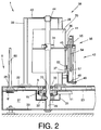
- FIG. 2 shows a side view of the invention Transfer device 1 according to section II-II of FIG. 1.
- the conversion device 1 has one A variety of sheet metal parts assembled chassis 27.
- this chassis 27 28 and 29 are on trunnions
- the transport disks 8 and 9 are rotatably mounted arranged.
- journal 29 is on the one hand in the bottom plate 30 of the chassis 27 and on the other hand via a Assembly member 32 rotatably in an open to the top Recess 31 of the chassis 27 set.
- Assembly member 32 On the journal 29 is further, rotatable via bearing 33, the transport disk 9 stored.
- the transport disc 9 is via a gear 15 and a drive element 11 connected to a drive unit 12.
- a support structure 34 is also on the journal 29 a control link 35 designed in a rotationally fixed manner fixed.
- the control link 35 has an upper control curve 36 and a lower control curve 37.
- the support structure 38 is made from a number of support columns 39, in the present Embodiment three offset by 120 ° Support columns 39, and a cover plate 43 with a Plain bearing 44. About the plain bearing 44 is the Support structure 38 in its upper region rotatable on Supported journal 29. On the support columns 39 are how can be seen, for example, with the aid of FIG Parallelogram guide 40, the base body 41 of the coil and Sleeve handling devices 42 mounted adjustable in height.
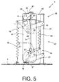
- Figures 4 and 5 each show a coil and Sleeve handling device 42 in detail.
- FIG. 4 shows a rear view of a coil and Sleeve handling device 42.
- the base body 41 of the bobbin and tube handling device 42 is articulated in a vertically pivotable manner on each of the support columns 39, which in turn are fixed on the transport disk 9, via a parallelogram guide 40.
- the control roller 45 is additionally held by the spring element 46 in contact with the control cam 36.
- the base body 41 is also about a pivot axis 47 limited mobility, a two-armed lever 48 arranged.
- a two-armed lever 48 arranged.
- the cranked lever 48 has its end in the direction of Transport disc 9 pointing lever arm 50 over Guide plate 49, which in the pivoting of the lever 48 in Direction S on the sleeve base of the sleeve to be handled (spinning cop or empty sleeve) comes into contact and thereby the sleeve base positioned.
- a control roller 52 is arranged on the lower control curve 37 of the stationary control link 35 is present and is acted upon by a spring element 53.
- a control rod 54 with a pivoted gripper arm 55 of an outer sleeve gripper 56 connected.
- the control rod 54 is connected to the lever 48 via a pivot axis 57 and to the gripper arm 55 of the outer sleeve gripper 56 via a clamping element 61.
- the lever 48 actuated via the control roller 52 is pivoted, the outer sleeve gripper 56 is actuated simultaneously via the control rod 54, so that when the guide plate 49 is positioned on the sleeve base, the gripper arm 55 is simultaneously pivoted about the pivot axis 58 in the direction R and thereby the Presses sleeve tip against a fixed stop 62.
- the spinning machine's own transport pallets 25 are by a in the transport section 4 extending deflector 19 in Direction of the transport disc 8 deflected and by it Driving elements 8 ', 8' 'or 8' '' in the direction of arrow 10, that is towards the transport disk 9, forwarded.
- the same process runs simultaneously in the area of Transport disc 9 from.
- the dishwasher-specific Transport pallets 26 are so by a deflector 20 deflected that the driving elements 9 ', 9' 'or 9' '' of Transport disc 9 capture the transport pallets 26 and correspondingly in the direction of arrow 10 to the transport disk 8 carry on.
- the spinning heads 59 are lifted from the spinning machine-specific transport pallets 25 by the spool and handling devices 42 arranged on the transport disc 8.
- the spinning reels 59 are placed on the opposite transport disc side on the winding machine-specific transport pallets 26, which in turn have been freed from their empty cores 60 by corresponding bobbin and tube handling devices 42 on the transport disc 9.
- the empty sleeves 60 drawn off from the transport pallets 26 by the bobbin and sleeve handling devices 42 of the transport disc 9 are correspondingly deposited on the spinning machine-specific transport pallet 25, which in the meantime is empty and transferred to the region of the transport disc 9 via the deflector element 23. Then the transport pallets 25, which are now equipped with empty sleeves 60, pass over the deflecting element 22, onto the transport path 6 and are discharged in the direction of arrow 7 to the transport system 2 of the ring spinning machine.
- the invention is not restricted to the exemplary embodiment shown. With regard to the structural design of the transfer device, further variants are quite conceivable. It is essential to the invention that the spinning bobbins delivered on spinning machine-specific transport pallets are continuously converted to winding machine-specific transport pallets or that the empty tubes supplied on winding machine-specific transport pallets are continuously converted to the spinning machine-specific transport pallets.
Landscapes
- Replacing, Conveying, And Pick-Finding For Filamentary Materials (AREA)
- Spinning Or Twisting Of Yarns (AREA)
- Warehouses Or Storage Devices (AREA)
Applications Claiming Priority (2)
| Application Number | Priority Date | Filing Date | Title |
|---|---|---|---|
| DE19646337 | 1996-11-09 | ||
| DE19646337A DE19646337A1 (de) | 1996-11-09 | 1996-11-09 | Spulenwechsel- und Transporteinrichtung |
Publications (3)
| Publication Number | Publication Date |
|---|---|
| EP0841278A2 true EP0841278A2 (fr) | 1998-05-13 |
| EP0841278A3 EP0841278A3 (fr) | 1998-09-09 |
| EP0841278B1 EP0841278B1 (fr) | 2001-12-05 |
Family
ID=7811182
Family Applications (1)
| Application Number | Title | Priority Date | Filing Date |
|---|---|---|---|
| EP97113827A Expired - Lifetime EP0841278B1 (fr) | 1996-11-09 | 1997-08-11 | Dispositif de changement et de transport de bobines |
Country Status (5)
| Country | Link |
|---|---|
| US (1) | US5924273A (fr) |
| EP (1) | EP0841278B1 (fr) |
| JP (1) | JP3689230B2 (fr) |
| DE (2) | DE19646337A1 (fr) |
| TR (1) | TR199701312A2 (fr) |
Families Citing this family (5)
| Publication number | Priority date | Publication date | Assignee | Title |
|---|---|---|---|---|
| DE19855126A1 (de) | 1998-11-30 | 2000-05-31 | Schlafhorst & Co W | Kreuzspulautomat sowie Verfahren zum Betreiben eines Kreuzspulautomaten |
| US6595459B2 (en) | 2001-01-30 | 2003-07-22 | Kimberly-Clark Worldwide, Inc. | Apparatus and process for winding webbed material upon cores |
| DE102007039049A1 (de) * | 2007-08-17 | 2009-02-19 | Oerlikon Textile Gmbh & Co. Kg | Spinnanlage |
| DE102008024042A1 (de) | 2008-05-16 | 2009-11-19 | Oerlikon Textile Gmbh & Co. Kg | Spinnkops- und Hülsentransportsystem für eine Kreuzspulen herstellende Textilmaschine |
| EP4015429B1 (fr) * | 2020-12-21 | 2024-06-26 | Savio Macchine Tessili S.p.A. | Dispositif de changement de bobine pour machine de finition telle qu'une machine de bobinage et machine de finition associée |
Family Cites Families (14)
| Publication number | Priority date | Publication date | Assignee | Title |
|---|---|---|---|---|
| DE2727620C3 (de) * | 1977-06-20 | 1979-12-06 | Automation Industrielle S.A., Vouvry (Schweiz) | Vorrichtung zum Transport von Hohlkörpern an einer in einem Gehäuse angeordneten Bearbeitungsstation vorbei |
| IT1202905B (it) * | 1979-03-20 | 1989-02-15 | Sits Soc It Telecom Siemens | Ricevitore di tono per sistemi di telecomunicazioni |
| JPS5859167A (ja) * | 1981-09-25 | 1983-04-08 | Murata Mach Ltd | 管糸搬送システム |
| DE3810785A1 (de) * | 1988-03-30 | 1989-10-12 | Schlafhorst & Co W | Kopstraeger-transportsystem eines spulautomaten |
| DE3813250A1 (de) * | 1988-04-20 | 1989-11-02 | Herlan & Co Maschf | Vorrichtung zum umsetzen von tuben, dosen oder dergl. von einem schrittgeschalteten transportmittel auf ein kontinuierlich laufendes transportmittel |
| DE3919525C2 (de) * | 1989-06-15 | 1998-01-29 | Schlafhorst & Co W | Maschinenverbund zwischen Spinn- und Spulmaschinen |
| US5337551A (en) * | 1989-06-15 | 1994-08-16 | W. Schlafhorst Ag & Co. | Textile machine tube transport assembly with full package and empty tube capability |
| US5179829A (en) * | 1989-06-15 | 1993-01-19 | W. Schlafhorst Ag & Co. | Combined textile yarn spinning and winding system having spinning tube transporting means |
| DE4034824A1 (de) * | 1990-11-02 | 1992-05-07 | Schlafhorst & Co W | Spulenwechsel- und transportsystem fuer huelsen und kopse mit paletten, auf die die kopse und huelsen aufgesetzt sind |
| DE4200798C2 (de) * | 1992-01-15 | 1994-08-18 | Rudolf Zodrow | Flascheninspektionsmaschine |
| DE4207050A1 (de) * | 1992-03-06 | 1993-09-09 | Schurr Stahlecker & Grill | Vorrichtung zum verbinden wenigstens einer spinnmaschine mit wenigstens einer spulmaschine |
| DE4438473A1 (de) * | 1994-10-27 | 1996-05-02 | Zinser Textilmaschinen Gmbh | Verbundsystem zwischen mindestens zwei Textilmaschinen |
| JPH08157144A (ja) * | 1994-11-30 | 1996-06-18 | Toyota Autom Loom Works Ltd | 紡機におけるボビン搬送システム |
| DE4445809C2 (de) * | 1994-12-21 | 1998-01-15 | Zinser Textilmaschinen Gmbh | Vorrichtung zum Umsetzen von Spulen und/oder von Hülsen |
-
1996
- 1996-11-09 DE DE19646337A patent/DE19646337A1/de not_active Withdrawn
-
1997
- 1997-08-11 EP EP97113827A patent/EP0841278B1/fr not_active Expired - Lifetime
- 1997-08-11 DE DE59705657T patent/DE59705657D1/de not_active Expired - Fee Related
- 1997-11-06 TR TR97/01312A patent/TR199701312A2/xx unknown
- 1997-11-06 US US08/965,636 patent/US5924273A/en not_active Expired - Fee Related
- 1997-11-06 JP JP30388897A patent/JP3689230B2/ja not_active Expired - Fee Related
Also Published As
| Publication number | Publication date |
|---|---|
| JPH10139284A (ja) | 1998-05-26 |
| TR199701312A3 (tr) | 1998-05-21 |
| EP0841278A3 (fr) | 1998-09-09 |
| TR199701312A2 (xx) | 1998-05-21 |
| JP3689230B2 (ja) | 2005-08-31 |
| DE19646337A1 (de) | 1998-05-14 |
| EP0841278B1 (fr) | 2001-12-05 |
| DE59705657D1 (de) | 2002-01-17 |
| US5924273A (en) | 1999-07-20 |
Similar Documents
| Publication | Publication Date | Title |
|---|---|---|
| DE3348034C2 (fr) | ||
| DE2402744C2 (de) | Automatische arbeitende Übergabe- und Transportvorrichtung für von einem Förderband angelieferte volle Garnspulen | |
| DE3431790C2 (fr) | ||
| DE3824843C2 (fr) | ||
| EP0274626A1 (fr) | Dispositif de transport de bobines vers ou à partir de métiers à filer ou machines à tordre multiples | |
| DE3630214C3 (de) | Vorrichtung zum selbsttätigen Austausch voller Spulen gegen leere Hülsen an einer Vorspinnmaschine (Flyer-Doffer) | |
| DE3928648A1 (de) | Anlage mit einer oder mehreren spinnmaschinen und mit wenigstens einem wechselwagen zum wechseln von kannen | |
| DE3535219C2 (de) | Vorrichtung zum entfernen von huelsen von ihren traegern | |
| DE19750859A1 (de) | Hülsenmagazin für eine Kreuzspulen herstellende Textilmaschine | |
| DE68925017T2 (de) | Automatisches Ansetzen eines Faserbandes in einer Textilmaschine. | |
| DE3742220C2 (de) | Verfahren und Vorrichtung zum Abtransportieren fertiggewickelter Kreuzspulen | |
| EP0493669B1 (fr) | Dispositif situé entre un métier à retordre et une station d'alimentation de cannettes pour enlever des tubes mis sur supports individuels | |
| DE1901638B2 (de) | Vorrichtung zum automatischen auswechseln voller spulen gegen leere spulenhuelsen fuer ringspinn- und ringzwirnmaschinen | |
| EP0841278B1 (fr) | Dispositif de changement et de transport de bobines | |
| DE3407804C2 (fr) | ||
| DE4402143A1 (de) | Vorrichtung zum Ent- und Versorgen einer Kreuzspulen herstellenden Maschine | |
| CH618939A5 (fr) | ||
| DE19524946B4 (de) | Kreuzspulen herstellende Textilmaschine | |
| DE2842593C2 (de) | Vorrichtung zum Auswechseln von Spulenhülsen auf einer Spinnmaschine | |
| CH667677A5 (de) | Verfahren zum spulenwechsel in einer spinnmaschine. | |
| DE69020250T2 (de) | Vorrichtung zur Übergabe von Spulen in Spinnmaschinen. | |
| EP0916613B1 (fr) | Dispositif pour alimenter en tubes une machine textile pour la production de bobines à spires croisées | |
| EP0525448B1 (fr) | Chariot de transport de pots pour le remplacement automatique de pots | |
| CH685632A5 (de) | Transportfahrzeug für Wattewickel. | |
| DE3832249A1 (de) | Fahrbare vorrichtung zum wechseln von aufgewickelten spulen |
Legal Events
| Date | Code | Title | Description |
|---|---|---|---|
| PUAI | Public reference made under article 153(3) epc to a published international application that has entered the european phase |
Free format text: ORIGINAL CODE: 0009012 |
|
| AK | Designated contracting states |
Kind code of ref document: A2 Designated state(s): BE CH DE ES FR GB IT LI |
|
| PUAL | Search report despatched |
Free format text: ORIGINAL CODE: 0009013 |
|
| AK | Designated contracting states |
Kind code of ref document: A3 Designated state(s): AT BE CH DE DK ES FI FR GB GR IE IT LI LU MC NL PT SE |
|
| 17P | Request for examination filed |
Effective date: 19990309 |
|
| AKX | Designation fees paid |
Free format text: BE CH DE ES FR GB IT LI |
|
| RBV | Designated contracting states (corrected) |
Designated state(s): BE CH DE ES FR GB IT LI |
|
| GRAG | Despatch of communication of intention to grant |
Free format text: ORIGINAL CODE: EPIDOS AGRA |
|
| GRAG | Despatch of communication of intention to grant |
Free format text: ORIGINAL CODE: EPIDOS AGRA |
|
| GRAH | Despatch of communication of intention to grant a patent |
Free format text: ORIGINAL CODE: EPIDOS IGRA |
|
| 17Q | First examination report despatched |
Effective date: 20010219 |
|
| GRAH | Despatch of communication of intention to grant a patent |
Free format text: ORIGINAL CODE: EPIDOS IGRA |
|
| ITF | It: translation for a ep patent filed | ||
| GRAA | (expected) grant |
Free format text: ORIGINAL CODE: 0009210 |
|
| AK | Designated contracting states |
Kind code of ref document: B1 Designated state(s): BE CH DE ES FR GB IT LI |
|
| REG | Reference to a national code |
Ref country code: CH Ref legal event code: EP |
|
| REG | Reference to a national code |
Ref country code: GB Ref legal event code: IF02 |
|
| GBT | Gb: translation of ep patent filed (gb section 77(6)(a)/1977) |
Effective date: 20011207 |
|
| REF | Corresponds to: |
Ref document number: 59705657 Country of ref document: DE Date of ref document: 20020117 |
|
| ET | Fr: translation filed | ||
| PG25 | Lapsed in a contracting state [announced via postgrant information from national office to epo] |
Ref country code: ES Free format text: LAPSE BECAUSE OF FAILURE TO SUBMIT A TRANSLATION OF THE DESCRIPTION OR TO PAY THE FEE WITHIN THE PRESCRIBED TIME-LIMIT Effective date: 20020627 |
|
| PGFP | Annual fee paid to national office [announced via postgrant information from national office to epo] |
Ref country code: BE Payment date: 20020820 Year of fee payment: 6 |
|
| PLBE | No opposition filed within time limit |
Free format text: ORIGINAL CODE: 0009261 |
|
| STAA | Information on the status of an ep patent application or granted ep patent |
Free format text: STATUS: NO OPPOSITION FILED WITHIN TIME LIMIT |
|
| 26N | No opposition filed | ||
| PGFP | Annual fee paid to national office [announced via postgrant information from national office to epo] |
Ref country code: GB Payment date: 20030730 Year of fee payment: 7 |
|
| PG25 | Lapsed in a contracting state [announced via postgrant information from national office to epo] |
Ref country code: BE Free format text: LAPSE BECAUSE OF NON-PAYMENT OF DUE FEES Effective date: 20030831 |
|
| BERE | Be: lapsed |
Owner name: W. *SCHLAFHORST A.G. & CO. Effective date: 20030831 |
|
| PG25 | Lapsed in a contracting state [announced via postgrant information from national office to epo] |
Ref country code: GB Free format text: LAPSE BECAUSE OF NON-PAYMENT OF DUE FEES Effective date: 20040811 |
|
| GBPC | Gb: european patent ceased through non-payment of renewal fee |
Effective date: 20040811 |
|
| PGFP | Annual fee paid to national office [announced via postgrant information from national office to epo] |
Ref country code: FR Payment date: 20050810 Year of fee payment: 9 |
|
| PGFP | Annual fee paid to national office [announced via postgrant information from national office to epo] |
Ref country code: CH Payment date: 20050819 Year of fee payment: 9 |
|
| PG25 | Lapsed in a contracting state [announced via postgrant information from national office to epo] |
Ref country code: LI Free format text: LAPSE BECAUSE OF NON-PAYMENT OF DUE FEES Effective date: 20060831 Ref country code: CH Free format text: LAPSE BECAUSE OF NON-PAYMENT OF DUE FEES Effective date: 20060831 |
|
| REG | Reference to a national code |
Ref country code: CH Ref legal event code: PL |
|
| REG | Reference to a national code |
Ref country code: FR Ref legal event code: ST Effective date: 20070430 |
|
| PG25 | Lapsed in a contracting state [announced via postgrant information from national office to epo] |
Ref country code: FR Free format text: LAPSE BECAUSE OF NON-PAYMENT OF DUE FEES Effective date: 20060831 |
|
| PGFP | Annual fee paid to national office [announced via postgrant information from national office to epo] |
Ref country code: DE Payment date: 20080826 Year of fee payment: 12 |
|
| PG25 | Lapsed in a contracting state [announced via postgrant information from national office to epo] |
Ref country code: DE Free format text: LAPSE BECAUSE OF NON-PAYMENT OF DUE FEES Effective date: 20100302 |
|
| PGFP | Annual fee paid to national office [announced via postgrant information from national office to epo] |
Ref country code: IT Payment date: 20120806 Year of fee payment: 16 |
|
| PG25 | Lapsed in a contracting state [announced via postgrant information from national office to epo] |
Ref country code: IT Free format text: LAPSE BECAUSE OF NON-PAYMENT OF DUE FEES Effective date: 20130811 |