EP0841499A1 - Dispositif de transmission de force d'entraínement - Google Patents
Dispositif de transmission de force d'entraínement Download PDFInfo
- Publication number
- EP0841499A1 EP0841499A1 EP97119470A EP97119470A EP0841499A1 EP 0841499 A1 EP0841499 A1 EP 0841499A1 EP 97119470 A EP97119470 A EP 97119470A EP 97119470 A EP97119470 A EP 97119470A EP 0841499 A1 EP0841499 A1 EP 0841499A1
- Authority
- EP
- European Patent Office
- Prior art keywords
- blades
- housing
- free
- rotary
- transmission apparatus
- Prior art date
- Legal status (The legal status is an assumption and is not a legal conclusion. Google has not performed a legal analysis and makes no representation as to the accuracy of the status listed.)
- Granted
Links
- 230000005540 biological transmission Effects 0.000 title claims abstract description 54
- 239000012530 fluid Substances 0.000 claims abstract description 42
- 230000007246 mechanism Effects 0.000 abstract description 2
- 230000007423 decrease Effects 0.000 description 10
- 230000000694 effects Effects 0.000 description 8
- 230000004044 response Effects 0.000 description 7
- 230000004043 responsiveness Effects 0.000 description 6
- 238000000034 method Methods 0.000 description 4
- 230000009467 reduction Effects 0.000 description 4
- 230000000630 rising effect Effects 0.000 description 4
- 230000009471 action Effects 0.000 description 3
- 230000008859 change Effects 0.000 description 2
- 230000000994 depressogenic effect Effects 0.000 description 2
- 238000011144 upstream manufacturing Methods 0.000 description 2
- 230000003247 decreasing effect Effects 0.000 description 1
- 230000004048 modification Effects 0.000 description 1
- 238000012986 modification Methods 0.000 description 1
Images




Classifications
-
- F—MECHANICAL ENGINEERING; LIGHTING; HEATING; WEAPONS; BLASTING
- F16—ENGINEERING ELEMENTS AND UNITS; GENERAL MEASURES FOR PRODUCING AND MAINTAINING EFFECTIVE FUNCTIONING OF MACHINES OR INSTALLATIONS; THERMAL INSULATION IN GENERAL
- F16D—COUPLINGS FOR TRANSMITTING ROTATION; CLUTCHES; BRAKES
- F16D43/00—Automatic clutches
- F16D43/28—Automatic clutches actuated by fluid pressure
- F16D43/284—Automatic clutches actuated by fluid pressure controlled by angular speed
Definitions
- the present invention relates to a drive force transmission apparatus disposed between two shafts that are rotatable relative to each other and adapted to transmit rotational torque therebetween.
- a drive force transmission apparatus in which a space filled with a viscous fluid is provided on a side of a piston that presses a multiple disc clutch for torque transmission, and blades are rotatably disposed within the space in order to generate a pressure corresponding to a rotational-speed difference between an input shaft and an output shaft.
- the blades rotate relative to the housing and forcibly move the viscous fluid between two surfaces in close proximity to each other in order generate a pressure corresponding to the rotational-speed difference by means of the viscous friction effect of the viscous fluid.
- This pressure acts on the piston so that the multiple disc clutch is brought into a frictional engagement state in order to establish four-wheel drive.
- the response can be improved by a method in which the number of the blades is increased in order to reduce the inter-blade angle, or by a method in which the amount of air mixed into the viscous fluid is reduced to increase the volume ratio between the filled viscous fluid and the space.
- the pressure generated in response to relative rotation decreases, and therefore a required torque cannot be transmitted.
- transmission torque becomes excessively large because of the volume expansion of the viscous fluid stemming from a temperature rise.
- the present invention has been accomplished to solve the above-mentioned problems and a main object of the present invention is to provide a drive force transmission apparatus which has sufficient responsiveness even when the direction of relative rotation reverses.
- ABS antilock braking system
- the present invention provides a drive force transmission apparatus which includes a housing connected to one of two shafts that are rotatable relative to each other; a rotary shaft rotatably supported by the housing and connected to the other shaft; a multiple disc clutch composed of a plurality of outer plates engaged with the housing in the rotational direction and a plurality of inner plates engaged with the rotary shaft in the rotational direction, the multiple disc clutch transmitting rotational torque between the housing and the rotary shaft through frictional engagement between the outer plates and the inner plates; and pressure generation means for generating a pressure corresponding to a rotational-speed difference between the housing and the rotary shaft and for applying the generated force to the multiple disc clutch via a piston, wherein the pressure generating means is composed of a plurality of rotary blades accommodated within a cylindrical space formed between the piston and the housing, the blades arranged in the circumferential direction and rotating together with the rotary shaft; a viscous fluid charged into a plurality of pressure chambers defined by the housing, the
- the drive torque transmission apparatus of the present invention when the direction of relative rotation reverses, the free blade moves relative to the rotary blades, so that the volume of the pressure chamber is decreased and the pressure generated therein is increased.
- This pressure increase compensates a decrease in the internal pressure of the pressure chamber, which decrease would otherwise occur due to behavior of air contained in the viscous fluid when the direction of relative rotation reverses. Accordingly, the drive torque transmission apparatus of the present invention has sufficient responsiveness even when the direction of relative rotation reverses.
- a stepped portion is formed at least at one end of each rotary blade in the rotational direction and one end of the free blade in the rotational direction.
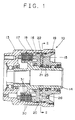
- FIG. 1 shows a drive force transmission apparatus 10 to be disposed between two shafts (front and rear wheel-shafts) that are rotatable relative to each other.
- the drive force transmission apparatus 10 is mainly composed of a front housing 13, a rotary shaft 14 which penetrates the housing 13 and is rotatably supported thereby, pressure generation means 15 for generating a pressure in response to relative rotation between the housing 13 and the rotary shaft 14, a piston 16 to which the pressure generated by the pressure generation means 15 acts, and a multiple disc clutch 17 which is brought into a frictional engagement state by the pressing force imparted by the piston 16.
- One of the above-described two shafts is connected to one end of the housing 13, while the other shaft is inserted into the rotary shaft 14 and spline-engaged therewith.
- a cylindrical hole 18 having a bottom is formed from the other end of the housing 13, and the multiple disc clutch 17 is accommodated within the cylindrical hole 18.
- the piston 16 for pressing the multiple disc clutch 17 is slidably accommodated within the cylindrical hole 18, and the open end of the cylindrical hole 18 is closed by a rear housing 19 screwed into the front housing 13.
- the piston 16 is engaged with a spline formed on the inner circumference of the front housing 13, so that the piston 16 is prevented from rotating relative to the front housing 13.
- a cylindrical space 20 having a limited axial dimension is formed concentrically with the rotary shaft 14.
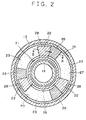
- a rotor 21 Within the cylindrical space 20 is rotatably accommodated a rotor 21, whose center portion is spline-engaged with the outer circumference of the rotary shaft 14.
- the rotor 21 has a plurality of rotary blades 22 which are arranged at constant angular intervals in the circumferential direction and project in the radial direction.
- Each of the rotary blades 22 has a thickness slightly smaller than the axial dimension of the space 20.
- the rotary blades 22 divide the space 20 into a plurality of pressure chambers 23.
- a free rotor 25 is fitted into the rotor 21 concentrically therewith such that the free rotor 25 is allowed to rotate relative to the rotor 21.
- a plurality of free blades 26 are outwardly projected from the free rotor 25.
- the number of the free blades 26 is the same as the number of the rotary blades 22, and the thickness of the free blades 26 is the same as that of the rotary blades 22.
- the free blades 26 can move freely between the rotary blades 22 within the pressure chambers 23.
- the pressure chambers 23 is filled with a viscous fluid 27 at a predetermined filling ratio.
- a small clearance (top clearance) 28 is formed between the distal end of each rotary blade 22 and the inner circumference of the cylindrical space 20, so that the viscous fluid 27 flows restrictedly between the pressure chambers located on opposite sides of each rotary blade 22 in the circumferential direction.
- the clearance 28 may be formed as a side clearance on either axial side of each rotary blade 22.
- the flow of the viscous fluid 27 through the clearance 28 allows the free blades 26 to move relative to the rotary blades 22, so that the volumes of the pressure chambers 23 between the rotary blades 22 and the free blades 26 changes with relative movement therebetween.
- the above-described rotary blades 22, the free blades 26, and the viscous fluid 27, all accommodated within the space 20, constitute the above-described pressure generation means 15.
- the multiple disc clutch 17 accommodated within the cylindrical hole 18 is composed of a plurality of outer plates (separate plates) 30 and a plurality of inner plates (friction plates) 31, which are disposed alternately in the axial direction.
- the outer circumferences of the outer plates 30 are in spline-engagement with the inner circumferential surface of the housing 13, while the inner circumferences of the inner plates 31 are in spline-engagement with the outer circumferential surface of the rotary shaft 14.
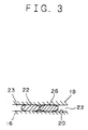
- the free blades 26 are rotated in the rotational direction of the rotary shaft 14 by the rotary blades 22, so that the free blades 26 rotate together with the rotary blades 22, as shown in FIGS. 2 and 3.
- the plurality of outer plates 30 and the plurality of inner plates 31 of the multiple disc clutch 17 are frictionally engaged with each other with a pressing force corresponding to the pressure acting on the piston 16, so that torque is transmitted between the housing 13 and the rotary shaft 14, i.e., between the front and rear wheel-shafts, via the multiple disc clutch 17. In this way, the vehicle is brought into a four-wheel drive state.
- the drive force transmission apparatus returns to the ordinary state in which an internal pressure proportional to the rotational-speed difference is generated within each pressure chamber 23 due to the viscous friction effect of the viscous fluid 27 caused by the relative rotation between the housing 13 and the rotary shaft 14.
- a drive force transmission apparatus according to a second embodiment of the present invention will be described with reference to FIG. 6.
- a plurality of independent or separated free blades 126 are movably disposed in the pressure chambers 23 between the rotary blades 22. Specifically, the inner end of each free blade 126 is guided by the outer circumferential surface of the rotor 21 and the outer end of each free blade 126 is guided by the inner circumferential surface of the cylindrical space 20 for free sliding movement within the corresponding pressure chamber 23.
- the drive force transmission apparatus operates in the same way as that of the first embodiment. In this case, if a circular plate is used as the free blade 126, the sliding resistance of the free blades 126 can be reduced.
- the front housing 13, the multiple disc clutch 17, the piston 16, the space 20, and the rear housing 19 are arranged in this sequence in the drive force transmission apparatus.
- the reversed arrange may be employed. That is, the drive force transmission apparatus may be constructed such that the front housing 13, the space 20, the piston 16, the multiple disc clutch 17, and the rear housing 19 are disposed in this sequence.
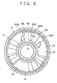
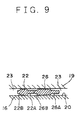
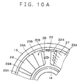
- a drive force transmission apparatus will be described with reference to FIGS. 7 - 11.
- the drive force transmission apparatus of the present embodiment is substantially the same as that of the first embodiment except that each of the rotary blades 22 and the free blades 26 has a stepped portion (i.e., thin-thickness portions) at either end thereof in the rotational direction. Since the basic structure of the drive force transmission apparatus of the present embodiment is the same as that of the first embodiment, components identical to those in the first embodiment are denoted by the same reference numerals and descriptions therefor will be omitted.
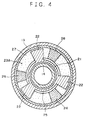
- stepped portions 22A and 22B each having a smaller thickness are formed at opposite ends of each rotary blade 22 in the rotational direction, and stepped portions 26A and 26B each having a smaller thickness are formed at opposite ends of each free blade 26 in the rotational direction.
- the stepped portions 22A and 22B of the rotary blades 22 are formed asymmetrically such that the stepped portions 22A located on the forward-rotation side of the rotary blades 22 have a larger dimension in the rotational direction than do the stepped portions 22B located on the reverse-rotation side thereof.
- the stepped portions 26A and 26B of the free blades 26 are formed asymmetrically such that the stepped portions 26A located on the forward-rotation side of the free blades 26 have a larger dimension in the rotational direction than do the stepped portions 22B located on the reverse-rotation side thereof.
- the free blades 26 are rotated in the rotational direction of the rotary shaft 14 by the rotary blades 22, so that the free blades 26 rotate together with the rotary blades 22, as shown in FIGS. 8 and 9.
- the plurality of outer plates 30 and the plurality of inner plates 31 of the multiple disc clutch 17 are frictionally engaged with each other with a pressing force corresponding to the pressure acting on the piston 16, so that torque is transmitted between the housing 13 and the rotary shaft 14, i.e., between the front and rear wheel-shafts, via the multiple disc clutch 17. In this way, the vehicle is brought into a four-wheel drive state.
- ABS antilock braking system
- the viscous fluid 27 flows from one pressure chamber 23A to the other pressure chamber 23B along the longer stepped potion 22A of each rotary blade 22 and via the corresponding clearance 28. Therefore, the action of the free blades 26 for increasing the pressures generated within the pressure chambers 23 is enhanced.
- the drive force transmission apparatus returns to the ordinary state in which an internal pressure proportional to the rotational-speed difference is generated within each pressure chamber 23 due to the viscous friction effect of the viscous fluid 27 caused by the relative rotation between the housing 13 and the rotary shaft 14.
- stepped portions 22A and 22B having different lengths in the rotational direction are formed on the circumferentially opposite ends of each rotary blade 22, and the stepped portions 26A and 26B having different lengths in the rotational direction are formed on the circumferentially opposite ends of each free blade 26, an increase in the pressure generated in the pressure chamber 23 during the reversed relative ration can be suppressed. Accordingly, the compatibility of the drive force transmission apparatus with the ABS can be improved.
- the front housing 13, the multiple disc clutch 17, the piston 16, the space 20, and the rear housing 19 are arranged in this sequence in the drive force transmission apparatus.
- the reversed arrange may be employed. That is, the drive force transmission apparatus may be constructed such that the front housing 13, the space 20, the piston 16, the multiple disc clutch 17, and the rear housing 19 are disposed in this sequence.
- the plurality of separated and independent free blades 26 are disposed in the pressure chambers 23.
- the structure of the present embodiment may be modified such that a free rotor 25 is rotatably fitted into the rotor 21 concentrically therewith, and the plurality of free blades 26 are projected from the free rotor 25 at constant angular intervals in the circumferential direction.
- the stepped portions 22A and 22B having different lengths in the rotational direction are formed on the circumferentially opposite ends of each rotary blade 22, and the stepped portions 26A and 26B having different lengths in the rotational direction are formed on the circumferentially opposite ends of each free blade 26.
- the shorter stepped portions 22B and 26B may be omitted.
- a drive force transmission apparatus includes a housing (13) connected to one of two shafts that are rotatable relative to each other, a rotary shaft (14) rotatably supported by the housing and connected to the other shaft, and a multiple disc clutch (17) composed of a plurality of outer plates (30) engaged with the housing (13) in the rotational direction and a plurality of inner plates (31) engaged with the rotary shaft (14) in the rotational direction.
- the multiple disc clutch (17) transmits rotational torque between the housing (13) and the rotary shaft (14) through frictional engagement between the outer plates (30) and the inner plates (31).
- the apparatus also includes a pressure generation mechanism (15) for generating a pressure corresponding to a rotational-speed difference between the housing (13) and the rotary shaft (14) and for applying the generated force to the multiple disc clutch (17) via a piston (16).
- the pressure generating means (15) is composed of a plurality of rotary blades (22) accommodated within a cylindrical space (20) formed between the piston (16) and the housing (13) and rotating together with the rotary shaft (14), a viscous fluid (27) charged into a plurality of pressure chambers (23) defined by the housing (13), the piston (16), and the rotary blades (22), and a free blade (26) accommodated within at least one pressure chamber (23).
- the free blade (26) is freely movable in the circumferential direction between the rotary blades (22).
Landscapes
- Engineering & Computer Science (AREA)
- General Engineering & Computer Science (AREA)
- Physics & Mathematics (AREA)
- Fluid Mechanics (AREA)
- Mechanical Engineering (AREA)
- Arrangement And Driving Of Transmission Devices (AREA)
Applications Claiming Priority (6)
| Application Number | Priority Date | Filing Date | Title |
|---|---|---|---|
| JP29546796 | 1996-11-07 | ||
| JP295467/96 | 1996-11-07 | ||
| JP8295467A JP2993892B2 (ja) | 1996-11-07 | 1996-11-07 | 駆動力伝達装置 |
| JP29556796 | 1996-11-08 | ||
| JP295567/96 | 1996-11-08 | ||
| JP29556796A JP3321373B2 (ja) | 1996-11-08 | 1996-11-08 | 駆動力伝達装置 |
Publications (2)
| Publication Number | Publication Date |
|---|---|
| EP0841499A1 true EP0841499A1 (fr) | 1998-05-13 |
| EP0841499B1 EP0841499B1 (fr) | 2000-09-06 |
Family
ID=26560291
Family Applications (1)
| Application Number | Title | Priority Date | Filing Date |
|---|---|---|---|
| EP97119470A Expired - Lifetime EP0841499B1 (fr) | 1996-11-07 | 1997-11-06 | Dispositif de transmission de force d'entraínement |
Country Status (3)
| Country | Link |
|---|---|
| US (1) | US5899306A (fr) |
| EP (1) | EP0841499B1 (fr) |
| DE (1) | DE69703017T2 (fr) |
Families Citing this family (2)
| Publication number | Priority date | Publication date | Assignee | Title |
|---|---|---|---|---|
| US8348802B2 (en) * | 2009-04-30 | 2013-01-08 | Ford Global Technologies, Llc | Transmission clutch assembly |
| JP5668398B2 (ja) | 2010-08-30 | 2015-02-12 | 株式会社ジェイテクト | 駆動力伝達装置及び車両 |
Citations (3)
| Publication number | Priority date | Publication date | Assignee | Title |
|---|---|---|---|---|
| US4905808A (en) * | 1987-03-27 | 1990-03-06 | Toyoda Koki Kabushiki Kaisha | Torque transmission device for a four-wheel drive vehicle |
| JPH02120529A (ja) * | 1988-10-31 | 1990-05-08 | Toyoda Mach Works Ltd | 駆動力伝達装置 |
| JPH0735171A (ja) * | 1993-06-25 | 1995-02-03 | Toyoda Mach Works Ltd | 駆動力伝達装置 |
Family Cites Families (8)
| Publication number | Priority date | Publication date | Assignee | Title |
|---|---|---|---|---|
| JPS646526A (en) * | 1987-03-30 | 1989-01-11 | Toyoda Machine Works Ltd | Drive force transmitting device |
| JP2669650B2 (ja) * | 1988-07-07 | 1997-10-29 | 豊田工機株式会社 | 駆動力伝達装置 |
| JPH02203026A (ja) * | 1989-02-01 | 1990-08-13 | Toyoda Mach Works Ltd | 駆動力伝達装置 |
| JP2796417B2 (ja) * | 1990-10-11 | 1998-09-10 | 豊田工機株式会社 | 駆動力伝達装置 |
| JPH04231730A (ja) * | 1990-12-27 | 1992-08-20 | Toyoda Mach Works Ltd | 駆動力伝達装置 |
| DE4406071A1 (de) * | 1993-02-24 | 1994-09-29 | Toyoda Machine Works Ltd | Drehkraft-Kupplung |
| DE4345484C2 (de) * | 1993-08-17 | 2001-01-11 | Gkn Viscodrive Gmbh | Vorrichtung zur Steuerung einer Viscokupplung |
| DE19505800C2 (de) * | 1995-02-21 | 1998-10-15 | Gkn Viscodrive Gmbh | Vorrichtung zur Steuerung einer Kupplung |
-
1997
- 1997-11-06 EP EP97119470A patent/EP0841499B1/fr not_active Expired - Lifetime
- 1997-11-06 DE DE69703017T patent/DE69703017T2/de not_active Expired - Lifetime
- 1997-11-07 US US08/966,244 patent/US5899306A/en not_active Expired - Lifetime
Patent Citations (3)
| Publication number | Priority date | Publication date | Assignee | Title |
|---|---|---|---|---|
| US4905808A (en) * | 1987-03-27 | 1990-03-06 | Toyoda Koki Kabushiki Kaisha | Torque transmission device for a four-wheel drive vehicle |
| JPH02120529A (ja) * | 1988-10-31 | 1990-05-08 | Toyoda Mach Works Ltd | 駆動力伝達装置 |
| JPH0735171A (ja) * | 1993-06-25 | 1995-02-03 | Toyoda Mach Works Ltd | 駆動力伝達装置 |
Non-Patent Citations (2)
| Title |
|---|
| PATENT ABSTRACTS OF JAPAN vol. 014, no. 347 (M - 1002) 26 July 1990 (1990-07-26) * |
| PATENT ABSTRACTS OF JAPAN vol. 095, no. 005 30 June 1995 (1995-06-30) * |
Also Published As
| Publication number | Publication date |
|---|---|
| DE69703017D1 (de) | 2000-10-12 |
| EP0841499B1 (fr) | 2000-09-06 |
| DE69703017T2 (de) | 2001-05-03 |
| US5899306A (en) | 1999-05-04 |
Similar Documents
| Publication | Publication Date | Title |
|---|---|---|
| AU628829B2 (en) | Driving power transmission device | |
| EP0381505B1 (fr) | Embrayage de contrôle pour transmission de moment de rotation | |
| US5178249A (en) | Rotary coupling for torque transmission | |
| US5899306A (en) | Drive force transmission apparatus | |
| JP3321373B2 (ja) | 駆動力伝達装置 | |
| JP3192031B2 (ja) | 駆動力伝達装置 | |
| JP2865455B2 (ja) | 駆動力伝達装置 | |
| JP2993892B2 (ja) | 駆動力伝達装置 | |
| JP3070206B2 (ja) | 駆動力伝達装置 | |
| JPH0560154A (ja) | 駆動力伝達装置 | |
| JP2522810B2 (ja) | 駆動力伝達装置 | |
| JPH0533819A (ja) | 駆動力伝達装置 | |
| JP2661217B2 (ja) | 動力伝達機構 | |
| JP2831089B2 (ja) | 駆動力伝達装置 | |
| JPH0730998Y2 (ja) | 動力伝達機構 | |
| JPH0575529U (ja) | 駆動力伝達装置 | |
| JPH0425625A (ja) | 駆動力伝達装置 | |
| JPH048926A (ja) | 駆動力伝達装置 | |
| JPH0519678U (ja) | 駆動力伝達装置 | |
| JPH06249269A (ja) | 駆動力伝達装置 | |
| JPH07208509A (ja) | 駆動力伝達装置 | |
| JPH07132747A (ja) | 駆動力伝達装置 | |
| JPH03265723A (ja) | 駆動力伝達装置 | |
| JPH01182635A (ja) | 駆動力伝達装置 | |
| JPH06280904A (ja) | 駆動力伝達装置 |
Legal Events
| Date | Code | Title | Description |
|---|---|---|---|
| PUAI | Public reference made under article 153(3) epc to a published international application that has entered the european phase |
Free format text: ORIGINAL CODE: 0009012 |
|
| AK | Designated contracting states |
Kind code of ref document: A1 Designated state(s): DE FR GB |
|
| AX | Request for extension of the european patent |
Free format text: AL;LT;LV;MK;RO;SI |
|
| 17P | Request for examination filed |
Effective date: 19981009 |
|
| AKX | Designation fees paid |
Free format text: DE FR GB |
|
| RBV | Designated contracting states (corrected) |
Designated state(s): DE FR GB |
|
| 17Q | First examination report despatched |
Effective date: 19990125 |
|
| GRAG | Despatch of communication of intention to grant |
Free format text: ORIGINAL CODE: EPIDOS AGRA |
|
| GRAG | Despatch of communication of intention to grant |
Free format text: ORIGINAL CODE: EPIDOS AGRA |
|
| GRAH | Despatch of communication of intention to grant a patent |
Free format text: ORIGINAL CODE: EPIDOS IGRA |
|
| GRAH | Despatch of communication of intention to grant a patent |
Free format text: ORIGINAL CODE: EPIDOS IGRA |
|
| GRAA | (expected) grant |
Free format text: ORIGINAL CODE: 0009210 |
|
| AK | Designated contracting states |
Kind code of ref document: B1 Designated state(s): DE FR GB |
|
| PG25 | Lapsed in a contracting state [announced via postgrant information from national office to epo] |
Ref country code: FR Free format text: LAPSE BECAUSE OF FAILURE TO SUBMIT A TRANSLATION OF THE DESCRIPTION OR TO PAY THE FEE WITHIN THE PRESCRIBED TIME-LIMIT Effective date: 20000906 |
|
| REF | Corresponds to: |
Ref document number: 69703017 Country of ref document: DE Date of ref document: 20001012 |
|
| PGFP | Annual fee paid to national office [announced via postgrant information from national office to epo] |
Ref country code: FR Payment date: 20001110 Year of fee payment: 4 |
|
| EN | Fr: translation not filed | ||
| PLBE | No opposition filed within time limit |
Free format text: ORIGINAL CODE: 0009261 |
|
| STAA | Information on the status of an ep patent application or granted ep patent |
Free format text: STATUS: NO OPPOSITION FILED WITHIN TIME LIMIT |
|
| 26N | No opposition filed | ||
| REG | Reference to a national code |
Ref country code: GB Ref legal event code: IF02 |
|
| PGFP | Annual fee paid to national office [announced via postgrant information from national office to epo] |
Ref country code: DE Payment date: 20121031 Year of fee payment: 16 |
|
| PGFP | Annual fee paid to national office [announced via postgrant information from national office to epo] |
Ref country code: GB Payment date: 20121031 Year of fee payment: 16 |
|
| GBPC | Gb: european patent ceased through non-payment of renewal fee |
Effective date: 20131106 |
|
| REG | Reference to a national code |
Ref country code: DE Ref legal event code: R119 Ref document number: 69703017 Country of ref document: DE Effective date: 20140603 |
|
| PG25 | Lapsed in a contracting state [announced via postgrant information from national office to epo] |
Ref country code: DE Free format text: LAPSE BECAUSE OF NON-PAYMENT OF DUE FEES Effective date: 20140603 |
|
| PG25 | Lapsed in a contracting state [announced via postgrant information from national office to epo] |
Ref country code: GB Free format text: LAPSE BECAUSE OF NON-PAYMENT OF DUE FEES Effective date: 20131106 |