EP0841562B1 - Utilisation d'un capteur pour mesurer la concentration d'oxyde d'azote - Google Patents
Utilisation d'un capteur pour mesurer la concentration d'oxyde d'azote Download PDFInfo
- Publication number
- EP0841562B1 EP0841562B1 EP97119646A EP97119646A EP0841562B1 EP 0841562 B1 EP0841562 B1 EP 0841562B1 EP 97119646 A EP97119646 A EP 97119646A EP 97119646 A EP97119646 A EP 97119646A EP 0841562 B1 EP0841562 B1 EP 0841562B1
- Authority
- EP
- European Patent Office
- Prior art keywords
- cell
- measurement
- oxygen
- oxygen concentration
- current
- Prior art date
- Legal status (The legal status is an assumption and is not a legal conclusion. Google has not performed a legal analysis and makes no representation as to the accuracy of the status listed.)
- Expired - Lifetime
Links
Images




Classifications
-
- G—PHYSICS
- G01—MEASURING; TESTING
- G01N—INVESTIGATING OR ANALYSING MATERIALS BY DETERMINING THEIR CHEMICAL OR PHYSICAL PROPERTIES
- G01N27/00—Investigating or analysing materials by the use of electric, electrochemical, or magnetic means
- G01N27/26—Investigating or analysing materials by the use of electric, electrochemical, or magnetic means by investigating electrochemical variables; by using electrolysis or electrophoresis
- G01N27/416—Systems
- G01N27/417—Systems using cells, i.e. more than one cell and probes with solid electrolytes
-
- G—PHYSICS
- G01—MEASURING; TESTING
- G01N—INVESTIGATING OR ANALYSING MATERIALS BY DETERMINING THEIR CHEMICAL OR PHYSICAL PROPERTIES
- G01N27/00—Investigating or analysing materials by the use of electric, electrochemical, or magnetic means
- G01N27/26—Investigating or analysing materials by the use of electric, electrochemical, or magnetic means by investigating electrochemical variables; by using electrolysis or electrophoresis
- G01N27/403—Cells and electrode assemblies
- G01N27/406—Cells and probes with solid electrolytes
- G01N27/407—Cells and probes with solid electrolytes for investigating or analysing gases
- G01N27/4073—Composition or fabrication of the solid electrolyte
- G01N27/4074—Composition or fabrication of the solid electrolyte for detection of gases other than oxygen
Definitions
- This invention relates with respect to its technical field, to a method and apparatus for measuring the oxygen concentration and the nitrogen oxide concentration using an NOx sensor and is preferably designed for detecting the concentration of nitrogen oxides as toxious components exhausted from a variety of combustion equipment, such as internal combustion engines.
- a nitrogen oxide concentration measurement device for measuring the concentration of nitrogen oxides (NOx) in exhaust gases of, for example, internal combustion engines, using an NOx sensor in which, as disclosed for example in European publication EP 0678740A1, and SAE paper No.960334 pages 137 to 142, 1996, etc., a first measurement chamber communicating with a measured gas side via first diffusion rate-regulating layer and a second measurement chamber communicating with this first measurement chamber via a second diffusion rate regulating layer are formed of oxygen ion conductive solid electrolyte layers, a first oxygen pumping cell and an oxygen concentration measurement cell are formed on the first measurement chamber by each sandwiching a solid electrolyte layer by a pair of porous electrodes, and in which a second oxygen pumping cell is formed on the second measurement chamber similarly by sandwiching a solid electrolyte layer by another pair of porous electrodes.
- the current is caused to flow across the first oxygen pumping cell so that an output voltage from the oxygen concentration measurement cell will be a pre-set constant value for applying a pre-set constant voltage across the second oxygen pumping cell while maintaining a constant oxygen concentration in the first measurement chamber for pumping out oxygen from the second measurement chamber by applying a constant voltage across the second oxygen pumping cell.
- the NOx concentration in the gas under measurement is detected based on the current value flowing in the second oxygen pumping cell.
- gas components other than NOx that is oxygen, carbon monoxide or carbon dioxide
- the inside of the first measurement chamber is controlled by the first oxygen pumping cell to an extremely low oxygen concentration, while a constant voltage is applied across the second oxygen pumping cell in a direction of pumping out oxygen from the second measurement chamber, on the side of the second measurement chamber into which flows the gas controlled to the low oxygen concentration, thereby decomposing NOx in the gas under measurement into oxygen and nitrogen by the catalytic function of the porous electrode constituting the second oxygen pumping cell and extracting oxygen from the second measurement chamber.
- the pump current flowing at this time through the second oxygen pumping cell is detected in an attempt for measuring the NOx concentration in the gas under measurement without being affected by the other gas components in the gas under measurement.
- each cell needs to be activated by heating the sensor to a pre-set activation temperature, such as 800°C or higher.
- a separate heater is provided for heating the sensor.
- the above-described nitrogen oxide concentration measurement device for instance, for monitoring the state of the NOx catalyst which reduces NOx for suppressing NOx in an internal combustion engine driven at a lean air/fuel ratio, that is with an air/fuel ratio having a proportion of air larger than fuel, thus increasing the NOx component in the exhaust gases, i.e., a so-called lean-burn engine.
- the above-described nitrogen oxide concentration measurement device is used for performing such control in which an NOx sensor is loaded downstream of the NOx catalyst in an exhaust path of the internal combustion engine to measure the NOx concentration for detecting the amount of leakage of NOx from the NOx catalyst.
- an NOx sensor is loaded downstream of the NOx catalyst in an exhaust path of the internal combustion engine to measure the NOx concentration for detecting the amount of leakage of NOx from the NOx catalyst.
- the air/fuel ratio of the air/fuel mixture supplied to the internal combustion engine is transiently controlled to a fuel-rich air/fuel ratio for discharging unburned gas from a internal combustion engine, with the unburned gas being reacted with NOx accumulated in the NOx catalyst for suppressing emission of NOx.
- a separate air/fuel ratio measurement device for measuring the air/fuel ratio based on the oxygen concentration in the exhaust gas needs to be provided in the internal combustion engine, because the above-mentioned nitrogen oxide concentration measurement device cannot measure the air/fuel ratio of the air/fuel mixture supplied to the internal combustion engine.
- the air/fuel mixture control commonly carried out in the internal combust ion engine in the conventional practice needs to be executed simultaneously.
- an NOx sensor and an oxygen concentration sensor (so-called air/fuel ratio sensor) need to be provided in the exhaust gas system of the internal combustion engine.
- EP678740 discloses a method of measuring concentration of a gas component using a sensor comprising a first chamber having an electrochemical oxygen pumping cell with a pair of electrodes and an oxygen concentration measuring cell with a pair of electrodes for a first internal space.
- a second internal space having a porous measuring electrode of a second pumping cell, and an ammeter to detect the pumping current which is proportional to the concentration of decomposed NOx in the second space is also provided.
- the oxygen concentration and the nitrogen oxide concentration in a gas under measurement are measured using an NOx sensor having a first measurement chamber, a second measurement chamber and a heater.
- the first measurement chamber has preferably a first oxygen pumping cell and an oxygen concentration measuring cell and communicates with the side of the gas under measurement of a first diffusion rate regulating layer.
- the gas in the first or second chamber might also be called gas under measurement.
- the term "the side of” is intended to represent the gas under measurement, e.g. straight exhaust gas itself before entering the first chamber.
- the first oxygen pumping cell has advantageously an oxygen ion conductive solid electrolyte layer sandwiched between porous electrodes.
- the second measurement chamber has a second oxygen pumping cell preferably having an oxygen ion conductive solid electrolyte layer sandwiched between porous electrodes, and advantageously communicates with the first measurement chamber via a second diffusion rate regulating layer.
- the heater is adapted for heating the cells to a pre-set activation temperature.
- the method includes at least one of the following steps-the step of causing the current to flow in the first oxygen pumping cell so that an output voltage of the oxygen concentration measurement cell will be of a pre-set value for controlling the oxygen concentration in the first measurement chamber to a constant value, the step of applying a constant voltage across the second oxygen pumping cell in a direction of pumping out oxygen out of the first measurement chamber, and the step of measuring the concentration of nitrogen oxide in the gas under measurement based on the value of the current flowing in the second oxygen pumping cell and measuring the oxygen concentration in the gas under measurement based on the value of the current flowing in the first oxygen pumping cell.
- the amount of the current supplied to the heater is controlled so that the temperature of the oxygen concentration measurement cell in the NOx sensor will be a pre-set target temperature.
- the measured results of the oxygen concentration and the nitrogen oxide concentration are corrected depending on the deviation from the target value of the temperature of the oxygen concentration measurement cell for compensating the measured results for temperature.
- a device for measuring the oxygen concentration and the nitrogen oxide concentration in a gas under measurement using an NOx sensor similar to the NOx sensor stated in the first aspect.
- the measurement device includes pump current control means which could be a circuit or module for causing the current to flow in the first oxygen pumping cell so that an output voltage of the oxygen concentration measurement cell will be of a pre-set value for controlling the oxygen concentration in the first measurement chamber to a constant value, and advantageously constant voltage application means which could be a circuit or module for applying a constant voltage across the second oxygen pumping cell in a direction of pumping out oxygen out of the second measurement chamber.
- the measurement device may further comprise nitrogen oxide concentration measurement means which could be a determining circuit or module for measuring the concentration of nitrogen oxide in the gas under measurement based on the value of the current flowing in the second oxygen pumping cell, and advantageously oxygen concentration measurement means, which could be a determining circuit or module) for measuring the oxygen concentration in the gas under measurement based on the value of the current flowing in the first oxygen pumping cell.
- nitrogen oxide concentration measurement means which could be a determining circuit or module for measuring the concentration of nitrogen oxide in the gas under measurement based on the value of the current flowing in the second oxygen pumping cell
- oxygen concentration measurement means which could be a determining circuit or module
- the device may further include temperature detection means which could be a determining circuit or module for detecting the temperature of the oxygen concentration measurement cell and/or heater current supplying controlling means for controlling the current supplied to the heater so that the temperature of the oxygen concentration measurement cell as detected by the temperature detection means will be a pre-set target temperature.
- temperature detection means which could be a determining circuit or module for detecting the temperature of the oxygen concentration measurement cell and/or heater current supplying controlling means for controlling the current supplied to the heater so that the temperature of the oxygen concentration measurement cell as detected by the temperature detection means will be a pre-set target temperature.
- the device may further include correction means which could be a circuit or module for temperature-compensating results of measurement of the oxygen concentration and the nitrogen oxide concentration by correcting the results of measurement responsive to deviation from the target temperature of the temperature of the oxygen concentration measurement cell as detected by the temperature detection means.
- correction means could be a circuit or module for temperature-compensating results of measurement of the oxygen concentration and the nitrogen oxide concentration by correcting the results of measurement responsive to deviation from the target temperature of the temperature of the oxygen concentration measurement cell as detected by the temperature detection means.
- the temperature detection means detects the temperature of the oxygen concentration measurement cell by detecting the internal resistance of the measurement cell and wherein especially the heater current supply controlling means controls the amount of the current supplied to the heater so that the detected internal resistance of the oxygen concentration measurement cell will be of a pre-set value corresponding to the target temperature.
- the porous electrode on the opposite side of the oxygen concentration measurement cell with respect to the first measurement chamber is preferably closed and part of oxygen in the resulting closed space can be leaked out via a leakage resistance, wherein advantageously the pump current control means causes a small amount of current to flow in the oxygen concentration measurement cell in a direction of pumping out oxygen in the first measurement space into the closed space to control the amount of current flowing in the first oxygen pumping cell.
- the closed space is caused to function as an internal oxygen reference source, an electromotive force generated across the oxygen concentration measurement cell will be of a constant value.
- the temperature detection means preferably periodically interrupts connection between the pump current control means and the oxygen concentration measurement cell so that, during such interruption, an amount of current for detecting the internal resistance larger than the small current is caused to flow in the oxygen concentration measurement cell in an opposite direction to the flowing direction of the small current.
- the internal resistance of the oxygen concentration measurement cell may be detected from a voltage generated at this time across the electrodes of the oxygen concentration measurement cell.
- the temperature detection means causes the current for detecting the internal resistance to flow in the oxygen concentration measurement cell in one direction, the temperature detection means then causing the current to flow in an opposite direction to the preceding direction of the internal resistance detecting current.
- the first oxygen pumping cell, oxygen concentration measurement cell and the second oxygen pumping cells are preferably formed of solid electrolyte layers as different thin plates, whereby the first measurement chamber and the second measurement chamber are made up by laminating the respective solid electrolyte layers each with a small gap in-between with the solid electrolyte layers constituting the first and second oxygen pumping cells facing outwards.
- the heater advantageously includes two heater substrates in the form of thin plates being made up of heater substrates with heater wiring embedded therein, the heater substrates being arranged on both sides in the laminating direction of each solid electrolyte layer in the NOx sensor with a pre-set interval in-between for heating the NOx sensor, and wherein suitably the first diffusion layer is arranged in the solid electrolyte layer constituting the first oxygen pumping cell so that the first diffusion layer is disposed at a position opposing a mid position of the heater wiring in the heater substrate.
- the second diffusion rate regulating layer may overlap at least a portion of the first diffusion rate regulating layer in a view where the NOx sensor is projected from the laminating direction of solid electrolyte layers, and wherein the oxygen concentration measurement cell is advantageously provided in the vicinity of the second diffusion rate regulating layer.
- the current is caused to flow in a first oxygen pumping cell so that an output voltage of an oxygen concentration measurement cell in the Nox sensor will be constant thereby controlling the oxygen conentration in the first measurement chamber constant, whilst a constant voltage is applied across the second oxygen pumping cell in a direction of pumping out oxygen from the second measurement cell.
- the NOx sensor is driven in the same driving direction as that for measuring the NOx concentration using a NOx sensor. At this time, not only is the nitrogen oxide concentration (NOx concentration) measured from the current value flowing in the second oxygen pumping cell, but also is the oxygen concentration in the gas under measurement measured from the current value flowing in the first oxygen pumping cell.
- the pump current control by controlling the current flowing in the first pumping cell to control the oxygen concentration in the first measurement chamber to a constant value is similar to the operation of measuring the oxygen concentration in the gas under measurement using a universal-range air/fuel mixture sensor having a pumping cell and an oxygen concentration measurement cell in/on a measurement chamber having a limited diffusion of the gas under measurement, such that the current flowing through the first pumping cell is proportionate to the oxygen concentration in the gas under measurement and the oxygen concentration can be measured (derived) from the current value.
- the oxygen concentration and the NOx concentration are measured using only the NOx sensor, there is no necessity of providing two sensors, namely an NOx sensor and an air/fuel ratio sensor, in an exhaust gas system of an internal combustion engine, thus simplifying the structure of the control device for reducing the cost.
- the oxygen concentration and the NOx concentration are measured using the sole NOx sensor, the measured results exhibit high correlation as compared to a case where the concentrations are measured using different sensors, that is an oxygen sensor and an NOx sensor.
- the oxygen concentration and the NOx concentration as measured by the inventive method are used, it becomes possible to judge deterioration of the NOx catalyst provided in an exhaust gas pipe of the internal combustion engine with high accuracy.
- the allowable value of the amount of leakage of NOx corresponding to the measured oxygen concentration in other words, the air/fuel ratio
- the measured value of the NOx concentration is checked as to whether or not it is lower than the allowable value and the NOx catalyst is judged to be deteriorated if the measured value of the NOx concentration is in excess of the allowable value.
- the current supplied to the heater provided in the NOx sensor is controlled so that the temperature of the oxygen concentration measurement cell in the NOx sensor will be a pre-set target temperature.
- the oxygen concentration in the first measurement chamber can be controlled to be constant by current supply control to the first oxygen pumping cell (pump current control), the oxygen concentration cannot be measured correctly, such that, for controlling the oxygen concentration in the first measurement chamber to be constant, it is necessary to hold a constant temperature in the oxygen concentration measurement cell designed to measure the oxygen concentration.
- the electromotive force EMF in the oxygen concentration measurement cell is 200 mV
- the electromotive force EMF is 160 mV for a temperature T of 800°K.
- the inside of the measurement chamber is controlled by the pump current control so as to be substantially (almost) depleted of oxygen (the state of zero oxygen concentration), it is possible to obtain rather stable temperature characteristics.
- the NOx sensor if the inside of the measurement chamber is controlled by the pump current control so as to be substantially depleted of oxygen (the state of zero oxygen concentration), the NOx component in the gas under measurement flowing into the first measurement chamber is decomposed offering a high risk that the NOx concentration (in the gas under measurement) cannot be measured.
- control is made so that a minor amount of oxygen (corresponding to, for example, a low oxygen concentration of 1000 ppm) is left in the first measurement chamber.
- a minor amount of oxygen corresponding to, for example, a low oxygen concentration of 1000 ppm
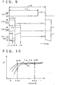
- Fig.10 shows the relation between the output voltage Vs of an oxygen concentration measurement cell and the pump current Ip flowing in an oxygen pumping cell in a case where the oxygen concentration of the gas under measurement is measured by pump current control employing the conventional universal-range air/fuel ratio sensor, with the oxygen concentration being fixed.
- the pump current Ip is controlled so that the oxygen concentration in a measurement chamber is approximately zero (theoretically on the order of 10 -9 atm), with an output voltage Vs of the oxygen concentration measurement cell being 450 mV
- the pump current Ip is changed only by ⁇ IPA even if the temperature of the oxygen concentration measurement cell is changed from Ta to Tc through Tb, with a current change rate per 1°K being on the order of 2%.
- the pump current Ip is controlled so that, with an output voltage Vs of the oxygen concentration measurement cell of 150 mV, the oxygen concentration in the measurement chamber is as low as about 1000 ppm, the pump current Ip is significantly changed by ⁇ IPB when the temperature of the oxygen concentration measurement cell is changed from Ta to Tc through Tb, with the current change rate per 1°K being tens of percent.
- the oxygen concentration in the first measurement chamber is controlled to a lower value of at about 1000 ppm by pump current control in the first oxygen pumping cell, the temperature in the oxygen concentration measurement cell needs to be controlled more correctly to a pre-set temperature.
- the oxygen concentration measurement cell can be maintained at a pre-set constant target temperature by controlling the current supplied to the heater so that the temperature of the oxygen concentration measurement cell in the NOx sensor will be a pre-set target temperature.
- the result of measurement of the oxygen concentration and nitrogen oxide concentration is corrected depending on the temperature deviation of the oxygen concentration measurement cell from the target temperature.
- the oxygen concentration and the NOx concentration can be temperature-compensated for enabling more accurate measurement of the oxygen concentration and the NOx concentration.
- the driving condition of the internal combustion engine is changed such that the temperature of the exhaust gas as the gas under measurement is drastically changed
- the NOx sensor temperature is transiently changed responsive to temperature changes in the gas under measurement, such that the, temperature of the oxygen concentration measurement cell cannot be sufficiently controlled by heater control.
- the oxygen concentration and the NOx concentration can be measured accurately even on these occasions.
- the measurement device is a device for implementing the use of the NOx sensor according to the invention.
- pump current control means first causes the current to flow in the first oxygen pumping cell so that the output current of the oxygen concentration measurement cell will be of a constant value in order to control the oxygen concentration in the first measurement chamber to a constant value.
- the constant voltage application means applies a constant voltage across the second oxygen pumping cell in a direction of pumping out oxygen out of the second measurement chamber.
- the nitrogen oxide concentration measurement means measures the nitrogen oxide concentration in the gas under measurement based on the current value in the second oxygen pumping cell, while the oxygen concentration measurement means measures the oxygen concentration in the gas under measurement from the current value flowing in the first oxygen pumping cell.
- the measurement is implemented for measuring the concentration of oxygen and NOx in the gas under measurement, using a sole NOx sensor, thus simplifying the structure of the control device for controlling NOx for an internal combustion engine as described above for reducing its cost while assuring accurate evaluation of the degree of deterioration of the NOx catalyst.
- the temperature measurement means detects the temperature of the oxygen concentration measurement cell, while the heater current supplying control means controls the current supplied to the heater provided on the NOx sensor so that the detected oxygen concentration measurement cell temperature will assume a pre-set target temperature. That is, the measurement device is a device for implementing the measurement and not only can measure the oxygen concentration and the NOx concentration using the NOx sensor but can improve the measurement accuracy for assuring more accurate control of the NOx concentration for the internal combustion engine and more accurate decision of the deterioration of the NOx catalyst.
- the correction means corrects the results of measurement of the oxygen concentration and the NOx concentration depending on the deviation from the target temperature of the oxygen concentration measurement cell temperature detected by the temperature detection means. That is, the measurement device is a device for implementing the measurement and can compensate the measured results of the oxygen concentration and the NOx concentration for temperature, even if the oxygen concentration measurement cell temperature has been changed from the target temperature under the effect of the temperature changes of the gas under measurement despite that the oxygen concentration measurement cell temperature is controlled to the target temperature. This enables more accurate measurement of the oxygen concentration and the NOx concentration.
- the detection means for detecting the temperature of the oxygen concentration measurement cell may be implemented by a temperature sensor device provided in the vicinity of the oxygen concentration measurement cell, the NOx sensor becomes complex in structure in such case, also offering a difficulty in precisely detecting the temperature of the oxygen concentration measurement cell.
- the internal resistance of the oxygen concentration measurement cell is varied depending on the cell temperature, such that the internal resistance becomes lower the higher the cell temperature. Therefore, if the internal resistance of the oxygen concentration measurement cell is detected it becomes possible to detect the cell temperature accurately without necessity of providing a separate temperature sensor device in the NOx sensor, thus enabling simpler and more accurate temperature control.
- the pump current control means For detecting the internal resistance of the oxygen concentration measurement cell, it is necessary to break the connection between the pump current control means and the oxygen concentration measurement cell transiently for stopping the control of current supply to the first oxygen pumping cell by the pump current control means. That is, if the current is supplied to the oxygen concentration measurement cell for detecting the internal resistance, the voltage across both electrodes of the cell ceases to correspond to the oxygen concentration in the first measurement concentration, such that, if the control operation of the pump current control means be continued at this time, the oxygen concentration in the first measurement chamber would be controlled incorrectly. It is therefore desirable to stop the control operation by the pump current control means for precluding such mistaken control operation during measurement of the internal resistance of the oxygen concentration measurement cell.
- the oxygen concentration measurement cell measures the oxygen concentration in the first measurement chamber by the electromotive force EMF obtained by equation (1).
- the oxygen concentration towards one of the paired porous electrodes of the cell which does not contact with the first measurement chamber needs to be a pre-set reference oxygen concentration.
- a reference gas with a constant oxygen concentration such as atmospheric air, may be introduced towards such electrode.
- the porous electrode on the side of the oxygen concentration measurement cell opposing to the first measurement chamber is closed and part of oxygen in the resulting closed space can be leaked out via a leakage resistance, with the pump current control means causing a small amount of current to flow in the oxygen concentration measurement cell in a direction of pumping out oxygen in the first measurement space into the closed space to control the amount of current flowing in the first oxygen pumping cell so that, as the closed space is caused to function as an internal oxygen reference source, an electromotive force generated across the oxygen concentration measurement cell will be of a constant value.
- there is no necessity of providing a spacing in the NOx sensor for introducing the reference gas thus simplifying the structure of the NOx sensor.
- the temperature detection means For measuring the internal resistance of the oxygen concentration measurement cell by temperature detection means, the temperature detection means periodically interrupts connection between the pump current control means and the oxygen concentration measurement cell so that, during such interruption, an amount of current for detecting the internal resistance larger than the small (or minute) current is caused to flow in the oxygen concentration measurement cell in an opposite direction to the flowing direction of the small current, the internal resistance of the oxygen concentration measurement cell being detected from a voltage generated at this time across the electrodes of the oxygen concentration measurement cell.
- the oxygen concentration measurement cell self-generates the internal oxygen reference source for itself by a small amount of current supplied thereto, a sufficient amount of oxygen is stored in the closed space operating as an internal oxygen reference source, so that, if the internal resistance detection current is caused to flow in the same direction as the small current (for the internal oxygen reference source) flowing direction, the amount of oxygen in the closed space would tend to be excessive, which might result cracks in the NOx sensor due to overcharged oxygen.
- the current for detecting the internal resistance is caused to flow in the opposite direction to the usual small current flowing direction in the oxygen concentration measurement cell for detecting the internal resistance of the oxygen concentration measurement cell from the voltage produced at this time across the electrodes.
- the voltage generated by the cell is varied not only with the internal resistance of the oxygen concentration measurement cell but also with the electromotive force generated responsive to the oxygen concentration ratio across the electrodes.
- the values of the oxygen concentration on each electrode of the oxygen concentration measurement cell i.e., that in the first oxygen measurement chamber and that in the closed space
- the electromotive force directly following the start of current supply of the internal resistance detection current is substantially constant. Therefore, the internal resistance of the oxygen concentration measurement cell can be detected without being affected by this electromotive force.
- the current for detecting the internal resistance is caused to flow across the oxygen concentration measurement cell in order to detect the internal resistance of the oxygen concentration measurement cell, the latter operates as a pumping cell, such that oxygen is moved in an opposite direction to the current flowing direction responsive to the amount of the supplied current.
- the oxygen concentration in the closed space is lowered responsive to the amount of the internal resistance detection current and the current supplying time, such that some interval of time has to elapse after the time of detection of the internal resistance until the oxygen concentration in the closed space is recovered to the reference oxygen concentration by the supply of the small current to permit the oxygen concentration measurement cell to correctly measure the oxygen concentration in the first measurement chamber.
- the control operation for the pump current control means is started directly after the detection of the internal resistance, the oxygen gas concentration and the NOx concentration in the measured gas cannot be measured correctly.
- the temperature detection means may be designed so as to cause the current for detecting the internal resistance to flow across the oxygen concentration measurement cell in one direction, followed by causing the current to flow in an opposite direction to the preceding direction of the internal resistance detecting current.
- the state of transient lowering of the electromotive force of the oxygen concentration measurement cell and the oxygen concentration at the respective electrodes of the cell can be quickly recovered to the stable state prior to detection of the internal resistance, thus shortening the time until correct measurement of the oxygen concentration and the NOx concentration after detection of the internal resistance.
- the temperature of one of three oxygen concentration measurement cells of the NOx sensor which is adapted for detecting the oxygen concentration in the first measurement chamber most significantly affecting accuracy in measurement of the oxygen concentration, and the NOx concentration is detected and the amount of the current supplied to the heater is controlled so that the detected temperature will be equal to the target temperature.
- the temperature of the first oxygen pumping cell or that of the second oxygen pumping cell tends to be deviated from the target temperatures such that sufficient measurement accuracy of the oxygen concentration and the NOx concentration cannot be assured.
- the first oxygen pumping cell, oxygen concentration measurement cell and the second oxygen pumping cell in the NOx sensor are formed of solid electrolyte layers as different thin plates, respectively, the first measurement chamber and the second measurement chamber are made up by laminating the respective solid electrolyte layers each with a small gap in-between with the solid electrolyte layers constituting the first and second oxygen pumping cells facing outwards.
- the heater includes two heater substrates in the form of thin plates, being made up of heater substrates with heater wiring embedded therein, the heater substrates being arranged on both sides in the laminating direction of solid electrolyte layers in the NOx sensor with a pre-set interval in-between for heating the NOx sensor.
- the first diffusion layer is arranged in the solid electrolyte layer constituting the first oxygen pumping cell so that the first diffusion layer is disposed at a position opposing a mid position of the heater wiring in the heater substrate.
- the solid electrolyte layer provided with the oxygen concentration measurement cell sandwiched between the solid electrolyte layers provided with the first and second oxygen pumping cells, and heater substrates are arranged on both sides thereof in the laminating direction, so that, if the amount of the current flowing in the heater is controlled for controlling the temperature of the oxygen concentration measurement cell, the first and second oxygen pumping cells can be controlled more reliably to close to the target temperatures, while the measured gas flowing from the first diffusion layer into the first measurement chamber can be sufficiently heated by the heater.
- the second diffusion rate regulating layer overlaps at least a portion of the first diffusion rate regulating layer in a view where the NOx sensor is projected from the laminating direction of solid electrolyte layers, and the oxygen concentration measurement call is provided in the vicinity of the second diffusion rate regulating layer.
- the temperature of the NOx sensor and the gases under measurement in the sensor can be controlled more reliably to close to the target temperature, thus improving the oxygen concentration and the NOx concentration.
- Fig.1 shows a schematic structure of the entire device for measuring the oxygen concentration and the NOx concentration
- Fig.2 is an exploded perspective view of an NOx sensor 2.
- the measurement device of the present embodiment shown in Fig. 1 includes an NOx sensor 2 and a driving circuit 40 for switching current supply and a current supply path for a first oxygen pumping cell (sometimes referred to herein as “first pumping cell”) 4 and an oxygen concentration measurement cell (sometime referred to herein as “Vs cell”) 6 constituting the NOx sensor 2 and for detecting a current flowing in the first oxygen pumping cell 4 (sometimes referred to herein as “first pump current”) IP1.
- the measurement device also includes a detection circuit 42 for applying a constant voltage across a second oxygen pumping cell (sometimes referred to herein as “second pump cell”) 8 for detecting a current flowing at this time (sometimes referred to herein as the "second pump current”) IP2.
- the measurement device also includes a heater current supplying circuit 44 for supplying a current to a pair of heaters 12, 14 provided in the NOx sensor 2 for heating the cells 4, 6 and 8, and an electronic control circuit 50, sometimes referred to herein as ECU, made up of a micro-computer, for controlling the driving circuit 40 and the heater current supplying current 44 for computing the oxygen concentration and the NOx concentration in the gas under measurement based on detection signals VIP1 and VIP2 from the driving circuit 40 and the detection circuit 42.
- ECU electronice control circuit 50, sometimes referred to herein as ECU, made up of a micro-computer, for controlling the driving circuit 40 and the heater current supplying current 44 for computing the oxygen concentration and the NOx concentration in the gas under measurement based on detection signals VIP1 and VIP2 from the driving circuit 40 and the detection circuit 42.
- the first pump cell 4 of the NOx sensor 2 includes a plate-shaped solid electrolyte layer 4a, on both sides of which are formed rectangular porous electrodes 4b, 4c and leads 4b1, 4c1.
- the solid electrolyte layer 4a is passed through at a mid portion thereof by a circular hole so that the circular hole passes through the center portions of the porous electrodes 4b, 4c.
- the circular hole is filled (or padded) with a porous filler to form a diffusion rate regulating layer 4d.
- the Vs cell 6 is provided with circular porous electrodes 6b, 6c and lead portions 6b1, 6c1 on both sides of the solid electrolyte layer 6a of the same shape as the solid electrolyte layer 4a of the first pump cell 4.
- the solid electrolyte layer 6a is passed through at a mid portion thereof by a circular hole so that the circular hole passes through the center portions of the porous electrodes 6b, 6c.
- the circular hole is padded with a porous filler to form a diffusion rate regulating layer 6d.
- the center positions of the porous electrodes 6b, 6c of the Vs cell 6 are substantially aligned with the porous electrodes 4b, 4c of the first pump cell 4 on the solid electrolyte layers 6a, 4a, such that, when the Vs cell 6 and the first pump cell 4 are laminated together, the diffusion rate regulating layers 6d, 4d will oppose each other.
- the circular (annular) porous electrodes 6b, 6c formed on the Vs cell 6 are smaller in size than the rectangular porous electrodes 4b, 4c formed on the first pump cell 4.
- the front and back surfaces of the Vs cell 6 are coated with alumina insulating films for covering the outer sides of the lead portions 6b1, 6c1 for prohibiting current leakage from these lead portions 6b1, 6c1. Between the lead portions 6b1 and 6c1 is formed a leakage resistance 6f for leaking part of oxygen pumped towards the porous electrode 6c under current supply control as will be explained subsequently to the porous electrode 6b.
- the first pump cell 4 and the Vs cell 6, thus formed, are laminated together via a solid electrolyte layer 18 of the same shape as the solid electrolyte layers 4a, 6a.
- the portions of the solid electrolyte layer 18 facing the porous electrodes 4c, 6b are formed with a rectangular opening which is larger in size than the porous electrode 4c and which operates as a first measurement chamber 20.
- a solid electrolyte layer 22 of the same shape as the solid electrolyte layers 4a, 6a is layminated on the porous electrode 6c of the Vs cell 6 with a solid electrolyte layer 22 of the same shape as the solid electrolyte layers 4a, 6a.
- This solid electrolyte layer 22 is formed with a circular opening of the same size as the diffusion rate regulating layer 6d of the Vs cell 6, in register therewith, this circular opening being padded with a porous filler material for forming a diffusion rate regulating layer 22d.
- the second pump cell 8 is comprised of a plate-shaped solid electrolyte layer 8a, on both sides of which are formed rectangular porous electrodes 8b, 8c and associated lead portions 8b1, 8c1.
- This second pump cell 8 is laminated on the solid electrolyte layer 22 via a solid electrolyte layer 24 formed identically with the solid electrolyte layer 18. The result is that the rectangular opening bored in the solid electrolyte layer 24 operates as the second measurement chamber 26.
- the NOx sensor 2 except for the heaters 12, 14 is fabricated by laminating respective portions together into a unitary body which is then fired at a pre-set temperature.
- a laminated unit made up of the first pump cell 4, Vs cell 6 and the second pump cell 8, that is on the outer sides of the first pump cell 4 and the second pump cell 8, are laminated heaters 12, 14 at a pre-set distance (gas) therefrom by spacers 28, 29.
- the heaters 12, 14 are provided with heater substrates 12a, 14a of the same shape as the solid electrolyte layers 4a, 6a, ..., heater wires 12b, 14b formed on the sides of the heater substrates 12a, 14a facing the cells 4, 8 and associated leads 12b1, 14b1.
- the spacers 28, 29 are arranged over the lead portions 12b1, 14b1 of the heater wires 12b, 14b so that the heater wires 12b, 14b face (oppose) the porous electrodes 4b, 8c of the first pump cell 4 and the second pump cell 8 with a gap in-between, respectively.
- the heater substrates 12a, 14a are formed preferably of alumina, whilst the heater wires are advantageously formed by screen printing a paste of a mixture of platinum (as a heat resistant metal) powders and alumina on green alumina sheets and firing the resulting set. When fired, the green alumina sheets become heater substrates 12a, 14a and spacers 28, 29.
- the heaters 12, 14 are unified to the previously fired first and second pump cells 4, 8 from both sides thereof, using a ceramic type adhesive, for completing an NOx sensor 2.
- the material making up the solid electrolyte layers 4a, 6a, ... may be typified by a solid solution of zirconia and yttria, and a solid solution of zirconia and calcia.
- a solid solution of hafnia, a solid solution of perovskite based oxides or a solid solution of trivalent metal oxide may be used.
- platinum or rhodium exhibiting catalytic functions or alloys thereof are preferably used.
- porous electrodes may be formed by methods typified by a thick film forming method in which a mixture of platinum powders with powders of the same material as that of the solid electrolyte layer is formed into a paste which is then screen-printed on the solid electrolyte layer and fired, or by a coating film forming method through vapor deposition.
- the diffusion rate regulating layers 4d, 6d and 22d are preferably formed using ceramics having fine through-holes or porous ceramics.
- the heater wires 12b, 14b of the heaters 12, 14 are preferably formed of a compound material of ceramics and platinum or platinum alloys, whilst lead portions 12b1, 14b1 thereof are preferably formed of platinum or platinum alloys for lowering the resistance value for reducing electrical losses at the lead portions.
- the heater substrates 12a, 14a and the spacers 28, 29 may be formed of alumina, spinel, forsterite, steatite or zirconia.
- the porous electrodes 4c, 6c of the first pump cell 4 and the Vs cell 6 towards the first measurement chamber 20 of the NOx sensor 2 are grounded via resistor R1, while the opposite side porous electrodes 4b, 6b are connected to the driving circuit 40.
- the driving circuit 40 includes a controller (control unit) 40a, made up of a resistor R2, having one end supplied with a constant voltage VCP and having its other end connected to the porous electrode 6c of the Vs cell 6 via a switch SW1, and a differential amplifier AMP, having a (-) side (inverted) input terminal connected to the porous electrode 6c of the Vs cell 6 via switch SW1 and having its (+) side input terminal supplied with a reference voltage VC0 while having an output terminal connected via a resistor R0 to the porous electrode 4b of the first pump cell 4.
- a controller (control unit) 40a made up of a resistor R2, having one end supplied with a constant voltage VCP and having its other end connected to the porous electrode 6c of the Vs cell 6 via a switch SW1, and a differential amplifier AMP, having a (-) side (inverted) input terminal connected to the porous electrode 6c of the Vs cell 6 via switch SW1 and having its (+) side input terminal supplied with a reference voltage VC0
- the controller 40a When the switch SW1 is ON, the controller 40a operates as follows:
- a constant small (minute) current iCP is caused to flow via resistor R2 in the Vs cell 6 for pumping oxygen in the first measurement chamber 20 towards the porous electrode 6c of the Vs cell 6. Since the porous electrode 6c is closed by the solid electrolyte layer 22, while communicating with the porous electrode 6b via leakage resistance 6f, the closed space in the porous electrode 6c is of a constant oxygen concentration by the supply of the minute current iCP, thus operating as an internal reference oxygen source.
- the result is that the first pump current IP1 flows through the first pump cell 4.
- This first pump current IP1 controls the electromotive force generated in the Vs cell 6 to be a constant voltage, that is controls the oxygen concentration in the first measurement chamber 20 to be a constant concentration.
- the controller 40a acts as a pump current control means to control the oxygen concentration in the first measurement chamber 20 so as to bring that in the first measurement chamber constant when the gas under measurement flows into the first measurement chamber 20 via the diffusion rate regulating layer 4d.
- the oxygen concentration in the first measurement chamber 20, thus controlled is set to a low oxygen concentration, for example, an oxygen concentration of the order of 1000 ppm, which precludes the possibility of decomposition of the NOx components in the gas under measurement in the first measurement chamber 20.
- the reference voltage VC0 governing this oxygen concentration is set to a value on the order of 100 mV to 200 mV.
- a voltage VIP1 across both terminals of the resistor R0, provided between the output of the differential amplifier AMP and the porous electrode 4b for detecting the first pump current IP1, is entered to the ECU 50 as a detection signal for the first pump current IP1.
- the driving circuit 40 is provided not only with the above-mentioned controller 40a, but also with a constant current circuit 40b connected via switch SW2 to the porous electrode 6c of the Vs cell 6 for causing a constant current to flow between the porous electrodes 6b and 6c in an opposite direction to the flowing direction of the small current iCP and with a constant current circuit 40c connected via switch SW3 to the porous electrode 6c of the Vs cell 6 for causing a constant current to flow between the porous electrodes 6b and 6c in the same direction as the flowing direction of the small current iCP.
- constant current circuits 40b, 40c operate for detecting the internal resistance RVS of the Vs cell 6.
- the voltage Vs of the porous electrode 6c is entered to the ECU 50 for enabling the internal resistance RVS of the Vs cell 6 to be detected by the ECU 50 by the supply of this constant current.
- the constant currents caused to flow by the constant current circuits 40b, 40c are of the same magnitude, although the current flowing directions are opposite to each other. This current value is larger than the small current iCP supplied via the resistor R2 to the Vs cell 6.
- the switches SW1 to SW3, connected between the controller 40a, constant current circuits 40b and 40c, on the one hand, and the porous electrode 6c of the Vs cell, on the other hand, are turned on and off by a control signal from the ECU 50 for measuring the oxygen concentration and the NOx concentration.
- a control signal from the ECU 50 for measuring the oxygen concentration and the NOx concentration.
- only the switch SW1 is turned on to operate the controller 40a.
- the switch SW1 is turned off only for detecting the internal resistance RVS of the Vs cell 6, while the switches SW2, SW3 are controlled to be turned on sequentially (alternately).
- a constant voltage VP2 is impressed across the porous electrodes 8b, 8c of the second pump cell 8 of the NOx sensor 2 via a resistor R3 as constant voltage impressing means of the detection circuit 42.
- the constant voltage VP2 is impressed in such a direction that the porous electrodes 8c and 8b assume positive and negative, respectively, so that, in the second pump cell 8, the current will flow from the porous electrode 8c towards the porous electrode 8b for pumping oxygen in the second measurement chamber 26 to outside.
- the constant voltage VP2 is set to a voltage capable of decomposing NOx components in the gas under measurement in the second measurement chamber flowing from the first measurement chamber 20 via diffusion rate regulating layers 6d, 22d for pumping out its oxygen component, such as, for example, 450mV.
- the resistor R3 operates for converting the second pump current IP2 flowing in the second pump cell 8 on impression of the constant voltage VP2 into a voltage VIP2 which is entered as a detection signal for the first pump current IP2 to the ECU 50.
- the switch SW1 in the driving circuit 40 is turned on, while the switches SW2 and SW3 are turned off, the oxygen concentration in the first measurement chamber 20, into which the gas under measurement flows via the diffusion rate regulating layer (first diffusion rate regulating layer) 4d, is controlled to a constant oxygen concentration by the operation of the controller 40a.
- the gas under measurement in the first measurement chamber 20, thus controlled to a constant oxygen concentration flows into the second measurement chamber 26 via diffusion rate regulating layers (second diffusion rate regulating layers) 6d, 22d.
- the first pump current IP1 flowing in the first pump cell 4 is changed responsive to the oxygen concentration in the gas under measurement, such that the first pump current IP1 flowing across the first pump cell 4 varies in accordance with the oxygen concentration in the gas under measurement, whilst the second pump current IP2 flowing across the second pump cell 8 varies in accordance with the NOx concentration in the gas under measurement.
- the ECU 50 reads detection signals VIP1 and VIP2 representing the currents IP1 and IP2 to execute pre-set processing (computing) operations for measuring the oxygen concentration and the NOx concentration in the gas being measured.
- the temperatures in the cells 4, 6 and 8, in particular the temperature of the Vs cell 6 detecting the oxygen concentration in the first measurement chamber 20, need to be controlled to be constant.
- the amount of the current supplied to the heaters 12, 14 from the heater current supplying circuit 44 needs to be controlled so that the temperature of the Vs cell 6 will be equal to the target temperature.
- the ECU 50 changes over the states of the switches SW1 to SW3 between the on and off states for detecting the temperature of the Vs cell 6 from its internal resistance RVS and the amount of the current from the heater current supplying circuit 44 to the heaters 12, 14 is controlled so that the detected value of the internal resistance RVS will be of a constant value (that is so that the temperature of the Vs cell 6 will be a target temperature).
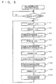
- Fig.3 shows the processing for measuring the oxygen concentration and the NOx concentration repeatedly carried out in the ECU 50
- Fig.4 shows internal resistance detection processing executed within the ECU 50 as interrupt handling (processing) every pre-set time T0, such as 1 second, for detecting the internal resistance RVS of the Vs cell 6 for controlling the current conduction to the heaters 12, 14.
- the oxygen concentration and NOx concentration measurement processing first conducts the current through the heaters 12, 14 at step S100 in order to judge whether or not the NOx sensor 2 has become activated by current supply to the heaters 12, 14 for awaiting activation of the NOx sensor 2 by way of activation judgment processing.
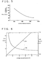
- This activation judgment processing is executed by judging whether or not the internal resistance RVS of the Vs cell 6 as detected by internal resistance detection processing as later explained has become not higher than a pre-set activation judgment value. That is, since the internal resistance of the Vs cell 6 is decreased with rise in the device temperature and with activation of the Vs cell 6, as shown in Fig.5, the step S100 judges whether or not, after starting current supply to the heaters 12, 14, the internal resistance RVS of the Vs cell 6 has become not higher than a pre-set activation judgment value in order to judge whether or not the device temperature has reached a pre-set activation temperature.
- the switch SW1 in a driving circuit 40 is controlled to be turned on, while the switches SW2, SW3 are controlled to be turned off, by the initializing processing, not shown.
- the operation of the differential amplifier AMP in the driving circuit 40 is halted by the activation judgment processing at S100. The reason is that, as long as the NOx censor 2 is not activated, the internal resistance RVS in the Vs cell 6 is large, so that the voltage (potential) Vs of the porous electrode 6c entered to the differential amplifier AMP becomes excessive, such that, if the differential amplifier AMP is actuated, an excess current flows through the first pump cell 4.
- step S110 to read in a detection signal VIP2 entered from the resistor R3 of the detection circit 42, to execute processing as a nitrogen oxide concentration measurement means for detecting the second pump current IP2.
- step S120 the detection signal VIP1 entered via resistor R0 of the driving circuit 40 is read to execute processing as oxygen concentration measurement means for detecting the first pump current IP1.
- a reference correction amount for the second pump current IP2 is calculated based on the detected first pump current IP1.
- the second pump current IP2 varies in accordance with the NOx concentration in the gas being measured, it is also influenced by the oxygen concentration in the gas being measured.
- the first pump current IP1 varies with a constant gradient in keeping with the oxygen concentration in the gas under measurement
- the second pump current IP2 varies also under the influence of the oxygen concentration in the gas under measurement.
- the value of the second pump current IP2 corresponding to the oxygen concentration obtained on measuring the gas under measurement free of NOx as described above is previously stored in a recording medium, such as ROM, as an offset value for correcting the second pump current IP2, the oxygen concentration in the gas under measurement is detected from the first pump current IP1 and the offset value corresponding to this oxygen concentration is read out from the previously stored offset value data for setting as the above-mentioned reference correction amount.
- a map having stored therein an offset value associated with the first pump current IP1 ( reference correction amount) is used, and this map is retrieved using the first pump current IP1 as a parameter, for directly finding a reference correction amount from the first pump current IP1.
- step S140 for reading in the internal resistance RVS of the Vs cell 6 obtained by the internal resistance detection processing as later explained.
- the temperature correction amount for the second pump current IP2 is calculated based on the read value of the internal resistance RVS.
- the current supplied to the heaters 12, 14 is controlled so that the detected value of the internal resistance RVS of the Vs cell 6 will assume a pre-set value, in other words, so that the temperature of the NOx sensor 2 will assume a pre-set target temperature.
- the temperature control cannot follow up the temperature changes in the gas under measurement, such that the temperature of the NOx sensor 2 may be occasionally changed based on changes in the temperature of the measured gas.
- Fig.7 shows an example of measured results of temperature changes in the NOx sensor 2 when the NOx sensor 2 is mounted in an exhaust gas pipe of an internal combustion engine and the measurement device of the present embodiment is in operation for measuring the NOx concentration in the exhaust gas of the internal combustion engine.
- the exhaust gas temperature is transiently decresed with an increased amount of air intaken upon acceleration of the internal combustion engine, or if the exhaust gas temperature is transiently raised with a decreased amount of air taken upon deceleration thereof, both the first pump current IP1 and the second pump current IP2 are changed under the influence of such temperature changes despite temperature control as later explained.
- the temperature of the Vs cell 6 is obtained from the internal resistance RVS of the Vs cell 6 and, using a map for calculating the amount of temperature correction shown for example in Fig.8, for enabling correct measurement of the NOx concentration from the second pump current IP2 even if the temperature of the measured gas is changed acutely.
- the map shown in Fig.8 is designed for finding the amount of temperature correction from the device temperature of the Vs cell 6.
- a map is prepared beforehand for calculating the amount of temperature correction having the internal resistance RVS of the Vs cell 6 as a parameter, the amount of temperature correction can be obtained directly from the internal resistance RVS without the necessity of recalculating (or recovering) the internal resistance RVS into temperature. It is also possible to pre-set a map having an offset between the device temperature and the target temperature (850°C in Fig.8) in order to find the amount of temperature correction from the deviation from the target value of the device temperature.
- step S150 proceeds transfers to step S160 where the amount of reference correction and the amount of temperature correction are summed to the second pump current IP2 detected at step S110 for correcting the second pump current IP2.
- step S170 the as-corrected second pump current IP2 is outputted to an external device, such as an engine controlling device, as the results of measurement of the NOx concentration.
- the amount of temperature correction for the first pump current IP1 is calculated based on the internal resistance RVS read at step S140.
- the first pump current IP1 detected at S120 is corrected, using the calculated amount of temperature correction and, at the next step S200, the corrected value of the first pump current IP1 is outputted to an electronic equipments, as a result of measurement of the oxygen concentration, before proceeding again to S110.
- the processing at S180 and S190 is the processing for associating the first pump current IP1 with the oxygen concentration in the exhaust gas so that the first pump current IP1 will be associated with the oxygen concentration in the gas under measurement without being influenced by temperature changes in the NOx sensor 2.
- the amount of temperature correction for the first pump current IP1 is found using the pre-set map, as in S150 above.
- the processing of S150, S160, S180 and S190, carried out for correcting the second pump current IP2 associated with the NOx concentration and for correcting the first pump current IP1 associated with the oxygen concentration in accordance with the temperature of the Vs cell 6, corresponds to the correction means.
- the reference correction amount for correcting the second pump current IP2 in accordance with the oxygen concentration in the gas under measurement based on the first pump current IP1 and the reference correction amount for correcting the second pump current IP2 in accordance with the temperature in the Vs cell 6 are separately found to correct the second pump current IP2.
- the correction amount for correcting the second pump current IP2 may be found in accordance with the oxygen concentration in the gas under measurement and the temperature in the Vs cell 6 by setting maps for calculating the reference correction amount from one Vs cell temperature to another and by switching between the maps used for calculating the reference correction amount depending on every Vs cell temperature.
- a two-dimensional map for calculating the correction amount may be pre-set, using the first pump current IP1 and the temperature of the Vs cell 6 (or the internal resistance RVS) as parameters in order to find the correction amount for the second pump current IP2 using this map.
- this processing for detecting the internal resistance has not only the function of temperature detection means for detecting the internal resistance RVS of the Vs cell 6, but also the function of the heater current supply control means for controlling the amount of current supplied to the heaters 12, 14 through the heater current supplying circuit 44 based on the results of detection.
- the voltage Vs on the porous electrode 6c of the Vs cell 6 is read at S210 and set as a basic detection voltage VS1 of the Vs cell 6.
- the switch SW1 which has been on for measuring the concentration, is turned off, while the switch SW2 connected to the constant current source 40b is turned on for causing the constant current to flow in a reverse direction to the flowing direction of the small current in the VP cell 6, that is in a direction of pumping oxygen from the closed space operating so far as an internal oxygen source towards the first measurement chamber 20.
- step S230 it is judged, whether or not a pre-set time T1, such as 60 ⁇ sec, has elapsed after starting the detection processing, to wait until lapse of the pre-set time T1. If the pre-set time T2 has elapsed, the voltage on the porous electrode 6c of the Vs cell 6 is read at step S240 to set the voltage Vs thus read as a resistance detection voltage VS2 of the Vs cell 6.
- a pre-set time T1 such as 60 ⁇ sec
- the processing proceeds to step S250 for judging whether or not the pre-set time T2, such as 100 ⁇ sec, has elapsed since start of the detection processing, to wait until lapse of the pre-set time T2. If the pre-set time T2 has elapsed, the detection processing is started at S260.
- the switch SW2 which has been on for the pre-set time T2, is turned off, while the switch SW3, connected to the constant current source 40c, is turned on, for causing the constant current to flow into the Vs cell 6 in the same direction as the flowing direction of the small current iCP, that is in a direction of pumping oxygen in the first measurement chamber 20 towards the closed space.
- step S270 judges whether or not the pre-set time T3, such as 200 ⁇ sec, has elapsed after start of the detection processing, to wait until lapse of the pre-set time T3. If the pre-set time T3 has elapsed, the switch SW3 is turned off at S280. This turns all of the switches SW1 to SW3 in the driving circuit 40 off.
- the pre-set time T3 such as 200 ⁇ sec
- step S300 the internal resistance RVS of the Vs cell 6 is calculated from this offset ⁇ Vs followd by proceeding to S310. The method for calculating the internal resistance RVS in the present embodiment will be explained subsequently.
- a step S310 processing as heater current supply control means is carried out, in which a control signal (heater control signal) for increasing or decreasing the current to the heaters 12, 14 based on an offset between a calculated internal resistance RVS of the Vs cell 6 and a target value or an offset between a temperature of the Vs cell 6 obtained from the internal resistance RVS and a target temperature is outputted to the heater current supply circuit 44 for controlling the value of the current supplied from the heater current supply circuit 44 to the heaters 12, 14.
- a control signal for increasing or decreasing the current to the heaters 12, 14 based on an offset between a calculated internal resistance RVS of the Vs cell 6 and a target value or an offset between a temperature of the Vs cell 6 obtained from the internal resistance RVS and a target temperature
- the heater current supply circuit 44 is constituted by a switching circuit capable of high-speed switching between the current supply and no current supply, it suffices to control a duty ratio of a driving pulse signal responsible for switching between the current supply and no current supply, whereas, if the heater current supply circuit 44 is constituted by a voltage control circuit capable of controlling an output voltage to the heaters 12, 14, it suffices if the voltage is increased or decreased based on the heater control signal from the ECU 50.
- step S320 for judging whether or not a pre-set time T4, such as 500 ⁇ sec, has elapsed after start of the detection processing, to wait until lapse of the pre-set time T4. If the pre-set time T4 has elapsed, the detection processing is started at S330.
- the switch SW1 which has been off for the pre-set time T4, is turned on to terminate the detection processing for re-starting the operation of measuring the oxygen concentration and the NOx concentration.
- the switch SW1 in the driving circuit 40 is turned off when the processing is started at time point t1 for stopping the supply of the small current iCP to the Vs cell 6 and the pump current control, whereupon the switch SW2 is turned on to cause the constant current to flow through the Vs cell 6 in a direction opposite to the flowing direction of the small current iCP.
- the voltage Vs on the side of the porous electrode 6 at this time is set as a resistor detection voltage VS2 and the internal resistance RVS of the Vs cell 6 is detected from the offset ⁇ Vs between the resistance detection voltage VS2 and the voltage Vs on the side of the porous electrode 6c at the time of starting the detection processing (i.e., basic detection voltage VS1), for the reason which will be now explained.
- the voltage Vs on the porous electrode 6c of the Vs cell 6 is varied not only by the internal resistance RVS of the Vs cell 6 but also by an electro-motive force generated responsive to a ratio between oxygen concentration values at both the electrodes 6b and 6c.
- a current larger than the small current iCP is caused to flow for increasing a voltage drop caused by the internal resistance RVS of the Vs cell 6.
- the oxygen concentration values on the electrodes 6b, 6c of the Vs cell 6 are substantially constant by pump current control and by supply of the small current iCP, respectively, the electromotive force of the Vs cell 6 also becomes substantially constant.
- the constant current is caused to flow across the Vs cell 6 thereupon detecting the voltage Vs on the porous electrode 6c, that is VS2, the internal resistance RVS of the Vs cell 6 can be determined substantially correctly from this voltage value.
- the oxygen concentration in the first measurement chamber 20 is controlled by feedback control of the pump current and hence is fluctuated due to, for example, response delay of the control system, such that it cannot be fixed at a constant concentration value.
- the oxygen concentration in the first measurement chamber 20 is also varied depending on the temperature of the NOx sensor 2.
- the amount of change in the voltage Vs on the porous electrode 6c (offset ⁇ Vs) until a pre-set time, such as 60 ⁇ sec, elapses after the time the constant current for detecting the internal resistance RVS is caused to flow through the Vs cell 6 is detected, and the internal resistance RVS is determined from this offset ⁇ Vs. Based on this, the internal resistance RVS of the Vs cell 6 and hence the device temperature can be accurately determined even if the oxygen concentration in the first measurement chamber 20 is deviated from the target concentration.
- the following may be employed.
- a map having previously stored therein the internal resistance RVS versus the offset ⁇ Vs is provided, and the internal resistance RVS is calculated using this map.
- a resistance detection voltage VS2 is set at a time point t2 upon lapse of a pre-set time interval T1 (at time point t2) after start, the switches SW2 and SW3 are turned off and on, respectively, when another pre-set time, such as 40 ⁇ sec, has elapsed further at time point t3 at which the elapsed time after the start of the detection processing has reached T2.
- another pre-set time such as 40 ⁇ sec
- the switch SW3 is turned off.
- a length of time T4 which elapses after the starting of the processing until operation start of the concentration measurement can be as short as 500 ⁇ sec thus enabling the internal resistance RVS of the Vs cell 6 to be measured with high accuracy without affecting measurement of the oxygen concentration and NOx concentration.
- the temperature of the NOx sensor 2 is detected from the internal resistance RVS of the Vs cell 6 adapted to detect the oxygen concentration in the first measurement chamber 20, and the current supply value to the heaters 12, 14 is controlled so that this temperature will be equal to the target temperature, such as 850°C. If the detected internal resistance RVS or the device temperature obtained from this internal resistance RVS deviates from the target value, the second pump current IP2 and/or the first pump current IP1 representing the results of measurement of the NOx concentration and the oxygen concentration are respectively corrected by the temperature correction value (amount) which is responsive to the offset value thereby temperature-compensating the results of measurement of the NOx concentration and the oxygen concentration. In this manner, with the measurement device for measuring the oxygen concentration and the NOx concentration of the instant embodiment, the oxygen concentration and the NOx concentration can be detected highly accurately at all times without being affected by the temperature of the NOx sensor 2.
- the NOx sensor 2 is comprised of the first pump cell 4, Vs cell 6 and the second pump cell 8, laminated in this order, and the heaters 12, 14 are laminated on both sides in the laminating directing. Moreover, if the NOx sensor 2 is projected along the laminated direction, the diffusion rate regulating layer 4d overlaps diffusion rate regulating layers 6d, 22d, and heater wires 12b, 14b of the heaters 12, 14 are arranged to interpose these diffusion rate regulating layers substantially at the mid positions.
- the cells 4 to 8 can be heated efficiently, using the heaters 12, 14, by the above-described structure of the NOx sensor 2, while the gas under measurement, flowing via these diffusion rate regulating layers into the first measurement chamber 20 and the second measurement chamber 26, can also be heated efficiently. Therefore, in the instant embodiment, the temperature of each cell making up the NOx sensor 2 can be controlled more reliably to the target temperature to improve measurement accuracy of the oxygen concentration and the NOx concentration.
Landscapes
- Chemical & Material Sciences (AREA)
- Life Sciences & Earth Sciences (AREA)
- Health & Medical Sciences (AREA)
- Biochemistry (AREA)
- Chemical Kinetics & Catalysis (AREA)
- Electrochemistry (AREA)
- Physics & Mathematics (AREA)
- Analytical Chemistry (AREA)
- Molecular Biology (AREA)
- General Health & Medical Sciences (AREA)
- General Physics & Mathematics (AREA)
- Immunology (AREA)
- Pathology (AREA)
- Measuring Oxygen Concentration In Cells (AREA)
- Combined Controls Of Internal Combustion Engines (AREA)
- Investigating Or Analyzing Non-Biological Materials By The Use Of Chemical Means (AREA)
Claims (13)
- Utilisation d'un capteur de NOx (2) comportant :pour mesurer une concentration en oxyde d'azote dans un gaz de mesure, comprenant les étapes consistant à :une première chambre de mesure (20) comportant une première cellule de pompage d'oxygène (4) et une cellule de mesure de concentration en oxygène (6), dans laquelle une première couche de régulation de débit de diffusion (4d) fait communiquer ladite première chambre de mesure (20) avec ledit gaz de mesure, et dans laquelle ladite première cellule de pompage d'oxygène (4) comporte une couche d'électrolyte pleine conductrice d'ions oxygène (4a) prise en sandwich entre des électrodes poreuses (4b, 4c) ;une deuxième chambre de mesure (26) comportant une deuxième cellule de pompage d'oxygène (8), dans laquelle ladite deuxième cellule de pompage d'oxygène (8) comporte une couche d'électrolyte pleine conductrice d'ions oxygène (8a) prise en sandwich entre des électrodes poreuses (8b, 8c), et dans laquelle une deuxième couche de régulation de débit de diffusion (6d, 22d) fait communiquer ladite deuxième chambre de mesure (26) avec ladite première chambre de mesure (20) ; etun élément chauffant (12, 14) étant adapté pour chauffer lesdites cellules à une température cible préétablie,mesurer de plus une concentration en oxygène dans le gaz de mesure en fonction d'une valeur dudit premier courant (IP1) circulant dans ladite première cellule de pompage d'oxygène (4),provoquer la circulation d'un petit courant (iCP) dans ladite cellule de mesure de concentration en oxygène (6), et la circulation d'un premier courant (IP1) dans ladite première cellule de pompage d'oxygène (4), de telle sorte qu'une tension de sortie de ladite cellule de mesure de concentration en oxygène (6) est à une valeur préétablie pour réguler une concentration en oxygène dans ladite première chambre de mesure (20) à une valeur constante ;appliquer une tension constante dans ladite deuxième cellule de pompage d'oxygène (8) dans une direction de pompage de l'oxygène hors de ladite deuxième chambre de mesure (26), de façon à décomposer par conséquent l'oxyde d'azote contenu dans ladite deuxième chambre de mesure (26), etmesurer ladite concentration en oxyde d'azote dans le gaz de mesure en fonction d'une valeur d'un deuxième courant (IP2) circulant dans ladite deuxième cellule de pompage d'oxygène (8), et
dans laquelle des moyens de détection de température font circuler un courant pour détecter la résistance interne (RVS) dans ladite cellule de mesure de concentration en oxygène (6) dans une direction, puis dans une direction opposée à la direction précédente du courant de détection de résistance interne. - Utilisation selon la revendication 1, comprenant de plus l'étape consistant à réguler un courant délivré audit élément chauffant de telle sorte que ladite température détectée de ladite cellule de mesure de concentration en oxygène (6) soit ladite température cible préétablie.
- Utilisation selon la revendication 1 ou 2, comprenant de plus l'étape de correction des résultats mesurés de ladite concentration en oxygène et de ladite concentration en oxyde d'azote en fonction d'un écart de ladite température détectée par rapport à ladite température cible de ladite cellule de mesure de concentration en oxygène (6) pour compenser lesdits résultats mesurés pour la température.
- Utilisation selon la revendication 2, le dispositif comprenant de plus des moyens de commande d'alimentation en courant d'élément chauffant (14) commandant le courant délivré audit élément chauffant (12, 14).
- Utilisation selon la revendication 3, le dispositif comprenant de plus un moyen de correction compensant en température les résultats de la mesure de ladite concentration en oxygène et de ladite concentration en oxyde d'azote.
- Utilisation selon l'une des revendications 1 à 5, dans laquelle ledit moyen de détection de température détecte ladite température de ladite cellule de mesure de concentration en oxygène (6) en détectant ladite résistance interne (RVS) de ladite cellule de mesure (6).
- Utilisation selon l'une des revendications 1 à 6, dans laquelle :dans ledit capteur de NOx (2), une électrode (6c) parmi lesdites électrodes (6b, 6c) de ladite cellule de mesure de concentration en oxygène (6) est fermée, ladite électrode fermée étant agencée sur un côté opposé à ladite première chambre de mesure (20) ;une résistance de fuite (6f) est disposée de telle sorte qu'une partie de l'oxygène dans l'espace fermé résultant puisse fuir ; etledit moyen de commande de courant de pompe (40a) pompe l'oxygène hors de ladite première chambre de mesure (20) vers l'intérieur dudit espace fermé de façon à réguler une quantité de courant circulant dans ladite première cellule de pompage d'oxygène (4), de telle sorte que, lorsque ledit espace fermé est amené à fonctionner en source de référence d'oxygène interne, une force électromotrice générée dans ladite cellule de mesure de concentration en oxygène (6) a une valeur constante.
- Utilisation selon l'une des revendications 1 à 7, dans laquelle, dans ledit capteur de NOx (2) :ladite première cellule de pompage d'oxygène (4), ladite cellule de mesure de concentration en oxygène (6) et ladite deuxième cellule de pompage d'oxygène (8) sont constituées par des couches d'électrolyte pleines sous la forme de plaques minces différentes, respectivement ;ladite première chambre de mesure (20) et ladite deuxième chambre de mesure (26) sont constituées par stratification desdites couches d'électrolyte pleines respectives chacune avec un petit espace entre elles, les couches d'électrolyte pleines constituant lesdites première et deuxième cellules de pompage d'oxygène (4, 8) étant dirigées vers l'extérieur ;ledit élément chauffant (12, 14) comprend de préférence, deux substrats d'élément chauffant (12a, 14a) sous la forme de plaques minces qui sont constitués par des substrats d'élément chauffant, avec un câblage d'élément chauffant (12b, 14b) incorporé à l'intérieur de ceux-ci, lesdits substrats d'élément chauffant (12a, 14a) étant de préférence agences sur les deux côtés, dans une direction de stratification, desdites couches d'électrolyte pleines dans ledit capteur de NOx avec un intervalle préétabli entre ceux-ci pour chauffer ledit capteur de NOx ; et/ou dans laquelle :ladite première couche de régulation de débit de diffusion (4d) est disposée dans l'une desdites couches d'électrolyte pleines constituant ladite première cellule de pompage d'oxygène (4), de telle sorte que ladite première couche de régulation du débit de diffusion (4d) est disposée dans une position opposée à une position médiane dudit câblage d'élément chauffant (12b) dans ledit substrat d'élément chauffant (12a).
- Utilisation selon la revendication 8, dans laquelle ladite deuxième couche de régulation de débit de diffusion (6d, 22d) chevauche au moins une partie de ladite première couche de régulation de débit de diffusion (4d) selon une vue dans laquelle ledit capteur de NOx est projeté à partir de ladite direction de stratification desdites couche d'électrolyte pleines, et dans laquelle ladite cellule de mesure de concentration en oxygène (6) est disposée au voisinage de ladite deuxième couche de régulation de débit de diffusion (6d, 22d).
- Utilisation selon l'une quelconque des revendications 1 à 9, dans laquelle une électrode poreuse (6b) parmi lesdites électrodes (6b, 6c) de ladite cellule de mesure de concentration en oxygène (6) est disposée dans ladite première chambre de mesure (20) entourant ladite deuxième couche de régulation de débit de diffusion (6d, 22d).
- Utilisation selon l'une quelconque des revendications 1 à 9, dans laquelle une électrode poreuse (4c) parmi lesdites électrodes (4b, 4c) de ladite première cellule de pompage d'oxygène (4) est disposée dans ladite première chambre de mesure (20) entourant ladite première couche de régulation de débit de diffusion (4d).
- Utilisation selon l'une quelconque des revendications 1 à 11, dans laquelle lesdits moyens de mesure de concentration en oxygène comprennent une unité de calcul électronique (50) comportant un ordinateur calculant ladite concentration en oxygène dudit gaz de mesure en fonction de ladite valeur de courant (IP1) circulant dans ladite première cellule de pompage d'oxygène (4).
- Utilisation selon l'une quelconque des revendications 1 à 12, dans laquelle ledit moyen de correction de température comprend un calculateur calculant une quantité de correction de température de ladite concentration en oxygène et de ladite concentration en oxyde d'azote, respectivement, sur la base d'une carte de correction en fonction d'un écart par rapport à ladite température cible préétablie dudit dispositif.
Priority Applications (1)
| Application Number | Priority Date | Filing Date | Title |
|---|---|---|---|
| EP03007539A EP1324028B1 (fr) | 1996-11-08 | 1997-11-10 | Méthode et appareil pour mesurer la concentration d'oxygène et d'oxyde d'azote |
Applications Claiming Priority (3)
| Application Number | Priority Date | Filing Date | Title |
|---|---|---|---|
| JP296676/96 | 1996-11-08 | ||
| JP29667696 | 1996-11-08 | ||
| JP29667696A JP3332761B2 (ja) | 1996-11-08 | 1996-11-08 | 酸素濃度・窒素酸化物濃度測定方法及び装置 |
Related Child Applications (1)
| Application Number | Title | Priority Date | Filing Date |
|---|---|---|---|
| EP03007539A Division EP1324028B1 (fr) | 1996-11-08 | 1997-11-10 | Méthode et appareil pour mesurer la concentration d'oxygène et d'oxyde d'azote |
Publications (3)
| Publication Number | Publication Date |
|---|---|
| EP0841562A2 EP0841562A2 (fr) | 1998-05-13 |
| EP0841562A3 EP0841562A3 (fr) | 1998-10-07 |
| EP0841562B1 true EP0841562B1 (fr) | 2005-08-17 |
Family
ID=17836640
Family Applications (2)
| Application Number | Title | Priority Date | Filing Date |
|---|---|---|---|
| EP97119646A Expired - Lifetime EP0841562B1 (fr) | 1996-11-08 | 1997-11-10 | Utilisation d'un capteur pour mesurer la concentration d'oxyde d'azote |
| EP03007539A Expired - Lifetime EP1324028B1 (fr) | 1996-11-08 | 1997-11-10 | Méthode et appareil pour mesurer la concentration d'oxygène et d'oxyde d'azote |
Family Applications After (1)
| Application Number | Title | Priority Date | Filing Date |
|---|---|---|---|
| EP03007539A Expired - Lifetime EP1324028B1 (fr) | 1996-11-08 | 1997-11-10 | Méthode et appareil pour mesurer la concentration d'oxygène et d'oxyde d'azote |
Country Status (4)
| Country | Link |
|---|---|
| US (1) | US6214207B1 (fr) |
| EP (2) | EP0841562B1 (fr) |
| JP (1) | JP3332761B2 (fr) |
| DE (2) | DE69732582T2 (fr) |
Cited By (1)
| Publication number | Priority date | Publication date | Assignee | Title |
|---|---|---|---|---|
| US6990799B2 (en) | 2000-03-17 | 2006-01-31 | Ford Global Technologies, Llc | Method of determining emission control system operability |
Families Citing this family (79)
| Publication number | Priority date | Publication date | Assignee | Title |
|---|---|---|---|---|
| US6228252B1 (en) | 1997-02-13 | 2001-05-08 | Ngk Spark Plug Co. Ltd. | Apparatus for detecting concentration of nitrogen oxide |
| EP0878709B1 (fr) * | 1997-03-21 | 2004-08-25 | NGK Spark Plug Co. Ltd. | Procédé et appareil de mesure de la concentration d'oxydes d'azote |
| EP0937979A3 (fr) * | 1998-02-20 | 2000-11-22 | NGK Spark Plug Co. Ltd. | Circuit de contrôle pour un capteur de NOx et système de capteur de NOx utilisant ce circuit |
| EP0981046A1 (fr) * | 1998-08-10 | 2000-02-23 | Ngk Spark Plug Co., Ltd | Procédé de mesure de la concentration d'un composant d'un gaz |
| JP3440034B2 (ja) * | 1998-08-10 | 2003-08-25 | 日本特殊陶業株式会社 | 被測定ガス中の窒素酸化物濃度の測定方法 |
| JP4005273B2 (ja) | 1998-09-16 | 2007-11-07 | 株式会社デンソー | ガス濃度検出装置 |
| JP2000137018A (ja) | 1998-11-02 | 2000-05-16 | Denso Corp | ガス濃度検出装置とそれに用いるガス濃度センサ |
| JP3560316B2 (ja) * | 1998-11-25 | 2004-09-02 | 日本特殊陶業株式会社 | ガスセンサとその製造方法及びガスセンサシステム |
| JP4153113B2 (ja) * | 1998-12-04 | 2008-09-17 | 株式会社デンソー | ガス濃度検出装置 |
| IT1308992B1 (it) * | 1999-02-09 | 2002-01-15 | Magneti Marelli Spa | Metodo di controllo e di diagnosi del riscaldatore di un sensoresensibile alla composizione dei gas di scarico di un motore. |
| DE19907947B4 (de) * | 1999-02-24 | 2004-01-29 | Siemens Ag | Schaltung für einen NOx-Meßaufnehmer |
| DE19907946C2 (de) * | 1999-02-24 | 2003-12-11 | Siemens Ag | Schaltung für einen NOx-Meßaufnehmer |
| DE19912102C2 (de) * | 1999-03-18 | 2002-09-05 | Bosch Gmbh Robert | Elektrochemischer Gassensor |
| WO2000071870A1 (fr) * | 1999-05-19 | 2000-11-30 | Robert Bosch Gmbh | Procede pour obtenir, de maniere definie, un melange de gaz de combustion soit riche soit pauvre |
| US6723217B1 (en) * | 1999-10-20 | 2004-04-20 | Delphi Technologies, Inc. | Method and device for pumping oxygen into a gas sensor |
| KR20020060713A (ko) * | 1999-10-20 | 2002-07-18 | 덴턴 마이클 | 가스센서로 산소를 펌핑하는 방법 및 장치 |
| US6360530B1 (en) | 2000-03-17 | 2002-03-26 | Ford Global Technologies, Inc. | Method and apparatus for measuring lean-burn engine emissions |
| US6843051B1 (en) * | 2000-03-17 | 2005-01-18 | Ford Global Technologies, Llc | Method and apparatus for controlling lean-burn engine to purge trap of stored NOx |
| US6860100B1 (en) * | 2000-03-17 | 2005-03-01 | Ford Global Technologies, Llc | Degradation detection method for an engine having a NOx sensor |
| US6490855B1 (en) * | 2000-04-06 | 2002-12-10 | Ford Global Technologies, Inc. | Fueling control during emission control device purging |
| US6389803B1 (en) * | 2000-08-02 | 2002-05-21 | Ford Global Technologies, Inc. | Emission control for improved vehicle performance |
| JP4682465B2 (ja) * | 2000-10-31 | 2011-05-11 | 株式会社デンソー | ガス濃度検出装置 |
| CA2431018A1 (fr) * | 2000-12-07 | 2003-01-30 | Aep Emtech, Llc | Detecteur d'oxygene et de nox combine |
| JP2002372514A (ja) * | 2001-06-15 | 2002-12-26 | Denso Corp | ガス濃度検出装置 |
| US6502387B1 (en) | 2001-06-19 | 2003-01-07 | Ford Global Technologies, Inc. | Method and system for controlling storage and release of exhaust gas constituents in an emission control device |
| US6615577B2 (en) | 2001-06-19 | 2003-09-09 | Ford Global Technologies, Llc | Method and system for controlling a regeneration cycle of an emission control device |
| US6553754B2 (en) | 2001-06-19 | 2003-04-29 | Ford Global Technologies, Inc. | Method and system for controlling an emission control device based on depletion of device storage capacity |
| US6691020B2 (en) | 2001-06-19 | 2004-02-10 | Ford Global Technologies, Llc | Method and system for optimizing purge of exhaust gas constituent stored in an emission control device |
| US6539706B2 (en) | 2001-06-19 | 2003-04-01 | Ford Global Technologies, Inc. | Method and system for preconditioning an emission control device for operation about stoichiometry |
| US6487853B1 (en) | 2001-06-19 | 2002-12-03 | Ford Global Technologies. Inc. | Method and system for reducing lean-burn vehicle emissions using a downstream reductant sensor |
| US6467259B1 (en) | 2001-06-19 | 2002-10-22 | Ford Global Technologies, Inc. | Method and system for operating dual-exhaust engine |
| US6453666B1 (en) | 2001-06-19 | 2002-09-24 | Ford Global Technologies, Inc. | Method and system for reducing vehicle tailpipe emissions when operating lean |
| US6694244B2 (en) | 2001-06-19 | 2004-02-17 | Ford Global Technologies, Llc | Method for quantifying oxygen stored in a vehicle emission control device |
| US6490860B1 (en) | 2001-06-19 | 2002-12-10 | Ford Global Technologies, Inc. | Open-loop method and system for controlling the storage and release cycles of an emission control device |
| US6650991B2 (en) | 2001-06-19 | 2003-11-18 | Ford Global Technologies, Llc | Closed-loop method and system for purging a vehicle emission control |
| US6546718B2 (en) | 2001-06-19 | 2003-04-15 | Ford Global Technologies, Inc. | Method and system for reducing vehicle emissions using a sensor downstream of an emission control device |
| US6463733B1 (en) | 2001-06-19 | 2002-10-15 | Ford Global Technologies, Inc. | Method and system for optimizing open-loop fill and purge times for an emission control device |
| US6604504B2 (en) | 2001-06-19 | 2003-08-12 | Ford Global Technologies, Llc | Method and system for transitioning between lean and stoichiometric operation of a lean-burn engine |
| JP3776386B2 (ja) * | 2001-09-05 | 2006-05-17 | 株式会社デンソー | ガスセンサ素子及びガス濃度の検出方法 |
| DE10202859A1 (de) * | 2002-01-24 | 2003-08-21 | Volkswagen Ag | Verfahren zur Bestimmung der NOx-Konzentration |
| JPWO2003083465A1 (ja) * | 2002-03-29 | 2005-08-04 | 日本特殊陶業株式会社 | Nox測定装置、noxセンサの自己診断装置及びその自己診断方法 |
| GB0224267D0 (en) * | 2002-10-18 | 2002-11-27 | Univ Middlesex Serv Ltd | Sensors |
| DE10257284A1 (de) * | 2002-12-07 | 2004-06-24 | Robert Bosch Gmbh | Schaltungsanordnung zum Betreiben eines Gassensors |
| DE10311816B4 (de) * | 2003-03-18 | 2005-12-29 | Siemens Ag | Vorrichtung und Verfahren zur Messung der NOx-Konzentration in einem Messgas |
| JP4033072B2 (ja) * | 2003-04-23 | 2008-01-16 | トヨタ自動車株式会社 | ガス濃度センサの制御装置 |
| US20050161325A1 (en) | 2004-01-27 | 2005-07-28 | Ngk Spark Plug Co., Ltd. | Gas detecting system |
| JP4048200B2 (ja) * | 2004-01-27 | 2008-02-13 | 日本特殊陶業株式会社 | ガス検出システム |
| DE102004018871B4 (de) * | 2004-04-19 | 2006-03-09 | Siemens Ag | Verfahren und Vorrichtung zum Betreiben einer Abgas-Analyse-Sensorzelle |
| US20080017510A1 (en) * | 2004-05-26 | 2008-01-24 | Nair Balakrishnan G | NOx Gas Sensor Method and Device |
| US7114325B2 (en) * | 2004-07-23 | 2006-10-03 | Ford Global Technologies, Llc | Control system with a sensor |
| US7611612B2 (en) * | 2005-07-14 | 2009-11-03 | Ceramatec, Inc. | Multilayer ceramic NOx gas sensor device |
| WO2008103311A2 (fr) * | 2007-02-16 | 2008-08-28 | Ceramatec, Inc. | Capteur de nox à sélectivité et sensibilité améliorées |
| EP2083263A3 (fr) | 2008-01-24 | 2015-09-02 | NGK Spark Plug Co., Ltd. | Capteur de NOx et son procédé de fabrication |
| JP4940172B2 (ja) | 2008-03-05 | 2012-05-30 | 日本特殊陶業株式会社 | NOxセンサ制御装置及び車両側制御装置 |
| JP5350670B2 (ja) * | 2008-04-28 | 2013-11-27 | 日本特殊陶業株式会社 | 燃料電池用水蒸気センサの制御装置、燃料電池用水蒸気センサ、及び燃料電池システム |
| US8121744B2 (en) * | 2008-06-20 | 2012-02-21 | GM Global Technology Operations LLC | Control system and method for oxygen sensor heater control |
| ES2616513T3 (es) * | 2008-09-03 | 2017-06-13 | Testo Ag | Procedimiento y dispositivo para la captación de valores de medición e indicación de los valores de medición |
| JP4995800B2 (ja) | 2008-10-29 | 2012-08-08 | 日本特殊陶業株式会社 | 窒素酸化物浄化触媒の異常検出方法および装置 |
| US8418439B2 (en) * | 2009-02-18 | 2013-04-16 | Ford Global Technologies, Llc | NOx sensor ambient temperature compensation |
| DE102009026418B4 (de) * | 2009-05-22 | 2023-07-13 | Robert Bosch Gmbh | Konditionierung eines Sensorelements in einem Brennerprüferstand bei mindestens 1000°C und Konditionierungsstrom |
| JP5119305B2 (ja) | 2010-01-14 | 2013-01-16 | 日本特殊陶業株式会社 | ガスセンサ制御装置及びガスセンサ制御方法 |
| JP5465263B2 (ja) | 2011-02-04 | 2014-04-09 | 日本特殊陶業株式会社 | NOxセンサ制御装置 |
| US9164080B2 (en) | 2012-06-11 | 2015-10-20 | Ohio State Innovation Foundation | System and method for sensing NO |
| CN102890109B (zh) * | 2012-10-16 | 2014-08-06 | 常州联德电子有限公司 | 一种氮氧传感器及其制作方法 |
| DE102012220567B4 (de) * | 2012-11-12 | 2025-12-11 | Robert Bosch Gmbh | Verfahren zum Betrieb eines Sensorelements |
| DE102012224374A1 (de) * | 2012-12-27 | 2014-07-03 | Robert Bosch Gmbh | Verfahren zur Diagnose einer elektrischen Leitung zu einer Elektrode eines Sensorelements zur Erfassung mindestens einer Eigenschaft eines Messgases in einem Messgasraum |
| DE102014214620A1 (de) * | 2014-07-25 | 2016-01-28 | Robert Bosch Gmbh | Vorrichtung zur Gasanalyse mit thermisch aktivierbarem Konversionselement |
| DE102015205971B4 (de) | 2015-04-01 | 2019-12-24 | Continental Automotive Gmbh | Verfahren zum Betreiben einer Sonde |
| DE102016206991A1 (de) | 2016-04-25 | 2017-10-26 | Continental Automotive Gmbh | Verfahren zur Diagnose eines Stickoxidsensors in einer Brennkraftmaschine |
| JP6923345B2 (ja) | 2017-04-14 | 2021-08-18 | 日本特殊陶業株式会社 | センサ装置およびセンサユニット |
| DE102018201266A1 (de) | 2018-01-29 | 2019-08-01 | Continental Automotive Gmbh | Verfahren zum Ermitteln eines angepassten Kompensationsfaktors eines amperometrischen Sensors und amperometrischer Sensor |
| JP6791214B2 (ja) * | 2018-07-13 | 2020-11-25 | 横河電機株式会社 | 分光分析装置 |
| DE102018219567A1 (de) | 2018-11-15 | 2020-05-20 | Continental Automotive Gmbh | Verfahren zum Erkennen einer Anpassungsnotwendigkeit eines Kompensationsfaktors eines amperometrischen Sensors und amperometrischer Sensor |
| DE102019203749A1 (de) * | 2019-03-19 | 2020-04-02 | Vitesco Technologies GmbH | Verfahren zum Ermitteln eines Fehlers eines Abgassensors einer Brennkraftmaschine |
| DE102019203707B3 (de) | 2019-03-19 | 2020-07-02 | Vitesco Technologies GmbH | Verfahren zum Ermitteln eines Fehlers eines Abgassensors einer Brennkraftmaschine |
| DE102019203704B4 (de) | 2019-03-19 | 2023-10-26 | Vitesco Technologies GmbH | Verfahren zum Steuern des Betriebs eines mit zwei Messpfaden ausgestatteten Abgassensors einer Brennkraftmaschine zum Ermitteln eines Fehlers des Abgassensors durch Vergleich der Pumpströme beider Messpfade |
| DE102019209456B3 (de) | 2019-06-28 | 2020-06-18 | Vitesco Technologies GmbH | Verfahren zum signal-optimierten Betreiben eines NOx/NH3-Abgassensors für eine Brennkraftmaschine |
| CN112198206A (zh) * | 2020-09-21 | 2021-01-08 | 苏州禾苏传感器科技有限公司 | 一种电化学气体传感器芯片 |
| CN113250798B (zh) * | 2021-05-14 | 2022-03-25 | 高鑫环保科技(苏州)有限公司 | 一种氮氧传感器 |
Family Cites Families (25)
| Publication number | Priority date | Publication date | Assignee | Title |
|---|---|---|---|---|
| JPS57192856A (en) | 1981-05-25 | 1982-11-27 | Ngk Insulators Ltd | Oxygen concentration detector |
| JPS57200850A (en) * | 1981-06-04 | 1982-12-09 | Ngk Insulators Ltd | Detector for oxygen concentration |
| JPS6039549A (ja) * | 1983-08-12 | 1985-03-01 | Mitsubishi Electric Corp | 機関の空燃比センサ |
| JPH0789109B2 (ja) | 1985-09-30 | 1995-09-27 | 本田技研工業株式会社 | 酸素濃度検出装置 |
| JPH0814570B2 (ja) | 1986-02-07 | 1996-02-14 | 日本特殊陶業株式会社 | 空燃比センサ |
| JPH0672861B2 (ja) | 1986-08-04 | 1994-09-14 | 日本碍子株式会社 | NOxセンサ |
| US4875990A (en) | 1986-08-28 | 1989-10-24 | Ngk Insulators, Ltd. | Oxygen concentration measuring device |
| JPH0676990B2 (ja) * | 1986-09-30 | 1994-09-28 | 日本碍子株式会社 | 高温ガス中の二酸化炭素および水分測定装置 |
| JPH07119739B2 (ja) | 1986-12-27 | 1995-12-20 | 日本碍子株式会社 | 空燃比測定装置における出力補正方法 |
| US4909072A (en) * | 1988-07-22 | 1990-03-20 | Ford Motor Company | Measurement and control of exhaust gas recirculation with an oxygen pumping device |
| US5145566A (en) * | 1988-09-30 | 1992-09-08 | Ford Motor Company | Method for determining relative amount of oxygen containing gas in a gas mixture |
| JPH046460A (ja) * | 1990-04-25 | 1992-01-10 | Nippon Soken Inc | 酸素濃度センサ |
| JP2846735B2 (ja) | 1990-11-30 | 1999-01-13 | 日本碍子株式会社 | 空燃比センサの出力補正方法 |
| JPH04348268A (ja) * | 1991-05-24 | 1992-12-03 | Japan Electron Control Syst Co Ltd | 排気ガスセンサ |
| JP2855971B2 (ja) | 1992-06-25 | 1999-02-10 | 三菱電機株式会社 | 空燃比センサ |
| US5413683A (en) * | 1993-03-25 | 1995-05-09 | Ngk Insulators Ltd. | Oxygen sensing apparatus and method using electrochemical oxygen pumping action to provide reference gas |
| DE4344961B4 (de) | 1993-12-30 | 2004-05-06 | Robert Bosch Gmbh | Auswertevorrichtung für das Signal einer Sauerstoffsonde |
| JP2885336B2 (ja) | 1994-04-21 | 1999-04-19 | 日本碍子株式会社 | 被測定ガス中のNOx濃度の測定方法及び測定装置 |
| GB2288873A (en) * | 1994-04-28 | 1995-11-01 | Univ Middlesex Serv Ltd | Multi-component gas analysis apparatus |
| JP3481344B2 (ja) * | 1995-04-19 | 2003-12-22 | 日本碍子株式会社 | 排ガス浄化用触媒の劣化検知方法及びそのためのシステム |
| JP3436611B2 (ja) * | 1995-04-28 | 2003-08-11 | 日本特殊陶業株式会社 | 酸素センサ用ヒータの通電制御方法及び装置 |
| JP3050781B2 (ja) * | 1995-10-20 | 2000-06-12 | 日本碍子株式会社 | 被測定ガス中の所定ガス成分の測定方法及び測定装置 |
| JP3684686B2 (ja) * | 1995-12-18 | 2005-08-17 | 株式会社デンソー | 酸素濃度判定装置 |
| JPH09318594A (ja) * | 1996-03-25 | 1997-12-12 | Ngk Insulators Ltd | ガスセンサおよび被測定ガス中の特定成分量の測定方法 |
| JP3470012B2 (ja) * | 1996-05-30 | 2003-11-25 | 日本碍子株式会社 | ガス分析計及びその校正方法 |
-
1996
- 1996-11-08 JP JP29667696A patent/JP3332761B2/ja not_active Expired - Fee Related
-
1997
- 1997-11-06 US US08/965,512 patent/US6214207B1/en not_active Expired - Lifetime
- 1997-11-10 DE DE69732582T patent/DE69732582T2/de not_active Expired - Lifetime
- 1997-11-10 EP EP97119646A patent/EP0841562B1/fr not_active Expired - Lifetime
- 1997-11-10 EP EP03007539A patent/EP1324028B1/fr not_active Expired - Lifetime
- 1997-11-10 DE DE69733988T patent/DE69733988T2/de not_active Expired - Lifetime
Cited By (1)
| Publication number | Priority date | Publication date | Assignee | Title |
|---|---|---|---|---|
| US6990799B2 (en) | 2000-03-17 | 2006-01-31 | Ford Global Technologies, Llc | Method of determining emission control system operability |
Also Published As
| Publication number | Publication date |
|---|---|
| JP3332761B2 (ja) | 2002-10-07 |
| EP1324028B1 (fr) | 2005-02-23 |
| DE69732582T2 (de) | 2006-05-11 |
| DE69733988T2 (de) | 2006-06-08 |
| JPH10142194A (ja) | 1998-05-29 |
| EP0841562A3 (fr) | 1998-10-07 |
| DE69733988D1 (de) | 2005-09-22 |
| DE69732582D1 (de) | 2005-03-31 |
| EP0841562A2 (fr) | 1998-05-13 |
| US6214207B1 (en) | 2001-04-10 |
| EP1324028A1 (fr) | 2003-07-02 |
Similar Documents
| Publication | Publication Date | Title |
|---|---|---|
| EP0841562B1 (fr) | Utilisation d'un capteur pour mesurer la concentration d'oxyde d'azote | |
| EP0859232B1 (fr) | Appareil pour la determination de la concentration d'oxides d'azote | |
| US6635161B2 (en) | NOx sensor control circuit unit and NOx sensor system using the same | |
| US6082176A (en) | NOx-concentration detecting apparatus | |
| EP0869356B1 (fr) | Capteur de NOx | |
| EP1074834B1 (fr) | Procédé et appareil de mesure de la concentration d'oxydes d'azote | |
| US4722779A (en) | Air/fuel ratio sensor | |
| US6309536B1 (en) | Method and apparatus for detecting a functional condition on an NOx occlusion catalyst | |
| JP3677162B2 (ja) | ガスセンサ用制御回路ユニット及びそれを用いたガスセンサシステム | |
| JPH1172478A (ja) | 酸化物ガス濃度検出装置及びそれに用いられる記憶媒体 | |
| JP3431822B2 (ja) | 窒素酸化物濃度検出装置 | |
| EP0178149B1 (fr) | Procédé de détection de la pression partielle d'oxygène | |
| JP4572735B2 (ja) | ガス濃度検出装置 | |
| JP3352002B2 (ja) | 窒素酸化物吸蔵触媒の機能低下検出方法及び装置 | |
| JP3431518B2 (ja) | 窒素酸化物吸蔵触媒の機能状態検出方法及び装置 | |
| JPH1164276A (ja) | 酸化物ガス濃度検出装置 | |
| JP4404595B2 (ja) | ガスセンサ用制御回路ユニット | |
| JP3382861B2 (ja) | 窒素酸化物吸蔵触媒の機能状態検出装置 | |
| JPH0643986B2 (ja) | 空燃比センサの活性化検出装置 | |
| JP2001059833A (ja) | 排ガス濃度検出装置 | |
| JPH10325825A (ja) | 窒素酸化物濃度検出器 | |
| JPH0635956B2 (ja) | 内燃機関の空燃比検出装置 | |
| JPS62197759A (ja) | 空燃比センサの活性化検出装置 |
Legal Events
| Date | Code | Title | Description |
|---|---|---|---|
| PUAI | Public reference made under article 153(3) epc to a published international application that has entered the european phase |
Free format text: ORIGINAL CODE: 0009012 |
|
| AK | Designated contracting states |
Kind code of ref document: A2 Designated state(s): DE FR GB IT |
|
| AX | Request for extension of the european patent |
Free format text: AL;LT;LV;MK;RO;SI |
|
| PUAL | Search report despatched |
Free format text: ORIGINAL CODE: 0009013 |
|
| AK | Designated contracting states |
Kind code of ref document: A3 Designated state(s): AT BE CH DE DK ES FI FR GB GR IE IT LI LU MC NL PT SE |
|
| 17P | Request for examination filed |
Effective date: 19981016 |
|
| AKX | Designation fees paid |
Free format text: DE FR GB IT |
|
| 17Q | First examination report despatched |
Effective date: 20021122 |
|
| GRAP | Despatch of communication of intention to grant a patent |
Free format text: ORIGINAL CODE: EPIDOSNIGR1 |
|
| RTI1 | Title (correction) |
Free format text: USE OF AN NOX SENSOR FOR MEASURING NITROGEN OXIDE CONCENTRATION |
|
| GRAS | Grant fee paid |
Free format text: ORIGINAL CODE: EPIDOSNIGR3 |
|
| GRAA | (expected) grant |
Free format text: ORIGINAL CODE: 0009210 |
|
| AK | Designated contracting states |
Kind code of ref document: B1 Designated state(s): DE FR GB IT |
|
| PG25 | Lapsed in a contracting state [announced via postgrant information from national office to epo] |
Ref country code: IT Free format text: LAPSE BECAUSE OF FAILURE TO SUBMIT A TRANSLATION OF THE DESCRIPTION OR TO PAY THE FEE WITHIN THE PRE;WARNING: LAPSES OF ITALIAN PATENTS WITH EFFECTIVE DATE BEFORE 2007 MAY HAVE OCCURRED AT ANY TIME BEFORE 2007. THE CORRECT EFFECTIVE DATE MAY BE DIFFERENT FROM THE ONE RECORDED.SCRIBED TIME-LIMIT Effective date: 20050817 |
|
| REG | Reference to a national code |
Ref country code: GB Ref legal event code: FG4D |
|
| REF | Corresponds to: |
Ref document number: 69733988 Country of ref document: DE Date of ref document: 20050922 Kind code of ref document: P |
|
| PG25 | Lapsed in a contracting state [announced via postgrant information from national office to epo] |
Ref country code: GB Free format text: LAPSE BECAUSE OF NON-PAYMENT OF DUE FEES Effective date: 20051117 |
|
| ET | Fr: translation filed | ||
| PLBE | No opposition filed within time limit |
Free format text: ORIGINAL CODE: 0009261 |
|
| STAA | Information on the status of an ep patent application or granted ep patent |
Free format text: STATUS: NO OPPOSITION FILED WITHIN TIME LIMIT |
|
| 26N | No opposition filed |
Effective date: 20060518 |
|
| GBPC | Gb: european patent ceased through non-payment of renewal fee |
Effective date: 20051117 |
|
| REG | Reference to a national code |
Ref country code: FR Ref legal event code: PLFP Year of fee payment: 19 |
|
| REG | Reference to a national code |
Ref country code: FR Ref legal event code: PLFP Year of fee payment: 20 |
|
| PGFP | Annual fee paid to national office [announced via postgrant information from national office to epo] |
Ref country code: DE Payment date: 20161101 Year of fee payment: 20 Ref country code: FR Payment date: 20161014 Year of fee payment: 20 |
|
| REG | Reference to a national code |
Ref country code: DE Ref legal event code: R071 Ref document number: 69733988 Country of ref document: DE |