EP0842306B2 - Verbesserungen in und betreffend Verfahren zur Verbesserung der Sputterabscheidung von Metall-Schwefel-Beschichtungen, z.B. Molybdändisulfid Beschichtungen und verbesserten Beschichtungen - Google Patents
Verbesserungen in und betreffend Verfahren zur Verbesserung der Sputterabscheidung von Metall-Schwefel-Beschichtungen, z.B. Molybdändisulfid Beschichtungen und verbesserten Beschichtungen Download PDFInfo
- Publication number
- EP0842306B2 EP0842306B2 EP96924987A EP96924987A EP0842306B2 EP 0842306 B2 EP0842306 B2 EP 0842306B2 EP 96924987 A EP96924987 A EP 96924987A EP 96924987 A EP96924987 A EP 96924987A EP 0842306 B2 EP0842306 B2 EP 0842306B2
- Authority
- EP
- European Patent Office
- Prior art keywords
- metal
- coating
- target
- coatings
- mos
- Prior art date
- Legal status (The legal status is an assumption and is not a legal conclusion. Google has not performed a legal analysis and makes no representation as to the accuracy of the status listed.)
- Expired - Lifetime
Links
Images


Classifications
-
- C—CHEMISTRY; METALLURGY
- C23—COATING METALLIC MATERIAL; COATING MATERIAL WITH METALLIC MATERIAL; CHEMICAL SURFACE TREATMENT; DIFFUSION TREATMENT OF METALLIC MATERIAL; COATING BY VACUUM EVAPORATION, BY SPUTTERING, BY ION IMPLANTATION OR BY CHEMICAL VAPOUR DEPOSITION, IN GENERAL; INHIBITING CORROSION OF METALLIC MATERIAL OR INCRUSTATION IN GENERAL
- C23C—COATING METALLIC MATERIAL; COATING MATERIAL WITH METALLIC MATERIAL; SURFACE TREATMENT OF METALLIC MATERIAL BY DIFFUSION INTO THE SURFACE, BY CHEMICAL CONVERSION OR SUBSTITUTION; COATING BY VACUUM EVAPORATION, BY SPUTTERING, BY ION IMPLANTATION OR BY CHEMICAL VAPOUR DEPOSITION, IN GENERAL
- C23C14/00—Coating by vacuum evaporation, by sputtering or by ion implantation of the coating forming material
- C23C14/22—Coating by vacuum evaporation, by sputtering or by ion implantation of the coating forming material characterised by the process of coating
- C23C14/56—Apparatus specially adapted for continuous coating; Arrangements for maintaining the vacuum, e.g. vacuum locks
- C23C14/564—Means for minimising impurities in the coating chamber such as dust, moisture, residual gases
-
- C—CHEMISTRY; METALLURGY
- C23—COATING METALLIC MATERIAL; COATING MATERIAL WITH METALLIC MATERIAL; CHEMICAL SURFACE TREATMENT; DIFFUSION TREATMENT OF METALLIC MATERIAL; COATING BY VACUUM EVAPORATION, BY SPUTTERING, BY ION IMPLANTATION OR BY CHEMICAL VAPOUR DEPOSITION, IN GENERAL; INHIBITING CORROSION OF METALLIC MATERIAL OR INCRUSTATION IN GENERAL
- C23C—COATING METALLIC MATERIAL; COATING MATERIAL WITH METALLIC MATERIAL; SURFACE TREATMENT OF METALLIC MATERIAL BY DIFFUSION INTO THE SURFACE, BY CHEMICAL CONVERSION OR SUBSTITUTION; COATING BY VACUUM EVAPORATION, BY SPUTTERING, BY ION IMPLANTATION OR BY CHEMICAL VAPOUR DEPOSITION, IN GENERAL
- C23C14/00—Coating by vacuum evaporation, by sputtering or by ion implantation of the coating forming material
- C23C14/02—Pretreatment of the material to be coated
- C23C14/021—Cleaning or etching treatments
- C23C14/022—Cleaning or etching treatments by means of bombardment with energetic particles or radiation
-
- C—CHEMISTRY; METALLURGY
- C23—COATING METALLIC MATERIAL; COATING MATERIAL WITH METALLIC MATERIAL; CHEMICAL SURFACE TREATMENT; DIFFUSION TREATMENT OF METALLIC MATERIAL; COATING BY VACUUM EVAPORATION, BY SPUTTERING, BY ION IMPLANTATION OR BY CHEMICAL VAPOUR DEPOSITION, IN GENERAL; INHIBITING CORROSION OF METALLIC MATERIAL OR INCRUSTATION IN GENERAL
- C23C—COATING METALLIC MATERIAL; COATING MATERIAL WITH METALLIC MATERIAL; SURFACE TREATMENT OF METALLIC MATERIAL BY DIFFUSION INTO THE SURFACE, BY CHEMICAL CONVERSION OR SUBSTITUTION; COATING BY VACUUM EVAPORATION, BY SPUTTERING, BY ION IMPLANTATION OR BY CHEMICAL VAPOUR DEPOSITION, IN GENERAL
- C23C14/00—Coating by vacuum evaporation, by sputtering or by ion implantation of the coating forming material
- C23C14/02—Pretreatment of the material to be coated
- C23C14/024—Deposition of sublayers, e.g. to promote adhesion of the coating
- C23C14/025—Metallic sublayers
-
- C—CHEMISTRY; METALLURGY
- C23—COATING METALLIC MATERIAL; COATING MATERIAL WITH METALLIC MATERIAL; CHEMICAL SURFACE TREATMENT; DIFFUSION TREATMENT OF METALLIC MATERIAL; COATING BY VACUUM EVAPORATION, BY SPUTTERING, BY ION IMPLANTATION OR BY CHEMICAL VAPOUR DEPOSITION, IN GENERAL; INHIBITING CORROSION OF METALLIC MATERIAL OR INCRUSTATION IN GENERAL
- C23C—COATING METALLIC MATERIAL; COATING MATERIAL WITH METALLIC MATERIAL; SURFACE TREATMENT OF METALLIC MATERIAL BY DIFFUSION INTO THE SURFACE, BY CHEMICAL CONVERSION OR SUBSTITUTION; COATING BY VACUUM EVAPORATION, BY SPUTTERING, BY ION IMPLANTATION OR BY CHEMICAL VAPOUR DEPOSITION, IN GENERAL
- C23C14/00—Coating by vacuum evaporation, by sputtering or by ion implantation of the coating forming material
- C23C14/06—Coating by vacuum evaporation, by sputtering or by ion implantation of the coating forming material characterised by the coating material
- C23C14/0623—Sulfides, selenides or tellurides
-
- C—CHEMISTRY; METALLURGY
- C23—COATING METALLIC MATERIAL; COATING MATERIAL WITH METALLIC MATERIAL; CHEMICAL SURFACE TREATMENT; DIFFUSION TREATMENT OF METALLIC MATERIAL; COATING BY VACUUM EVAPORATION, BY SPUTTERING, BY ION IMPLANTATION OR BY CHEMICAL VAPOUR DEPOSITION, IN GENERAL; INHIBITING CORROSION OF METALLIC MATERIAL OR INCRUSTATION IN GENERAL
- C23C—COATING METALLIC MATERIAL; COATING MATERIAL WITH METALLIC MATERIAL; SURFACE TREATMENT OF METALLIC MATERIAL BY DIFFUSION INTO THE SURFACE, BY CHEMICAL CONVERSION OR SUBSTITUTION; COATING BY VACUUM EVAPORATION, BY SPUTTERING, BY ION IMPLANTATION OR BY CHEMICAL VAPOUR DEPOSITION, IN GENERAL
- C23C14/00—Coating by vacuum evaporation, by sputtering or by ion implantation of the coating forming material
- C23C14/22—Coating by vacuum evaporation, by sputtering or by ion implantation of the coating forming material characterised by the process of coating
- C23C14/34—Sputtering
Definitions
- This invention relates to improvements in techniques for depositing coatings, such as metal-sulphur coatings, for example MoS 2 and/or WS 2 coatings, and also relates to coatings with improved properties.
- MoS 2 coating have been used as solid lubricants in a variety of applications, but mostly as coatings on bearings in aerospace applications.
- MoS 2 coatings have been used to improve the efficiency of cutting tools.
- German Patents 982616, or DE 2 345 355, and 4414051 C1, U.S. Patent Application 07 946 642, and Swiss Patent Application 2893/91 German Patents 982616, or DE 2 345 355, and 4414051 C1, U.S. Patent Application 07 946 642, and Swiss Patent Application 2893/91.
- MoS 2 coatings can be deposited by various methods but the preferred method is sputtering. In the past MoS 2 coatings deposited by sputtering have been poorly adhered, of low density, with columnar structure, and the basal planes have been oriented normal to the substrate surface.
- EP 0 521 045 discloses a closed field unbalanced Magnetron Sputter ion plating system suitable for performing the present invention, and its contents are hereby incorporated by reference. The reader is directed to read EP 0 521 045 now to appreciate the disclosure incorporated.
- (“Closed Field" Magnetron Sputter Ion plating is the use of flux linking between adjacent magnetrons to provide a closed magnetic field between them, reducing the number of ionising electrons that escape from the system).
- Sulphur may also be present in the sputtering chamber following previous coating operations and can form compounds such as H 2 S which also contribute to contamination.
- the water vapour and/or the sulphur in the sputtering chamber can cause contamination on the substrate surface prior to deposition leading to coatings with poor adhesion. Water vapour and/or sulphur compounds can also cause contamination during coating.
- the contaminants can lead to coatings with less desirable properties. For instance brittle coatings may be deposited due to the presence of contaminants.
- the aims of the present invention are two-fold: firstly to eliminate or reduce contamination so that coatings of a consistently high quality are deposited, and secondly to improve the coating properties.
- the basis of the new method is the use of a second sputter target (or targets) as well as the metal/sulphur target (or targets) (e.g. metal sulphide such as MoS 2 or WS 2 ).
- JP 3 014 227 is perhaps the most relevant document. This discloses a method of making semiconductor devices (a different field from low-friction coatings) in which a titanium target is energised in an argon atmosphere cleaning stage of operation. The Argon atmosphere is cleaned in the sputtering chamber prior to sputtering on to an aluminium substrate.
- the document is concerned solely with purifying the argon gas, not the aluminium target (aluminium is not a source of contamination).
- the target to provide the coating is a cause of the water vapour problem and a source of sulphur contamination.
- JP 3014227 does not have an ion cleaning stage of the system to bombard the substrate to be coated with ions prior to coating. It is not even an ion plating system (just sputtering, no ion plating acceleration of ions onto the substrate).
- the aluminium alloy of JP 3014227 is not a layer lattice and there is no question of arranging for parallel basal plane orientation of the coating (as we achieve - see later).
- JP3014227 does not envisage cleaning the substrate to be coated and the target of coating material with ion cleaning (prior to ion plating the substrate) in order to remove impurities associated with the target. Moreover, it does not suggest using its Titanium target to reduce the argon pressure necessary to ion clean (it does not ion clean).
- DE-C- 4414051 discloses a sputtering technique in which MoS 2 is deposited on an interlayer of either Cr 3 Si or Cr. It does not discuss ion cleaning or ion plating. It does not have a second target of metal (eg Titanium).
- DD-A-202898 discusses depositing MoS 2 on cutting tools, but does not discuss using a second metal target in impurity gettering stage, prior to ion cleaning a substrate before ion plating it.
- DE-A-3516933 recognises that the presence of water vapour in the argon atmosphere is deleterious and describes a way of removing it from the gas atmosphere, but is not concerned with removing impurities from a plating chamber.
- JP-A-03097855 shows a way of purifying argon gas prior to introducing to its sputter chamber. If used on MoS 2 systems the purified argon gas would only be re-contaminated when it was introduced into the sputter chamber (because the MoS 2 in the chamber has water vapour impurities, and other sulphur impurities would exist in the chamber). JP-A-03097855 shows that although a problem had been appreciated they had not thought of the present invention. Its effect is similar to De-A-3516933 in this respect.
- EP-A-0534905 is equivalent to CH2893/91 referred to earlier, and merely discusses the desirability of MoS 2 coatings. It has little relevance to the present invention which is concerned with being able to provide good coatings with repeatability and fewer inconsistencies.
- US-A-5002798 is concerned with depositing MoS 2 coatings, but was a totally different technique: it is not magnetron sputter ion plating.
- FR-A-2586430 discusses the desirability of low friction coatings on articles such as skis, and using vapour phase deposition techniques, but does not discuss magnetron sputter ion plating, or ways of reducing impurities in MoS 2 coatings.
- the first target is MoS 2 or WS 2 .
- the metal second target is made of titanium.
- the first and second targets are preferably each separately energisable (e.g. each have their own associated magnetron, which have independently controllable power supplies).
- the system is capable of being activated in a cleaning operation in which the second target is energised.
- the first (e.g. MoS 2 ) target can be energised but is preferably not energised during the ion cleaning operation.
- the first target comprises a magnetron with a target element, as may the second target.
- The, one, or both, magnetrons may be unbalanced.
- the cleaning operation involves the bombardment of the substrates by ions (usually argon ions) and in the new arrangement also involves the bombardment of the second target with ions so as to produce metal neutrals and ions in the sputter chamber, the metal neutrals and ions react with any impurities in the atmosphere of the chamber so as to remove them from the atmosphere.
- the metal neutrals and ions may adhere to the walls of the chamber.
- water and sulphur in the coating chamber atmosphere react with the metal, preferably titanium, created from the second target, to form stable and non-contaminating compounds, during the cleaning operation.
- the ion bombardment, and the metal atmosphere created in the cleaning operation help to react deposits of impurities left over from earlier coating operations. This improves the efficiency of the ion cleaning of the substrate and improves the quality of coating that is laid down.
- a method of improving the sputter depositing of a coating onto a substrate comprising operating a sputter ion plating system in cleaning operation prior to a coating operation, the sputter ion plating system having a first magnetron with a target of MoS2 or WS2 to be coated onto the substrate and a second, magnetron with a cleaning target of reactive metal selected from titanium, vanadium, chromium, zirconium, niobium, molybdenum, tantalum, hafnium, or tungsten, and in which, in the cleaning operation the second target is energized to produce a flux of reactive cleaning metal which reacts with impurities in the sputter chamber so as to remove them from having an active presence during the ion bombardment cleaning of the substrate and in the coating operation, and in the coating operation the first and second targets are selectively energized and as the initial part of the coating operation a layer of
- the reactive cleaning metal may be ionised metal, but the metal is not necessarily ionised. It could simply be sputtered metal. In one embodiment the reactive cleaning metal is partially ionised (perhaps about 5% ionised).
- the second target is titanium.
- the first and second targets have a respective associated magnetron.
- the method includeshaving some of the metal of the second target incorporated into the layer that is deposited on the substrate to be coated.
- the method may include introducing to the sputter chamber in the coating operation a further material which is incorporated in the coating.
- the further material is preferably gaseous at its point of introduction and may be nitrogen, or oxygen, or a hydrocarbon gas.
- Water and/or sulphur in the sputter chamber atmosphere reacts with the metal, preferably titanium, created from the second target to form stable and non-contaminating compounds during the cleaning operation.
- an article coated using the method of the first aspect of the invention has an adhesive critical load Lc of 70 N or greater, a Vickers hardness under Vickers Microhardness tests of 500Hv or more, a coefficient of friction of 0.02 or less, a wear resistance to withstand a load of 80 N and a linear speed of 5000mm/min under ball on disc test, using a 6mm steel ball, for a period of 3 hours.
- the basal planes of the metal sulphide layer are preferably parallel, or substantially parallel, to the surface of the substrate that they coat.
- the coating is between 0.1 ⁇ m and 10 ⁇ m thick, preferably about 1 ⁇ m thick.
- another advantage of at least some embodiments is that we can reduce impurities when using a magnetron sputter ion plating system to coat an article with a metal sulphide coating by having a target of metal sulphide to produce the coating and a second, different, metal target, and by energising the second target in a cleaning operation before coating commences, the second target (a) producing reactive metal neutrals and ions which getter impurities in the ion plating chamber and also (b) facilitating the generation of an intense discharge at low inert gas pressure (in the ion plating chamber) to achieve better ion cleaning of the substrate to be coated than wou ld be achieved if there were no energised second target.
- Figure 4 schematically illustrates such a system.
- the substrates can be on a moving holder so that they are brought into and moved out of the coating position.
- the movement is preferably rotary.
- the method is preferably applied to MSIP, and most preferably CFUBMSIP.
- the article to be coated is rotated about an axis.
- the axis of rotation does not pass through the substrate. Alternatively it may pass through the substrate.
- An obstruction may be introduced between a target and the substrate if desired.
- the obstruction means may at some times hinder the deposition from one target and at other times hinder the deposition from the other target.
- the obstruction means may interpose itself in the line of flight of atoms or ions from the target to the substrate to be coated.
- Figure 1 shows an unbalanced magnetron sputter ion plating system 10 having a coating or sputter chamber 12, a pumping port 14, a first magnetron 16 having a MoS 2 target 18, a second magnetron 20 having a titanium target 22, a rotatable component holder 24 holding substrates 26 to be coated, and power supplies 28,30 and 32 for the substrate bias, and first and second magnetrons respectively.
- the preferred deposition method of using the apparatus of Figure 1 is magnetron sputter ion plating and the increase of ion current density produced by using closed field unbalanced magnetron sputter ion plating (UK Patent GB 2 258 343 B) gives improved coating properties.
- the standard CFUBMSIP is modified and improved by the use of the second target of Ti (or other reactive metal) 22 which is used to getter the impurities in the coating system.
- the chamber, referenced 40 is evacuated to a pressure lower than 0.067Pa (5x10 -4 torr) and preferably to lower than 0.0067Pa (5x10 -5 torr) and then is backfilled with argon gas to a pressure of between 0.067Pa to 1.33Pa (5x10 -4 torr and 10 -2 torr) and preferably 0.27Pa (2x10 -3 torr).
- a negative voltage of between 400 and 1000V is applied to the substrates 26 (via the holder 24) and a power of between 50 and 1000W is applied to the titanium target(s) of dimensions 300mmx125mm. Larger targets would require proportionately more power.
- the substrates are rotated at a speed between 1 and 10rpm.
- This ion cleaning stage continues typically for 10 minutes.
- the substrate bias voltage is reduced to a value between floating potential and 75 volts negative and the power to the titanium target(s) is set to a value between zero and 1000W but preferably to 250W and the power to the MoS 2 target(s) is set to about 300W.
- the power to the MoS 2 targets is not critical and is normally set as high as possible without causing damage to the target.
- Substrate rotation continues at between 1 and 10rpm during the deposition stage. Deposition continues typically for between 15 minutes and 60 minutes but if thicker coatings are required the coating period is increased.
- the sequence can be modified to include the deposition of a thin layer of titanium.
- nitrogen can be introduced to the chamber so as to produce MoS 2 /TiN coating rather than the MoS 2 /Ti coating.
- the titanium sputter target is energised at a low power.
- a target current of between 0.1 and 0.7amps would be used and preferably the current would be 0.1 or 0.2amps.
- a current of 2.0amps or 3.0amps also enables the method to work.
- the bias voltage applied to the substrates is sufficiently high to prevent net deposition of titanium onto the substrates and would typically be above 500V negative.
- the bias during ion cleaning can be DC, RF, AC, or pulsed DC.
- the titanium sputtered from the titanium target deposits on the chamber walls and reacts with any water vapour and/or sulphur or other contaminants present in the system to create a clean atmosphere for the ion cleaning and for the subsequent deposition.
- the energised titanium magnetron target also serves another purpose in that it allows a discharge to be struck to the biased substrate at a lower gas pressure than would be possible without the energised titanium target. This is because of the effect of the magnetic field of the magnetron.
- deposition proceeds in the usual way by energising the MoS 2 magnetron target (or targets) at a power selected to give the required deposition rate (this power is not critical) and if a shutter has been used in front of the MoS 2 target, by opening the shutter.
- the bias voltage on the substrates is reduced from that used during ion cleaning, so that net deposition can take place.
- the substrates can be earthed, floating or at a bias voltage between the floating voltage and 200 volts negative, but are preferably at a voltage of about 45 volts negative.
- the bias can be DC, RF, AC or pulsed DC.
- the bias voltage can be reduced after the power to the titanium target is switched off so that only a MoS 2 layer is deposited.
- the bias voltage can be reduced before the titanium target is switched off and before the MoS 2 target is energised so that a layer of titanium is deposited prior to the MoS 2 coating. During this stage it is also possible to inlet Nitrogen into the system so that a layer of TiN is deposited prior to the MoS 2 coating.
- the titanium target remains energised during the deposition of the MoS 2 so that a mixture of titanium and MoS 2 is deposited.
- the titanium content can be between 0 and 40% but preferably would be 10% or less. It is found that the MoS 2 /Titanium mixtures can have as low a coefficient of friction as MoS 2 but with improved mechanical properties and wear resistance.
- the TiN content can be between 0 and 40% but preferably would be 10% or less. It is found that the MoS 2 /TiN can have as low a coefficient of friction as MoS 2 but with improved mechanical properties and wear resistance.
- the titanium in the above description can be replaced with any metal that also getters the impurities to the extent necessary to achieve a significantly improved performance.
- the nitrogen in the above description can be replaced with oxygen or a hydrocarbon gas or mixtures of these gases.
- the substrate in the above description can be of any material and can include a substrate already coated with another material.
- the MoS 2 or MoS 2 /Ti or MoS 2 /TiN coatings can have thicknesses from very thin, 0.1 ⁇ m or less to very thick, 10 ⁇ m or more, but would preferably be about 1 ⁇ m.
- the very thin coatings still give good performance because of the high wear resistance of the coatings.
- the very thick coatings are useful because the wear rate is approximately uniform throughout the thickness of the coating and therefore they can give very long lives. This is totally unlike MoS 2 deposited by earlier methods where most of the thickness of thick coatings would wear away very quickly and only the last thin coating, about 0.25 ⁇ m, would provide any useful, wear resistance.
- the MoS 2 deposited as described above has very good tribological properties, with significant improvements over previous MoS 2 coatings.
- the co-deposited coatings are deposited by simultaneous deposition from a MoS 2 target and a neighbouring titanium target to produce a coating consisting of a mixture of MoS 2 and Ti(or TiN). (See Figure 4). There may be an ion cleaning titanium target and a separate co-depositing titanium target, or they may be the same target.
- the coatings can be deposited in a typical Closed Field Unbalanced Magnetron Sputter Ion Plating System (UK Patent GB 2 258 343 B) in which the substrates are rotated between magnetrons mounted around the substrate rotation axis.
- a typical Closed Field Unbalanced Magnetron Sputter Ion Plating System (UK Patent GB 2 258 343 B) in which the substrates are rotated between magnetrons mounted around the substrate rotation axis.
- Figures 5a to 5c Three possible arrangements are shown in Figures 5a to 5c. A fourth arrangement is shown in Figure 6.
- the maximum safe power is applied to the MoS 2 target (or targets) in order to obtain the maximum deposition rate.
- the maximum safe power is normally about 250W on a 300mm x 125mm target. Although higher powers are possible they can cause cracking in the rather brittle MoS 2 target.
- metal sulphide source e.g. more than on MoS 2 source or, for example, we could have one MoS 2 source and one WS 2 source.
- metal source e.g. more than one Ti source, or a source of one metal and another source of a different metal.
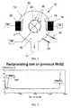
- Figures 2 and 3 show a comparison with some prior art MoS 2 coatings we have produced.
- the tests were performed using a Teer ST-2200 reciprocating tester.
- the load was 100N on a 5mm diameter WC-Co ball.
- the speed was 150mm/sec with a half period of 1 sec.
- Tests also show an improvement in cutting tool performance when they are coated with our new MoS 2 metal composite coating. Drilling tests into Al 15% Si alloys give a life of uncoated HSS drills of about 50 holes. The same HSS drills coated with our MoS 2 /Ti composite coating produced over 700 holes without failure.
- Improvements have been found in other components such as bearings, gears, automobile engine components, control valves, and other general machine parts.
- MoS 2 composite coatings which have the properties described above are believed to be new and inventive in their own right. They have a Titanium, or other metal, content.
- the other metal content may be 1 ⁇ 2%, 1%, 11 ⁇ 2, 2%, 21 ⁇ 2%, 3%, 31 ⁇ 2, 4%, 5% or higher (by percent of number of atoms in the coating layer).
- the metal content may be 30% or less, or 10% or less for MoS 2 /Ti or MoS 2 /TiN coatings.
- the coefficient of friction may be 0.05 or less, or 0.02 or less.
- the Vickers hardness may be 500HV or more.
- both magnetron electrodes at once we have a rotating component holder between them.
- a sample situated on the component holder cycles itself closer to the Titanium source, equidistant from both Titanium and MoS 2 source, closer to the MoS 2 source, equidistant from both sources, and so on.
- Figure 7 illustrates a modified UBMSIP system which has a barrier member, or dividing member, that masks one side of the component holder (at any instant) from the effects of one of the magnetron ion sources.
- the third (or further) magnetron may have a metal or carbon (or metallic semi-metal) target, or a compound (eg N,C, or O compound).
- the mask/barrier member (if provided) may define three (or more) compartments.
- Titanium we may use another reactivc metal, such as vanadium, chromium, zirconium, niobium, molybdenum, tantalum, hafnium, or tungsten or an unreactive metal, such as gold or platinum.
- reactivc metal such as vanadium, chromium, zirconium, niobium, molybdenum, tantalum, hafnium, or tungsten or an unreactive metal, such as gold or platinum.
- a non-reactive metal will not work for the ion cleaning of the system, but can be used during the deposition (in addition to the reactive metal).
- Figure 8 illustrates a MSIP system, which will usually use unbalanced magnetrons, in which there is a reactive metal target (e.g. titanium), two hexagonal layer lattice targets (e.g. MoS 2 ), and a non-reactive metal target (e.g. gold).
- a reactive metal target e.g. titanium
- two hexagonal layer lattice targets e.g. MoS 2
- a non-reactive metal target e.g. gold
- the substrate to be coated is rotated by a component holder.
- the system would preferably be a closed field system (U.K. Patent GB 2 258 343 B)
- the reactive metal target is energised in the ion cleaning operation of the system to clean the system by producing gettering ions or neutrals which mop up impurities.
- the reactive metal target is energised in the ion cleaning operation of the system to clean the system by producing gettering ions or neutrals which mop up impurities.
- Platinum is another non-reactive metal that gives good coating results.
- the carbon may be deposited as diamond-like carbon. Such coatings have also been found to have good hardness, adhesion, and low friction.
- the coatings that we make may have a stoichiometric ratio of metal to sulphur (e.g. in MoS 2 ), or a non-stoichiometric ratio.
- a stoichiometric ratio of metal to sulphur e.g. in MoS 2
- a non-stoichiometric ratio e.g. in MoS 2
- a molybdenum sulphur coating may be MoS 2 at the stoichiometric ratio or MoS x where x is above or below two.
- "X" may be about 1.5.
- X may be from 1.2 to 2.5.
- MoS 2 we mean molybdenum/sulphur composition having a hexagonal layer lattice structure (or substantially one) and having stoichiometric or non-stoichiometric composition.
- the heart of the cleaning process is that during a normal deposition sequence the surfaces of the substrates are cleaning by ion bombardment.
- the ions are produced by applying a high (typically 1000V) negative bias to the substrates in an atmosphere of argon gas at a pressure of about 0.27Pa (2 x 10 -3 torr).
- the argon ion bombardment is aided here by the operation of the second electrode which produces a flux of reactive metal into the chamber and which removes contaminants from the atmosphere in the chamber.
Landscapes
- Chemical & Material Sciences (AREA)
- Organic Chemistry (AREA)
- Engineering & Computer Science (AREA)
- Materials Engineering (AREA)
- Mechanical Engineering (AREA)
- Metallurgy (AREA)
- Chemical Kinetics & Catalysis (AREA)
- Physical Vapour Deposition (AREA)
- Inorganic Compounds Of Heavy Metals (AREA)
- Other Surface Treatments For Metallic Materials (AREA)
- Compositions Of Oxide Ceramics (AREA)
- Paints Or Removers (AREA)
- Glass Compositions (AREA)
Claims (15)
- Verfahren zum Verbessern des Aufstäubens einer Beschichtung, wie z.B. MoS2-Beschichtungen, auf ein Substrat, das die folgenden Schritte umfasst: Betreiben eines Sputterionenplattiersystems im Reinigungsbetrieb vor einem Beschichtungsbetrieb, wobei das Sputterionenplattiersystem ein erstes Magnetron mit einem Target aus MoS2 oder WS2, das auf das Substrat aufgetragen werden soll, und ein zweites Magnetron mit einem Reinigungstarget aus reaktivem Metall aufweist, ausgewählt aus Titan, Vanadium, Chrom, Zirkonium, Niob, Molybdän, Tantal, Hafnium oder Wolfram, wobei während des Reinigungsbetriebs das zweite Target erregt wird, um einen Fluss von reaktivem Reinigungsmetall zu erzeugen, das mit Verunreinigungen in der Zerstäubungskammer reagiert, um zu verhindern, dass diese während der Ionenbombardierungsreinigung des Substrats und beim Beschichtungsbetrieb eine aktive Präsenz haben, und während des Beschichtungsbetriebs das erste und das zweite Target selektiv erregt werden, und als Anfangsteil des Beschichtungsbetriebs eine Schicht des reaktiven Metalls auf das Substrat aufgebracht wird, worauf die Erregung des ersten und zweiten Targets folgt, um Material gleichzeitig auf das Substrat aufzutragen, wobei während der Reinigungs- und Beschichtungsvorgänge eine Vorspannung an das Substrat angelegt wird, wobei der Pegel der Vorspannung, die während des Reinigungsbetriebs angelegt wird, auf einen tieferen Vorspannungspegel während des Beschichtungsbetriebs reduziert wird.
- Verfahren nach Anspruch 1, bei dem wenigstens ein Teil des reaktiven Reinigungsmaterials ionisiertes Metall ist.
- Verfahren nach Anspruch 1, bei dem wenigstens ein Teil des reaktiven Reinigungsmaterials ein zerstäubtes, nichtionisiertes Metall ist.
- Verfahren nach einem der Ansprüche 1 bis 3, das in einem Magnetron-Sputterionenplattiersystem ausgeführt wird, das so gestaltet ist, dass es beim Gebrauch so arbeitet, dass der Reinigungsvorgang die Bombardierung der mit Ionen zu beschichtenden Substrate beinhaltet und auch die Bombardierung des zweiten Targets mit Ionen beinhaltet, um Metallionen oder zerstäubte Atome von dem zweiten Target in der Zerstäubungskammer zu erzeugen, wobei die Metallionen oder zerstäubten Atome die Wände der Kammer reinigen und mit Verunreinigungen in der Atmosphäre der Kammer reagieren, um die Verunreinigungen aus dem System zu beseitigen.
- Verfahren nach einem der Ansprüche 1 bis 4, bei dem Wasser und/oder Schwefel in der Zerstäubungskammeratmosphäre mit dem Metall, vorzugsweise Titan oder einem anderen reaktiven Metall, reagiert/reagieren, das von dem zweiten Target erzeugt wird, um während des Reinigungsvorgangs stabile und nicht kontaminierende Verbindungen zu bilden.
- Verfahren nach einem der Ansprüche 1 bis 5, das den Schritt des Einleitens eines weiteren Materials, das in der Beschichtung enthalten ist, in die Zerstäubungskammer während des Beschichtungsbetriebs beinhaltet.
- Verfahren nach Anspruch 6, wobei das weitere Material an diesem Punkt des Einleitens gasförmig ist und Stickstoff oder Sauerstoff oder ein Kohlenwasserstoffgas sein kann.
- Verfahren nach Anspruch 6, wobei das weitere Material ein Metall wie z.B. Titan, Vanadium, Chrom, Zirkonium, Niob, Tantal, Hafnium, Wolfram, Gold oder Platin ist.
- Verfahren nach einem der Ansprüche 1 bis 8, das ferner das Auftragen einer ersten und einer zweiten Schicht umfasst, wobei die erste Schicht entweder Titan oder ein anderes Metall oder Titannitrid oder ein anderes Metallnitrid umfasst, und wobei die zweite Schicht Molybdändisulfid oder ein anderes hexagonales Schicht-Gittermaterial; oder ein Gemisch aus Molybdändisulfid oder einem anderen hexagonalen Schicht-Gittermaterial und einem Metall; oder ein Gemisch aus Molybdändisulfid oder einem anderen hexagonalen Schicht-Gittermaterial und einem Metallnitrid umfasst.
- Verfahren nach einem der Ansprüche 1 bis 9, bei dem die Beschichtung eine Dicke zwischen 0,1 µm und 10 µm, vorzugsweise von etwa 1 µm hat.
- Artikel, beschichtet mit dem Verfahren nach einem der Ansprüche 1 bis 10, dadurch gekennzeichnet, dass die Beschichtung eine Haftungsgrenzlast Lc von 70 N oder höher, eine Vickers-Härte gemäß dem Vickers-Mikrohärtetest von 500 Hv oder mehr, einen Reibungskoeffizienten von 0,02 oder weniger, eine Verschleißbeständigkeit zum Widerstehen einer Last von 80 N und eine Lineargeschwindigkeit von 5000 mm/min unter einem Kugel-auf-Scheibe-Test unter Verwendung einer 6 mm Stahlkugel über einen Zeitraum von 3 Stunden hat.
- Artikel nach Anspruch 11, der eine Beschichtung aus einem Gemisch aus MoS2/Ti oder MoS2/TiN hat.
- Artikel nach Anspruch 12, bei dem die Beschichtung aus MoS2/Ti oder MoS2/TiN einen Ti-, TiN-Gehalt von 10% oder weniger oder 30% oder weniger gemäß dem Prozentanteil dieser Atome/Verbindungen an der Gesamtzahl der Atome der Atomprozent der Beschichtung hat.
- Artikel nach einem der Ansprüche 11 bis 13, bei dem die Grundflächen der Metallsulfidschicht parallel oder im Wesentlichen parallel zur Oberfläche des Substrats sind, das sie beschichten.
- Artikel nach einem der Ansprüche 11 bis 14, bei dem die Beschichtung keine homogene Schicht ist, sondern stattdessen Schichten unterschiedlicher Zusammensetzungen hat, die zyklisch variieren; wobei eine Art von Schicht ein hexagonales Schicht-/Gittermaterial und eine andere Art von Schicht Metall oder Halbmetall umfasst, wobei die beiden Schichtsätze abwechseln.
Applications Claiming Priority (3)
| Application Number | Priority Date | Filing Date | Title |
|---|---|---|---|
| GB9514773 | 1995-07-19 | ||
| GBGB9514773.2A GB9514773D0 (en) | 1995-07-19 | 1995-07-19 | Methods for improving the sputter deposition of metal-sulphur coatings e.g.molybdenum disulphide(MoS2) coatings |
| PCT/GB1996/001718 WO1997004142A1 (en) | 1995-07-19 | 1996-07-18 | Methods for deposition of molybdenum sulphide |
Publications (3)
| Publication Number | Publication Date |
|---|---|
| EP0842306A1 EP0842306A1 (de) | 1998-05-20 |
| EP0842306B1 EP0842306B1 (de) | 2000-01-19 |
| EP0842306B2 true EP0842306B2 (de) | 2005-06-08 |
Family
ID=10777917
Family Applications (1)
| Application Number | Title | Priority Date | Filing Date |
|---|---|---|---|
| EP96924987A Expired - Lifetime EP0842306B2 (de) | 1995-07-19 | 1996-07-18 | Verbesserungen in und betreffend Verfahren zur Verbesserung der Sputterabscheidung von Metall-Schwefel-Beschichtungen, z.B. Molybdändisulfid Beschichtungen und verbesserten Beschichtungen |
Country Status (9)
| Country | Link |
|---|---|
| EP (1) | EP0842306B2 (de) |
| JP (1) | JP3825803B2 (de) |
| AT (1) | ATE189009T1 (de) |
| AU (1) | AU6525196A (de) |
| DE (1) | DE69606307T3 (de) |
| DK (1) | DK0842306T3 (de) |
| ES (1) | ES2142079T3 (de) |
| GB (2) | GB9514773D0 (de) |
| WO (1) | WO1997004142A1 (de) |
Families Citing this family (43)
| Publication number | Priority date | Publication date | Assignee | Title |
|---|---|---|---|---|
| DE19614557A1 (de) * | 1996-04-12 | 1997-10-16 | Hauzer Holding | Bauteil mit Verschleißschutzschicht und Verfahren zu dessen Herstellung |
| DE19622823A1 (de) * | 1996-06-07 | 1997-12-11 | Widia Gmbh | Verbundwerkstoff und Verfahren zu seiner Herstellung |
| CH691776A5 (de) * | 1997-04-17 | 2001-10-15 | Bci Bloesch Corp Ag | Plasma-Beschichtungs-Verfahren und mit diesem Verfahren herstellbare Arbeitsschichten. |
| US6726993B2 (en) * | 1997-12-02 | 2004-04-27 | Teer Coatings Limited | Carbon coatings, method and apparatus for applying them, and articles bearing such coatings |
| WO1999049098A1 (de) * | 1998-03-26 | 1999-09-30 | Daimler-Benz Ag | Festschmierstoffschicht |
| EP1076728A1 (de) * | 1998-04-27 | 2001-02-21 | European Community (EC) | Reibungsarme beschichtung für ein schneidwerkzeug |
| DE19860474A1 (de) * | 1998-12-28 | 2000-07-06 | Fraunhofer Ges Forschung | Verfahren und Einrichtung zum Beschichten von Substraten mittels bipolarer Puls-Magnetron-Zerstäubung |
| US6528171B1 (en) | 1999-03-03 | 2003-03-04 | Widia Gmbh | Tool with a molybdenum sulfide containing coating and method for its production |
| DE10005612A1 (de) | 2000-02-09 | 2001-08-16 | Hauzer Techno Coating Europ B | Verfahren zur Herstellung eines Gegenstandes und Gegenstand |
| GB2360790A (en) * | 2000-03-28 | 2001-10-03 | Gehan Anil Joseph Amaratunga | Low friction coatings produced by cathodic arc evaporation |
| DE10031327A1 (de) * | 2000-07-03 | 2002-01-17 | Widia Gmbh | Schneideinsatz zum Zerspanen und Verfahren zu seiner Herstellung |
| DE10058803A1 (de) * | 2000-11-27 | 2002-06-06 | Widia Gmbh | Schneidwerkzeug zum Zerspanen |
| WO2003090319A1 (en) | 2002-04-22 | 2003-10-30 | Yazaki Corporation | Electrical connectors incorporating low friction coatings and methods for making them |
| JP4217027B2 (ja) * | 2002-04-26 | 2009-01-28 | 株式会社タンガロイ | 被覆部材 |
| US6858333B2 (en) | 2002-10-09 | 2005-02-22 | Kennametal Inc. | Tool with wear resistant low friction coating and method of making the same |
| AT6792U1 (de) * | 2002-10-14 | 2004-04-26 | Plansee Tizit Ag | Werkzeug oder bauteil mit niedrigem reibwert |
| DE10259174B4 (de) | 2002-12-18 | 2006-10-12 | Robert Bosch Gmbh | Verwendung eines tribologisch beanspruchten Bauelements |
| KR20050063463A (ko) * | 2003-12-22 | 2005-06-28 | 재단법인 포항산업과학연구원 | 윤활특성이 우수한 경질코팅 제조방법 및 경질코팅 구조 |
| US7368182B2 (en) | 2004-02-12 | 2008-05-06 | Hitachi Tool Engineering, Ltd. | Hard coating and its formation method, and hard-coated tool |
| JP4663336B2 (ja) * | 2005-01-17 | 2011-04-06 | 日立ツール株式会社 | 硬質皮膜及び硬質皮膜の製造方法 |
| JP2005249066A (ja) * | 2004-03-04 | 2005-09-15 | Yaskawa Electric Corp | 転動要素 |
| GB0410729D0 (en) * | 2004-05-14 | 2004-06-16 | Teer Coatings Ltd | Coating with hard wear and non-stick characteristics |
| EP1614655B2 (de) | 2004-06-18 | 2018-08-08 | Hitachi Tool Engineering Ltd. | Hartbeschichtung und Herstellungsverfahren dazu |
| KR20070049679A (ko) * | 2004-09-30 | 2007-05-11 | 티에치케이 가부시끼가이샤 | 구름 안내 장치 |
| JP4771202B2 (ja) | 2005-04-13 | 2011-09-14 | 日立金属株式会社 | 密着性と摺動特性に優れた複合皮膜およびその製造方法 |
| JP2007217768A (ja) * | 2006-02-17 | 2007-08-30 | Toyota Industries Corp | 圧縮機用摺動部品の製造方法および圧縮機用摺動部品 |
| JP2007217766A (ja) * | 2006-02-17 | 2007-08-30 | Toyota Industries Corp | 低摩擦複合膜の成膜方法および低摩擦摺動部材 |
| EP2072637B1 (de) * | 2007-12-21 | 2018-08-15 | Sandvik Intellectual Property AB | Beschichtetes Schneidwerkzeug und Verfahren zum Herstellen |
| DE102008062332A1 (de) | 2008-12-15 | 2010-06-17 | Gühring Ohg | Vorrichtung zur Oberflächenbehandlung und/oder -beschichtung von Substratkomponenten |
| CH705029A1 (de) * | 2011-05-27 | 2012-11-30 | Bloesch W Ag | Beschichtetes Holzbearbeitungswerkzeug. |
| KR20130060544A (ko) | 2011-11-30 | 2013-06-10 | 현대자동차주식회사 | 나노멀티레이어 코팅층 형성방법 및 형성장치 |
| JP2014034721A (ja) * | 2012-08-09 | 2014-02-24 | Mitsubishi Materials Corp | スパッタリングターゲット及びその製造方法 |
| CN103805949B (zh) * | 2014-02-17 | 2016-07-27 | 武汉大学 | 二硫化钼自润滑复合涂层及覆有该复合涂层的活塞环 |
| CN104120389B (zh) * | 2014-08-04 | 2016-08-24 | 上海和辉光电有限公司 | 镀膜设备 |
| GB201507524D0 (en) * | 2015-05-01 | 2015-06-17 | Teer Coatings Ltd | Improvements to molybdenum containing coatings |
| CN108998759B (zh) * | 2018-08-08 | 2020-10-09 | 电子科技大学 | 一种提高多层二硫化钼薄膜间接带隙发光性能的方法 |
| TW202122909A (zh) * | 2019-10-25 | 2021-06-16 | 美商應用材料股份有限公司 | 減少極紫外遮罩毛坯缺陷之方法 |
| CN111172498A (zh) | 2020-01-19 | 2020-05-19 | 中国科学院宁波材料技术与工程研究所 | 二硫化钼/二硫化钨多层掺钽薄膜及其制备方法与应用 |
| CN115323326B (zh) * | 2022-08-17 | 2023-11-24 | 中国科学院兰州化学物理研究所 | 一种耐空间原子氧辐照的长寿命二硫化钼基复合薄膜的制备方法和应用 |
| CN116497457B (zh) | 2023-05-29 | 2023-09-12 | 中国科学院宁波材料技术与工程研究所 | 一种低摩擦长寿命的超晶格复合涂层及其制备方法与用途 |
| CN117089815B (zh) * | 2023-08-22 | 2025-12-02 | 吉林大学 | 一种低摩耐磨TiNbMoTaCr/MoS2纳米多层膜及其制备方法和应用 |
| CN117265477A (zh) * | 2023-09-28 | 2023-12-22 | 台州学院 | 一种WS2固体润滑薄膜的HiPIMS制备方法 |
| CN118703958B (zh) * | 2024-08-28 | 2024-11-01 | 广东欧欧优家居有限公司 | 不锈钢厨具的表面处理工艺 |
Family Cites Families (22)
| Publication number | Priority date | Publication date | Assignee | Title |
|---|---|---|---|---|
| US4424101A (en) * | 1980-11-06 | 1984-01-03 | The Perkin-Elmer Corp. | Method of depositing doped refractory metal silicides using DC magnetron/RF diode mode co-sputtering techniques |
| DD202898A1 (de) * | 1981-11-02 | 1983-10-05 | Ruhla Uhren Veb K | Hartstoff und festkoerperschmierstoffschichtsystem |
| US4591418A (en) * | 1984-10-26 | 1986-05-27 | The Parker Pen Company | Microlaminated coating |
| DE3569265D1 (en) * | 1985-01-17 | 1989-05-11 | Ibm Deutschland | Process for the production of low-resistance contacts |
| JPS61238958A (ja) * | 1985-04-15 | 1986-10-24 | Hitachi Ltd | 複合薄膜形成法及び装置 |
| US4731172A (en) * | 1985-04-18 | 1988-03-15 | Matsushita Electric Industrial Co., Ltd. | Method for sputtering multi-component thin-film |
| DE3516933A1 (de) * | 1985-05-10 | 1986-11-13 | Deutsche Forschungs- und Versuchsanstalt für Luft- und Raumfahrt e.V., 5300 Bonn | Verfahren zum aufbringen einer mos(pfeil abwaerts)2(pfeil abwaerts)-beschichtung auf ein substrat |
| FR2586430B1 (fr) * | 1985-08-26 | 1992-10-30 | Preci Coat Sa | Procede de traitement pour diminuer l'usure et le frotttement d'objets et objets traites selon ce procede |
| GB8629409D0 (en) * | 1986-12-09 | 1987-01-21 | Evans B L | Multilayered structures |
| JPH02217467A (ja) * | 1989-02-17 | 1990-08-30 | Pioneer Electron Corp | 対向ターゲット型スパッタリング装置 |
| US5002798A (en) * | 1989-04-10 | 1991-03-26 | University Of Dayton | Method for forming thin solid lubricious films and film articles made thereby |
| JPH0314227A (ja) * | 1989-06-13 | 1991-01-22 | Sharp Corp | 半導体装置の製造方法 |
| EP0409451A1 (de) * | 1989-07-18 | 1991-01-23 | Optical Coating Laboratory, Inc. | Verfahren zum Auftragen von dünnen optischen Schichten auf sowohl flachen als auch nicht flachen Substraten |
| JPH0397855A (ja) * | 1989-09-07 | 1991-04-23 | Shimadzu Corp | スパッタリング装置 |
| GB9006073D0 (en) * | 1990-03-17 | 1990-05-16 | D G Teer Coating Services Limi | Magnetron sputter ion plating |
| AU8320491A (en) * | 1990-07-06 | 1992-02-04 | Boc Group, Inc., The | Method and apparatus for co-sputtering and cross-sputtering homogeneous films |
| DE4038497C1 (de) * | 1990-12-03 | 1992-02-20 | Leybold Ag, 6450 Hanau, De | |
| US5268216A (en) * | 1990-12-21 | 1993-12-07 | Ovonic Synthetic Materials Company, Inc. | Multilayer solid lubricant composite structures and method of making same |
| CA2078245A1 (en) * | 1991-09-23 | 1993-03-24 | Roland Dubach | Machining tools |
| JPH05271928A (ja) * | 1992-03-23 | 1993-10-19 | Hitachi Ltd | 摺動部材とその製法並びにその用途 |
| US5282985A (en) * | 1993-06-24 | 1994-02-01 | The United States Of America As Represented By The Secretary Of The Air Force | Lubricant coatings |
| DE4414051C1 (de) * | 1994-04-22 | 1995-07-06 | Dresden Ev Inst Festkoerper | Reibarmer Schichtverbund für Bauteile aus metallischen Werkstoffen |
-
1995
- 1995-07-19 GB GBGB9514773.2A patent/GB9514773D0/en active Pending
-
1996
- 1996-07-18 JP JP50643197A patent/JP3825803B2/ja not_active Expired - Lifetime
- 1996-07-18 EP EP96924987A patent/EP0842306B2/de not_active Expired - Lifetime
- 1996-07-18 GB GB9615137A patent/GB2303380B/en not_active Expired - Lifetime
- 1996-07-18 ES ES96924987T patent/ES2142079T3/es not_active Expired - Lifetime
- 1996-07-18 WO PCT/GB1996/001718 patent/WO1997004142A1/en not_active Ceased
- 1996-07-18 AT AT96924987T patent/ATE189009T1/de not_active IP Right Cessation
- 1996-07-18 AU AU65251/96A patent/AU6525196A/en not_active Abandoned
- 1996-07-18 DE DE69606307T patent/DE69606307T3/de not_active Expired - Lifetime
- 1996-07-18 DK DK96924987T patent/DK0842306T3/da active
Non-Patent Citations (2)
| Title |
|---|
| Adibi et al., "Design and characterization of a compact two-target ultrahigh vacuum magnetron sputter deposition system: Application to the growth of epitaxial Ti1-xAIxN alloys and TiN/Ti1-xAIxN superlattices", Journal of Vacuum Science and Technology, Jan/Feb 1993, pages 136 to 142 † |
| Bernard C. Stupp, 1981, "Synergistic Effects of Metals co-sputtered with MoS2" † |
Also Published As
| Publication number | Publication date |
|---|---|
| GB2303380B (en) | 1999-06-30 |
| DE69606307T2 (de) | 2000-07-20 |
| ATE189009T1 (de) | 2000-02-15 |
| GB2303380A (en) | 1997-02-19 |
| ES2142079T3 (es) | 2000-04-01 |
| DE69606307T3 (de) | 2006-04-13 |
| EP0842306B1 (de) | 2000-01-19 |
| AU6525196A (en) | 1997-02-18 |
| DK0842306T3 (da) | 2000-05-08 |
| WO1997004142A1 (en) | 1997-02-06 |
| GB9615137D0 (en) | 1996-09-04 |
| JP3825803B2 (ja) | 2006-09-27 |
| DE69606307D1 (de) | 2000-02-24 |
| EP0842306A1 (de) | 1998-05-20 |
| JPH11509580A (ja) | 1999-08-24 |
| GB9514773D0 (en) | 1995-09-20 |
Similar Documents
| Publication | Publication Date | Title |
|---|---|---|
| EP0842306B2 (de) | Verbesserungen in und betreffend Verfahren zur Verbesserung der Sputterabscheidung von Metall-Schwefel-Beschichtungen, z.B. Molybdändisulfid Beschichtungen und verbesserten Beschichtungen | |
| US6423419B1 (en) | Molybdenum-sulphur coatings | |
| Kelly et al. | Magnetron sputtering: a review of recent developments and applications | |
| Alami et al. | High power pulsed magnetron sputtering: Fundamentals and applications | |
| US8173278B2 (en) | Coated body | |
| Randhawa et al. | A review of cathodic arc plasma deposition processes and their applications | |
| US6827976B2 (en) | Method to increase wear resistance of a tool or other machine component | |
| EP2017366B1 (de) | Verfahren zur Herstellung einer harten Beschichtung für ein Metallsubstrat und beschichtetes Substrat | |
| CN101463461B (zh) | 制造涂层切削刀具的方法及根据该方法制成的切削刀具 | |
| EP1874981B1 (de) | Pvd-beschichtetes substrat | |
| Bunshah | Processes of the activated reactive evaporation type and their tribological applications | |
| US9540726B2 (en) | Drill having a coating | |
| EP2201154B1 (de) | Verfahren zur herstellung einer schicht durch bogenverdampfung auf keramischen kathoden | |
| CN1304457A (zh) | Pvd法涂覆的切削刀具及其制备方法 | |
| KR20230082022A (ko) | HiPIMS에 의해 향상된 접착력을 갖는 경질 탄소 코팅 및 그 제조방법 | |
| JPH0588310B2 (de) | ||
| JP3460288B2 (ja) | 耐摩耗性に優れた表面被覆部材 | |
| CN111945111A (zh) | 一种沉积在立方氮化硼刀具表面的复合涂层及沉积方法 | |
| KR102074469B1 (ko) | 포밍 치형공구용 다층나노 경질 코팅막 | |
| KR20100034013A (ko) | 다층 금속 산화물 코팅을 구비한 공구 및 코팅된 공구의 제조 방법 | |
| Erkens | New approaches to plasma enhanced sputtering of advanced hard coatings | |
| JPH04297568A (ja) | 耐摩耗性のすぐれた表面被覆部材及び皮膜形成方法 | |
| KR20050063463A (ko) | 윤활특성이 우수한 경질코팅 제조방법 및 경질코팅 구조 | |
| WO2002070776A1 (en) | Deposition process | |
| KR100305885B1 (ko) | 절삭공구/내마모성 공구용 표면 피복 경질합금 |
Legal Events
| Date | Code | Title | Description |
|---|---|---|---|
| PUAI | Public reference made under article 153(3) epc to a published international application that has entered the european phase |
Free format text: ORIGINAL CODE: 0009012 |
|
| 17P | Request for examination filed |
Effective date: 19980204 |
|
| AK | Designated contracting states |
Kind code of ref document: A1 Designated state(s): AT BE CH DE DK ES FI FR GR IE IT LI LU MC NL PT SE |
|
| 17Q | First examination report despatched |
Effective date: 19980622 |
|
| GRAG | Despatch of communication of intention to grant |
Free format text: ORIGINAL CODE: EPIDOS AGRA |
|
| GRAG | Despatch of communication of intention to grant |
Free format text: ORIGINAL CODE: EPIDOS AGRA |
|
| RBV | Designated contracting states (corrected) |
Designated state(s): AT BE CH DE DK ES FI FR GR IE IT LI LU MC NL PT SE |
|
| GRAG | Despatch of communication of intention to grant |
Free format text: ORIGINAL CODE: EPIDOS AGRA |
|
| GRAH | Despatch of communication of intention to grant a patent |
Free format text: ORIGINAL CODE: EPIDOS IGRA |
|
| GRAH | Despatch of communication of intention to grant a patent |
Free format text: ORIGINAL CODE: EPIDOS IGRA |
|
| GRAA | (expected) grant |
Free format text: ORIGINAL CODE: 0009210 |
|
| AK | Designated contracting states |
Kind code of ref document: B1 Designated state(s): AT BE CH DE DK ES FI FR GR IE IT LI LU MC NL PT SE |
|
| ITF | It: translation for a ep patent filed | ||
| PG25 | Lapsed in a contracting state [announced via postgrant information from national office to epo] |
Ref country code: GR Free format text: LAPSE BECAUSE OF NON-PAYMENT OF DUE FEES Effective date: 20000119 Ref country code: ES Free format text: LAPSE BECAUSE OF FAILURE TO SUBMIT A TRANSLATION OF THE DESCRIPTION OR TO PAY THE FEE WITHIN THE PRESCRIBED TIME-LIMIT Effective date: 20000119 |
|
| REF | Corresponds to: |
Ref document number: 189009 Country of ref document: AT Date of ref document: 20000215 Kind code of ref document: T |
|
| REG | Reference to a national code |
Ref country code: CH Ref legal event code: EP |
|
| REF | Corresponds to: |
Ref document number: 69606307 Country of ref document: DE Date of ref document: 20000224 |
|
| REG | Reference to a national code |
Ref country code: CH Ref legal event code: NV Representative=s name: NOVAPAT INTERNATIONAL S.A. |
|
| ET | Fr: translation filed | ||
| REG | Reference to a national code |
Ref country code: IE Ref legal event code: FG4D |
|
| REG | Reference to a national code |
Ref country code: ES Ref legal event code: FG2A Ref document number: 2142079 Country of ref document: ES Kind code of ref document: T3 |
|
| PG25 | Lapsed in a contracting state [announced via postgrant information from national office to epo] |
Ref country code: PT Free format text: LAPSE BECAUSE OF FAILURE TO SUBMIT A TRANSLATION OF THE DESCRIPTION OR TO PAY THE FEE WITHIN THE PRESCRIBED TIME-LIMIT Effective date: 20000419 |
|
| REG | Reference to a national code |
Ref country code: DK Ref legal event code: T3 |
|
| PG25 | Lapsed in a contracting state [announced via postgrant information from national office to epo] |
Ref country code: LU Free format text: LAPSE BECAUSE OF NON-PAYMENT OF DUE FEES Effective date: 20000718 |
|
| PG25 | Lapsed in a contracting state [announced via postgrant information from national office to epo] |
Ref country code: MC Free format text: THE PATENT HAS BEEN ANNULLED BY A DECISION OF A NATIONAL AUTHORITY Effective date: 20000731 |
|
| PGFP | Annual fee paid to national office [announced via postgrant information from national office to epo] |
Ref country code: IE Payment date: 20000929 Year of fee payment: 5 |
|
| PLBQ | Unpublished change to opponent data |
Free format text: ORIGINAL CODE: EPIDOS OPPO |
|
| PLBI | Opposition filed |
Free format text: ORIGINAL CODE: 0009260 |
|
| 26 | Opposition filed |
Opponent name: HAUZER INDUSTRIES B.V. Effective date: 20001019 Opponent name: PLATIT AG Effective date: 20001019 |
|
| PLBF | Reply of patent proprietor to notice(s) of opposition |
Free format text: ORIGINAL CODE: EPIDOS OBSO |
|
| NLR1 | Nl: opposition has been filed with the epo |
Opponent name: HAUZER INDUSTRIES B.V. Opponent name: PLATIT AG |
|
| PLBF | Reply of patent proprietor to notice(s) of opposition |
Free format text: ORIGINAL CODE: EPIDOS OBSO |
|
| PLBF | Reply of patent proprietor to notice(s) of opposition |
Free format text: ORIGINAL CODE: EPIDOS OBSO |
|
| PG25 | Lapsed in a contracting state [announced via postgrant information from national office to epo] |
Ref country code: IE Free format text: LAPSE BECAUSE OF NON-PAYMENT OF DUE FEES Effective date: 20010718 |
|
| PLBF | Reply of patent proprietor to notice(s) of opposition |
Free format text: ORIGINAL CODE: EPIDOS OBSO |
|
| REG | Reference to a national code |
Ref country code: IE Ref legal event code: MM4A |
|
| REG | Reference to a national code |
Ref country code: CH Ref legal event code: NV Representative=s name: ABREMA AGENCE BREVETS ET MARQUES GANGUILLET & HUMP |
|
| PLBP | Opposition withdrawn |
Free format text: ORIGINAL CODE: 0009264 |
|
| RDAH | Patent revoked |
Free format text: ORIGINAL CODE: EPIDOS REVO |
|
| RTI2 | Title (correction) |
Free format text: IMPROVEMENTS IN AND RELATING TO METHODS FOR IMPROVING THE SPUTTER DESPOSITION OF METAL-SULPHUR COATINGS, E.G. MOLYBDENUM DISULPHIDE COATINGS AND TO IMPROVED COATINGS |
|
| RTI2 | Title (correction) |
Free format text: IMPROVEMENTS IN AND RELATING TO METHODS FOR IMPROVING THE SPUTTER DESPOSITION OF METAL-SULPHUR COATINGS, E.G. MOLYBDENUM DISULPHIDE COATINGS AND TO IMPROVED COATINGS |
|
| APAC | Appeal dossier modified |
Free format text: ORIGINAL CODE: EPIDOS NOAPO |
|
| APAC | Appeal dossier modified |
Free format text: ORIGINAL CODE: EPIDOS NOAPO |
|
| PGFP | Annual fee paid to national office [announced via postgrant information from national office to epo] |
Ref country code: BE Payment date: 20030602 Year of fee payment: 8 |
|
| PGFP | Annual fee paid to national office [announced via postgrant information from national office to epo] |
Ref country code: ES Payment date: 20030604 Year of fee payment: 8 |
|
| PGFP | Annual fee paid to national office [announced via postgrant information from national office to epo] |
Ref country code: DK Payment date: 20030702 Year of fee payment: 8 |
|
| PGFP | Annual fee paid to national office [announced via postgrant information from national office to epo] |
Ref country code: FI Payment date: 20030709 Year of fee payment: 8 |
|
| PGFP | Annual fee paid to national office [announced via postgrant information from national office to epo] |
Ref country code: AT Payment date: 20030724 Year of fee payment: 8 |
|
| PG25 | Lapsed in a contracting state [announced via postgrant information from national office to epo] |
Ref country code: FI Free format text: LAPSE BECAUSE OF NON-PAYMENT OF DUE FEES Effective date: 20040718 Ref country code: AT Free format text: LAPSE BECAUSE OF NON-PAYMENT OF DUE FEES Effective date: 20040718 |
|
| PG25 | Lapsed in a contracting state [announced via postgrant information from national office to epo] |
Ref country code: BE Free format text: LAPSE BECAUSE OF NON-PAYMENT OF DUE FEES Effective date: 20040731 |
|
| PG25 | Lapsed in a contracting state [announced via postgrant information from national office to epo] |
Ref country code: DK Free format text: LAPSE BECAUSE OF NON-PAYMENT OF DUE FEES Effective date: 20040802 |
|
| APBU | Appeal procedure closed |
Free format text: ORIGINAL CODE: EPIDOSNNOA9O |
|
| BERE | Be: lapsed |
Owner name: *TEER COATINGS LTD Effective date: 20040731 |
|
| REG | Reference to a national code |
Ref country code: DK Ref legal event code: EBP |
|
| PUAH | Patent maintained in amended form |
Free format text: ORIGINAL CODE: 0009272 |
|
| STAA | Information on the status of an ep patent application or granted ep patent |
Free format text: STATUS: PATENT MAINTAINED AS AMENDED |
|
| 27A | Patent maintained in amended form |
Effective date: 20050608 |
|
| AK | Designated contracting states |
Kind code of ref document: B2 Designated state(s): AT BE CH DE DK ES FI FR GR IE IT LI LU MC NL PT SE |
|
| REG | Reference to a national code |
Ref country code: CH Ref legal event code: AEN Free format text: AUFRECHTERHALTUNG DES PATENTES IN GEAENDERTER FORM |
|
| REG | Reference to a national code |
Ref country code: SE Ref legal event code: RPEO |
|
| NLR2 | Nl: decision of opposition |
Effective date: 20050608 |
|
| APAH | Appeal reference modified |
Free format text: ORIGINAL CODE: EPIDOSCREFNO |
|
| NLR3 | Nl: receipt of modified translations in the netherlands language after an opposition procedure | ||
| ET3 | Fr: translation filed ** decision concerning opposition | ||
| BERE | Be: lapsed |
Owner name: *TEER COATINGS LTD Effective date: 20040731 |
|
| PGFP | Annual fee paid to national office [announced via postgrant information from national office to epo] |
Ref country code: CH Payment date: 20130517 Year of fee payment: 18 Ref country code: SE Payment date: 20130521 Year of fee payment: 18 |
|
| PGFP | Annual fee paid to national office [announced via postgrant information from national office to epo] |
Ref country code: NL Payment date: 20130517 Year of fee payment: 18 |
|
| PGFP | Annual fee paid to national office [announced via postgrant information from national office to epo] |
Ref country code: IT Payment date: 20130718 Year of fee payment: 18 |
|
| REG | Reference to a national code |
Ref country code: NL Ref legal event code: V1 Effective date: 20150201 |
|
| REG | Reference to a national code |
Ref country code: CH Ref legal event code: PL |
|
| REG | Reference to a national code |
Ref country code: SE Ref legal event code: EUG |
|
| PG25 | Lapsed in a contracting state [announced via postgrant information from national office to epo] |
Ref country code: NL Free format text: LAPSE BECAUSE OF NON-PAYMENT OF DUE FEES Effective date: 20150201 |
|
| PG25 | Lapsed in a contracting state [announced via postgrant information from national office to epo] |
Ref country code: IT Free format text: LAPSE BECAUSE OF NON-PAYMENT OF DUE FEES Effective date: 20140718 Ref country code: CH Free format text: LAPSE BECAUSE OF NON-PAYMENT OF DUE FEES Effective date: 20140731 Ref country code: LI Free format text: LAPSE BECAUSE OF NON-PAYMENT OF DUE FEES Effective date: 20140731 |
|
| PG25 | Lapsed in a contracting state [announced via postgrant information from national office to epo] |
Ref country code: SE Free format text: LAPSE BECAUSE OF NON-PAYMENT OF DUE FEES Effective date: 20140719 |
|
| REG | Reference to a national code |
Ref country code: FR Ref legal event code: PLFP Year of fee payment: 20 |
|
| PGFP | Annual fee paid to national office [announced via postgrant information from national office to epo] |
Ref country code: DE Payment date: 20150605 Year of fee payment: 20 |
|
| PGFP | Annual fee paid to national office [announced via postgrant information from national office to epo] |
Ref country code: FR Payment date: 20150605 Year of fee payment: 20 |
|
| REG | Reference to a national code |
Ref country code: DE Ref legal event code: R071 Ref document number: 69606307 Country of ref document: DE |