EP0842477B1 - Systeme et procede de gestion d'informations techniques - Google Patents
Systeme et procede de gestion d'informations techniques Download PDFInfo
- Publication number
- EP0842477B1 EP0842477B1 EP97915654A EP97915654A EP0842477B1 EP 0842477 B1 EP0842477 B1 EP 0842477B1 EP 97915654 A EP97915654 A EP 97915654A EP 97915654 A EP97915654 A EP 97915654A EP 0842477 B1 EP0842477 B1 EP 0842477B1
- Authority
- EP
- European Patent Office
- Prior art keywords
- diagrams
- information
- items
- diagram
- hardware
- Prior art date
- Legal status (The legal status is an assumption and is not a legal conclusion. Google has not performed a legal analysis and makes no representation as to the accuracy of the status listed.)
- Expired - Lifetime
Links
Images


Classifications
-
- G—PHYSICS
- G06—COMPUTING OR CALCULATING; COUNTING
- G06F—ELECTRIC DIGITAL DATA PROCESSING
- G06F40/00—Handling natural language data
- G06F40/10—Text processing
- G06F40/12—Use of codes for handling textual entities
- G06F40/131—Fragmentation of text files, e.g. creating reusable text-blocks; Linking to fragments, e.g. using XInclude; Namespaces
-
- G—PHYSICS
- G06—COMPUTING OR CALCULATING; COUNTING
- G06F—ELECTRIC DIGITAL DATA PROCESSING
- G06F16/00—Information retrieval; Database structures therefor; File system structures therefor
- G06F16/30—Information retrieval; Database structures therefor; File system structures therefor of unstructured textual data
- G06F16/34—Browsing; Visualisation therefor
-
- G—PHYSICS
- G06—COMPUTING OR CALCULATING; COUNTING
- G06F—ELECTRIC DIGITAL DATA PROCESSING
- G06F30/00—Computer-aided design [CAD]
- G06F30/30—Circuit design
-
- Y—GENERAL TAGGING OF NEW TECHNOLOGICAL DEVELOPMENTS; GENERAL TAGGING OF CROSS-SECTIONAL TECHNOLOGIES SPANNING OVER SEVERAL SECTIONS OF THE IPC; TECHNICAL SUBJECTS COVERED BY FORMER USPC CROSS-REFERENCE ART COLLECTIONS [XRACs] AND DIGESTS
- Y10—TECHNICAL SUBJECTS COVERED BY FORMER USPC
- Y10S—TECHNICAL SUBJECTS COVERED BY FORMER USPC CROSS-REFERENCE ART COLLECTIONS [XRACs] AND DIGESTS
- Y10S707/00—Data processing: database and file management or data structures
- Y10S707/99941—Database schema or data structure
- Y10S707/99943—Generating database or data structure, e.g. via user interface
-
- Y—GENERAL TAGGING OF NEW TECHNOLOGICAL DEVELOPMENTS; GENERAL TAGGING OF CROSS-SECTIONAL TECHNOLOGIES SPANNING OVER SEVERAL SECTIONS OF THE IPC; TECHNICAL SUBJECTS COVERED BY FORMER USPC CROSS-REFERENCE ART COLLECTIONS [XRACs] AND DIGESTS
- Y10—TECHNICAL SUBJECTS COVERED BY FORMER USPC
- Y10S—TECHNICAL SUBJECTS COVERED BY FORMER USPC CROSS-REFERENCE ART COLLECTIONS [XRACs] AND DIGESTS
- Y10S707/00—Data processing: database and file management or data structures
- Y10S707/99941—Database schema or data structure
- Y10S707/99944—Object-oriented database structure
- Y10S707/99945—Object-oriented database structure processing
Definitions
- This invention relates to a system for accessing and using technical data, comprising:
- This invention further relates to a method of arranging a computer memory to contain technical data including diagrams having a plurality of items on each diagram, comprising the steps of:
- a diagram is a visualization of a software object.
- the software object is a model of an abstract or physical real world object.
- the real world objects may be divided into object types.
- the software implementation of an object type is known as an object class.
- Each object class has a set of attributes of which the values collectively describe features of interest of the real world object that it models.
- Each object class can have a different graphical visualization like a box, a circle or an ellipse on the diagram.
- Two of the attributes can be the x and y coordinates of the object class on the diagram.
- the object classes are connected through flow lines (as used in flow-chart diagrams) to indicate the flow of information between the object classes.
- the diagrams reflect an object oriented software model of physical real world objects.
- An object of this invention is to provide for easy access to and flexible use of technical information, such as contained in service manuals, and to place such technical information in computer format that is easily accessible. Yet another object of this invention is to provide for storing, on one computer, technical information from a plurality of manufacturers respecting various types of product. Still another object of this invention is to provide for linking together various distinct aspects of technical information. A further object of this invention is to enhance a technician's productivity and troubleshooting capabilities while also reducing the need for printing, mailing, storing, and updating printed manuals.
- the invention achieves these objects by providing a system for accessing and using technical data, according to the preamble, wherein the system is characterized in that said technical data are technical hardware related data such as hardware service data, said items are hardware items, and said diagrams are hardware diagrams: and that the system further comprises a main database comprising said descriptive information; a location database comprising said diagram location; a main stack comprising said plurality of diagrams; an interface device for interfacing with said control module to locate a selected one of said hardware items in said data set on one of said hardware diagrams or through one of said identifying information or through said descriptive information and wherein said control module automatically accesses the other said identifying or descriptive information and any of said hardware diagrams containing said selected hardware item through said linking information in response to said interface device; and to automatically interact with an external database to extract additional information for the located selected one of said hardware items.
- said technical data are technical hardware related data such as hardware service data
- said items are hardware items
- said diagrams are hardware diagrams: and that the system further comprises a main database compris
- the data set includes at least two types of written information, such as information for identifying each of a number of items or components, and information for describing each of the items or components.
- the data set also includes technical diagrams illustrating selected ones of the items or components, each item on each diagram generally having a specified diagram location.
- the data set further includes linking information for linking the identifying information, the descriptive information and the diagram location for each item or component.
- the system also comprises a control module for controlling access to the data set.
- the control module has an associated interface device by which a user interfaces with the control module to locate a selected item in the data set, e.g., by reviewing the diagrams or choosing access through the identifying information or the descriptive information.
- the control module provides for automatic access to all information, including diagrams, in response to commands generated by a user.
- the linking information enables the control module to move between and among the various aspects of the technical data for each component.
- a significant advantage provided by this invention is that manuals of various manufacturers and product types such as TVs, VCRs, and other consumer electronics, is stored in and accessed from a single computer and all technical information from these manuals is stored in a substantially uniform data structure regardless of the original printed format. Accordingly, the service technician can readily locate and use the needed manual and can do so without substantial effort to shift mindset or to understand the completely different styles present the various manufacturers' printed service manuals. This significantly improves the usability of technical service information.
- the invention has the capability to readily associate related items of technical information.
- separate documents have been used to provide related technical information that may apply to one or more different products, which information may span years of time.
- a technician would associate such documents, generally by physically consolidating.
- This invention enables the service manual developer and technician to associate related technical informations, such as known fault, training and troubleshooting informations, to the implicated service manual for each specific product, or part thereof.
- the technician is thereby provided with a single program through which all technical information pertaining to the product is instantly accessible, regardless of product brand or type. The result is a significant time saving by providing clear, useable access to all known data.
- the invention facilitates remote transfer of service information through compression.
- graphics preferably are compressed using the TIFF Group IV standard, while text preferably is compressed using Compression Plus, which is available from MicroHelp of Marietta, GA. As any text or graphic is displayed, that information must first be decompressed.
- a program designed according to the invention preferably operates in a Windows environment (Windows is a trademark of Microsoft Corporation).
- the program may include the ability to display and manipulate graphics and written text. Minimum requirements are Windows 3. I or a more recent version, and a 386 PC with at least 4 Mb RAM and a VGA.
- the program preferably is operated from the hard drive on the computer.
- the program preferably includes hyperlinks, such as those which provide access to on-line information, including information available via the Internet.
- a program designed according to this invention preferably operates from a main graphic program that serves as a control module, such program being referred to as a graphics engine.
- a graphics engine is commercially available from AccuSoft Corporation (MASS, USA) under the AccuSoft IFL (Image Format Library) brand.
- the graphics engine (i) provides for using diagrams in many different formats, (ii) provides for using highly compressed graphics files and, thereby, reducing the size of the complete manual so as to enhance both storage on available hard drive systems and-practical distribution via electronic means (e.g bulletin board systems and Internet applications), and (iii) enhances program speed so that the time required for a technician to locate and display a schematic using the computer is less than the time required to locate and open the paper-equivalent schematic.
- the ability of the program to make use of single bit diagrams greatly enhances all of the processes described above, e.g., speed size and usability.
- the second main component of the program is a set of database files, which facilitate the user's access to the contained data, define relationships between associated text and graphics files, and effectively create links to all selected data.
- these database files contain descriptions of all information normally associated with a printed service manual and the pointers to related graphics files (stacks) and text files.
- Figure 1 schematically illustrates the main data set 20 of a typical consumer electronics service manual.
- Multiple service manuals may be stored on one computer.
- the directory structure of the hard drive segments the data into manufacturers and manuals, respectively: each manufacturer is represented by a unique subdirectory under which reside unique subdirectories for each individual service manual, and these service manual directories preferably are organized by generic categories, e.g., audio, video, and appliances.
- the data in a manufacturer's subdirectory is specific to that manufacturer and preferably covers multiple manuals for that manufacturer.
- the data set contained in any one service manual subdirectory is preferably applicable only to the specific service manual for which the subdirectory is named.
- main stack 22 contains all schematics, circuit board diagrams an interconnect diagrams for servicing any specific product.
- the associated main database 23 contains additional information, including text descriptions of the diagrams within main stack 22, and provides various functions, including identifying each diagram stack position, identifying the related circuit board diagram, defining the grid size (x,y) for component locations on the diagrams, and setting stop points for multi-sectioned diagrams.
- the main stack 22 is used by database files in the main data set 20 to display information, including component locations described in a "component” database, circuit location described in a “circuit” database 24, fault locations defined in a "known fault” and/or troubleshooting database 25 and waveforms as described in a waveform database 26.
- the circuit and component databases preferably are placed within a collection of locations databases 24.
- the databases including those described above, generally comprise a text description of a function (component, circuit etc), a stack position to indicate a specific diagram, the (x,y) position of the diagram on the screen and a zoom factor used to define the "view" the user sees.
- the known fault database contains both a text description of a fault and a direction to solve it.
- a product requiring service is identified by the technician as being of a particular manufacturer.
- the technician opens the program and selects the appropriate manufacturer from a list provided by a manufacturer database 40, e.g., a subdirectory for that manufacturer.
- the database 40 contains the path for that manufacturer's subdirectory and the paths to any external programs (preferably a maximum of three) and the external programs' executable file names.
- the technician then further defines the product being serviced.
- the technician can select either a generic product category, such as video, audio, appliance or the like, or a model number, or a chassis number (electrical package) if known, or both.
- a generic product category such as video, audio, appliance or the like
- a model number such as a chassis number (electrical package) if known, or both.
- the selection is made from an appropriate database, such as a model/chassis database 41/42, located in an applicable manufacturer's subdirectory.
- This database 41/42 preferably contains cross references between the manufacturer's model numbers, service manuals numbers, and chassis numbers. Selecting the appropriate model number, for example, provides to the technician access to all data required to repair the specific product being serviced.
- the technician accesses information associated with the product by navigating through additional databases. In doing so, the technician needs no knowledge about the product. For example, the technician is enabled to identify and view any or more of major assemblies, or subassemblies, or circuits, or components, or component physical locations, or signal flows, values and waveforms, or fault information, or adjustment procedure (electrical and mechanical), or parts information, or procedures to determine what is defective about the product, or any other information for the product, or its problems, parts or otherwise. Information preferably is random accessible via any of various mechanisms, including, for example, menus, hotkeys and a pointing device, such as a mouse.
- the user is enabled to access information developed, e.g., by the user, and previously recorded locally, e.g. by the user in a rich text format, or a database format.
- the technician preferably is provided with a series of options from which to choose, the options being presented via a screen display of texts, icons, menus, or otherwise.
- the options enable the technician to locate a diagram by selected circuit (via database 46), by a selected component (via database 48), by a described fault condition (via database 50), by a diagram description (via database 52), or by selected printed circuit board (via database 54), or by combinations of the above.
- the technician is also enabled to gather information about a particular part by its component number (via database 56), assembly and disassembly procedures (via database 58), technical training information (via database 60), troubleshooting procedures (via database 62), adjustments (via database 64), or general information (via database 66).
- component number via database 56
- assembly and disassembly procedures via database 58
- technical training information via database 60
- troubleshooting procedures via database 62
- adjustments via database 64
- general information via database 66.
- the various databases are part of data set 20 and comprise stacks that include pages of graphic files. Each such page individually accessible, through one or more of the databases of the data set 20.
- the main database 23 contains the descriptions and pointers for all diagrams (pages) of the main stack 22 which may include schematics, circuit board layouts and interconnect diagrams for that product. Any of the pages can be displayed by selecting from a list generated by the main database 23.
- the location database 24 also uses the main stack 22.
- the descriptions in the location database 24 are of circuits, components, and faults.
- the other databases 26-32 provide alternate means by which graphics files can be navigated. This enables technicians with only little electronics knowledge to navigate effectively through a product service manual, even without any no specific experience with that product.
- a database 28 is employed that includes numbers, descriptions, identifications and other selected data relating to parts, components, assemblies, subassemblies and the like.
- the database 28 preferably also includes cross-references among those data, such as cross-references between a component and a printed circuit to which it is associated.
- the database 28 preferably is organized in a plurality of databases linked to each other by an appropriate mechanism, e.g., a code lettering system.
- the database 28 preferably supports random access. To look up a part by number while viewing a diagram, the user begins typing the number which causes a window automatically to open over the diagram and triggers a search for that part.
- the program provides for selected or automatic interaction with an external database 32 to extract the current price, availability, substitutes, and activity status for an identified part.
- Another category of service information applies to a product, such as a VCR, for which also mechanical information is pertinent.
- This information is organized in database 29 and includes exploded views, adjustments, assembly-disassembly directions, and the like, in the form of text diagrams or otherwise. Selection is made from one of the subject lists, and the diagrams and text relating to that selection are displayed, e.g. by overlapping each other.
- This invention provides a method to incorporate troubleshooting information.
- This information preferably is in the form of an HTML file within the troubleshooting database 25.
- the process resembles a flow chart method so that troubleshooting has greater flexibility. Text, graphics, and combinations of both may be used in the troubleshooting database.
- user files 31 are also provided.
- One such file is an empty database structure to be used by a technician to record technical repair information generated locally. This file need not be updated by the program automatically, but instead is updated under the technician's control.
- a second user file is used by a built-in word processor function. This file preferably has a rich text or database format and can be used for any function selected by the technician.
- Other user files preferably are also supported, such files being of any appropriate format.
- One or more, but preferably five (5), location databases 24 generally are supported. Each of these databases operates in a similar manner. The difference is in the content of the description field.
- the databases contain a text description of a circuit, component, etc. and the following ancillary information.
- the database uses a field to point to a page within a stack to identify a specific diagram to be displayed. Additional fields define the "view" to be established, which are the x and y coordinates for the upper left corner of the diagram, and the value of the zoom factor to be applied to the diagram being displayed.
- the (x,y) grid size of a diagram is also defined.
- at least one of the location databases e.g., the component location database, exists in two distinct forms that cannot be used simultaneously in the same manual.
- the supporting text and graphics database 27 preferably includes electronic adjustments, technical training, and general information.
- Electronic adjustments information includes descriptions of adjustments and additional diagrams to explain the nature of these adjustments.
- Technical training information preferably provides a simplified or tutorial explanation of how a circuit works so as to make it more understandable to the technician.
- General information includes variable data in the form of text, graphics, audio, video, stills, clips, or a combination. For example, this general information can include model cross reference information, customer user information, safety information, individual diagram notes, or any other type of data not included in one of the other more specialized databases.
- Supporting data is provided in database 26, such data preferably including printed circuit board links for each schematic diagram, particularly for schematic diagrams that are split across more than one printed circuit board.
- Each diagram preferably also has troubleshooting aids in the form of known oscilloscope displays associated with specific locations. These displays link to diagrams and/or prominent numbers on the diagrams.
- the user typically identifies a selected manual by the name of the product's manufacturer and then further defines that identification by selecting the product's model or chassis number.
- the program then accesses the appropriate manual and allows the user to choose from among a variety of supported options, including the options associated with database 46-68.
- the user's choice generally responds to the information that is then desired in the light of the databases supported. For example, once the user has accessed a particular diagram and located a desired assembly, module, component or other part on that diagram, the user has the option to access further information associated with that assembly, module, component or part. In that regard, the user can view any information about that component that is stored in the locations database 24.
- a user can locate the particular component on a schematic diagram and then choose to view the component on a circuit board diagram via, e.g., a menu choice.
- one or more menus preferably are made available on the computer screen and, responsive to menu choices, the user is transferred among diagrams illustrating the component of interest. This operation is provided through the linking information and/or cross-references portion of the main data set 20.
- the cross-referencing capability is a result of the programming of the main data set.
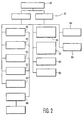
- Figure 3 illustrates a preferred methodology for programming the main data set 20 in a flowchart diagram 70.
- the main data set 20 preferably includes information from a technical manual, and typically includes a plurality of diagrams and textual informations.
- the main data set 20 preferably is programmed to include the diagrams in a stack file. To do so, a diagram name is entered at step 72. Thereafter, the diagram grid size or dimensions are entered at step 74. The diagram itself is then placed in the stack at step 76. In this step, the diagram can be converted from paper, such as by a conventional scanning method. Alternatively, the diagram can be entered directly or transferred from a binary form, or otherwise.
- step 78 This portion of the programming may be carried out in a Windows environment, using a graphics engine, such as AccuSoft IFL. Alternatively, programming could be accomplished in a DOS, or other, environment.
- the programmer identifies the components in order to program the various components from the diagram into the appropriate database. Identifying the components typically includes assigning a name, number or other identifier to each respective component. Thereafter, the component is located on a diagram displayed on the screen at step 80. Following step 80, the programmer arranges the preferred default view of the component in step 82, which step includes a preferred zoom factor and position on the screen. In step 84, the database records the location of the default view for the component on the diagram, given the known grid size and zoom factor. Steps 78-84 are repeated for other selected, and preferably all, components on a particular diagram, as indicated in step 86. The entire procedure is repeated for each diagram, as indicated by step 88.
- the ability to cross-reference between diagrams is provided within the main data set 20.
- the diagrams preferably are placed within a data stack in an arrangement that facilitates cross-referencing.
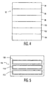
- Figure 4 schematically illustrates a stack of diagrams 92.
- Diagrams can be arranged with a stack in any order.
- the pointer that establishes any required relationship between diagrams is accomplished from pointer fields within the databases used to establish user lists and control access to graphics stack files.
- each component's unique identifier is established either manually or automatically depending on the original file's format.
- components preferably are identified manually.
- the component information imbedded therein typically is in a form suitable for automatic identification.
- the main data set 20 includes information that enables the program to move from one diagram to the next, displaying the same component, as directed by the menu or other choices of a user.
- the stack of diagrams 92 is exemplary of this feature.
- diagram 94 of a circuit schematic corresponds to diagram 96 of a circuit board diagram.
- Diagrams 98 and 100 are two parts of the same diagram and, therefore, are preferably placed adjacent each other in stack 92.
- diagrams 98 and 100 correspond to diagrams 102 and 104 which comprise circuit board diagrams.
- Recording the information about individual components creates a custom grid system of locations for the various components, even when the original diagram does not include such a grid system. Moreover, the recorded information cross-references schematic diagrams to circuit diagrams. Component identity and component coordinates on the screen, and within individual diagrams, are also cross-referenced. Further, the programmer-selected default display of that component (including zoom factor, for example) is also stored associated to that component. Accordingly, a user of the system is enabled, such as by simple menu choices, to locate particular portions of a diagram or components therein, or both, and to quickly gain further information regarding such portions and/or components, such as by cross-referencing to written descriptions or other diagrams. A user of a system of the invention does not generally execute the programming of Figure 3. Rather, such programming steps are accomplished during a programming phase for creating the system. The user of the system is then simply presented with the completed service manual in a suitable computer format, that results from the programming.
- a significant advantage of the invention is the ability for a user, such as a service technician, to access the information in the service manual according to nature of the actual problem. For example, if a customer's television produces no sound, the system and method hereof enables the service technician to access the appropriate electronic manual and, by making one or more selections, to quickly determine whether guidelines are available for effecting an appropriate repair.
- fault information preferably is placed within a fault database 106 as illustrated in Figure 5.
- the fault database includes a problem identifier portion 108, a memo field 110 and an additional view field 112.
- the problem identifier portion 108 enables the user to choose among several known problems associated with the particular device. For each problem provided in the problem identifier portion 108, a separate memo field 60 may be provided. Each memo field 60 may identify and describe the problem in such manner that the service technician can compare the information therein with the defects such as reported by a customer, or identified by some preliminary performance tests conducted by the technician.
- the additional view field 112 provides further information, such as diagrams, clips or other tutorial material to assist the technician.
- the field 112 can provide illustration of how to add additional circuit components or how to change circuit boards, which procedures generally are not illustrated in the original drawings of the service manual.
- providing a fault database 106 enables a user to find solutions of a problem the user making one or more choices, e.g., menu selections.
- Fault databases may be incorporated into the main data set 20, or may be provided separately.
- a separate database 106 is preferred, because such structure enables manufacturers to augment or supplement the main data set 20 upon becoming aware of each new problem with a product, particularly after the product has been on the market.
- the fault database 106 preferably is updated periodically by providing update information to the user on floppy disks or via online transmission, or otherwise.
- the user ultimately controls inputting that information into the fault database.
- diagrams can be updated with or without replacing the existing diagrams in the main stack 22 or the main data set 20. It is possible to augment the main data set 20 and therefore, the service manual, with optional accessory and/or supporting programs. Such programs preferably are stored in the database of Figure 1.
- a price information program that may include pricing information regarding various components, as well as current commercial availability and potential substitutes.
- the invention allows to combine various forms of technical information in one easily-manipulated source. Having such variety of technical information combined and available in an inter-related and cross-referenced structure, provides great advantages over prior systems.
Landscapes
- Engineering & Computer Science (AREA)
- Theoretical Computer Science (AREA)
- Physics & Mathematics (AREA)
- General Engineering & Computer Science (AREA)
- General Physics & Mathematics (AREA)
- Audiology, Speech & Language Pathology (AREA)
- Computational Linguistics (AREA)
- General Health & Medical Sciences (AREA)
- Health & Medical Sciences (AREA)
- Artificial Intelligence (AREA)
- Data Mining & Analysis (AREA)
- Databases & Information Systems (AREA)
- Management, Administration, Business Operations System, And Electronic Commerce (AREA)
- User Interface Of Digital Computer (AREA)
- Information Retrieval, Db Structures And Fs Structures Therefor (AREA)
Claims (6)
- Système pour accéder à des données techniques (94, 96) et pour utiliser celles-ci, comprenant :caractérisé en ce queun jeu de données (20) contenant les données techniques, dont:des informations d'identification identifiant chaque élément d'une pluralité d'éléments;des informations descriptives décrivant chaque élément de ladite pluralité d'éléments;une pluralité de schémas, chacun contenant des éléments sélectionnés parmi ladite pluralité d'éléments, chaque dit élément sur chaque schéma ayant une localisation spécifiée sur le schéma, etdes informations de liaison reliant lesdites informations d'identification, lesdites informations descriptives et ladite localisation sur le schéma pour chaque élément desdits éléments;un module de commande destiné à commander l'accès audit jeu de données, ledit jeu de données et ledit module de commande étant stockés dans une mémoire d'ordinateur,
lesdites données techniques (94, 96) sont des données techniques liées au hardware, comme des données de dépannage de hardware, lesdits éléments sont des éléments de hardware, et lesdits schémas sont des schémas de hardware, et en ce que le système comprend en outre :une base de données principale (23) comportant lesdites informations descriptives;une base de données de localisation (24) comportant ladite localisation sur le schéma;une pile principale (22) comportant ladite pluralité de schémas, etun dispositif d'interface destiné à assurer l'interface avec ledit module de commande de manière à localiser un élément sélectionné desdits éléments de hardware dans ledit jeu de données sur un desdits schémas de hardware, ou par le biais d'une desdites informations d'identification, ou par le biais desdites infirmations descriptives, et en ce que ledit module de commande accède automatiquement auxdites autres informations d'identification ou descriptives, ainsi qu'à tout schéma parmi lesdits schémas de hardware contenant ledit élément de hardware sélectionné par le biais desdites informations de liaison, en réaction audit dispositif d'interface; etet destiné à interagir automatiquement avec une base de données externe (32) afin d'extraire des informations supplémentaires pour l'élément sélectionné et localisé parmi lesdits éléments de hardware. - Système suivant la revendication 1, dans lequel certains desdits éléments sont répétés sur plus d'un desdits schémas, et dans lequel lesdites informations de liaison relient en outre tout schéma parmi lesdits schémas qui contiennent lesdits éléments répétés, et dans lequel ledit module de commande accède automatiquement à ladite localisation sur le schéma pour chaque dit élément sur lesdits schémas liés en réaction audit dispositif d'interface.
- Système suivant la revendication 2, dans lequel les données techniques décrivent des produits électroniques, les éléments sont des composants électroniques desdits produits, et lesdits schémas comprennent des schémas de principe et des schémas de cartes de circuit imprimé illustrant un agencement desdits composants, et dans lequel lesdites informations de liaison relient des schémas de principe avec des schémas de cartes de circuit imprimé contenant les mêmes composants.
- Système suivant la revendication 1, dans lequel lesdites données techniques décrivent des produits électroniques, les éléments sont des composants électroniques desdits produits, et ledit jeu de données comprend en outre des informations d'instructions décrivant la manière dont on peut remédier à des pannes connues pour un produit présélectionné et des composants pertinents du produit, et dans lequel lesdites informations de liaison relient en outre lesdites informations d'instructions auxdites localisations sur le schéma pour ledit composant pertinente, ou auxdites informations descriptives et d'identification pour ledit composant pertinent.
- Procédé d'agencement d'une mémoire d'ordinateur devant contenir des données techniques (94, 96) dont des schémas présentant une pluralité d'éléments sur chaque schéma, comprenant les étapes suivantes :(A) identifier chacun des éléments sur chaque schéma, et attribuer un identificateur unique à chaque élément;(B) décrire chacun des éléments identifiés au cours de l'étape (A) avec des informations descriptives, et(C) localiser chaque élément sur les schémas, et déterminer une localisation sur le schéma pour chaque élément sur chaque schéma,
caractérisé en ce que
lesdites données techniques sont des données techniques liées au hardware, comme des données de dépannage de hardware, lesdits éléments sont des éléments de hardware, et lesdits schémas sont des schémas de hardware, et en ce que
les informations descriptives sont comprises à l'intérieur d'une base de données principale; la localisation sur le schéma est comprise à l'intérieur d'une base de données de localisation (24), la pluralité de schémas est comprise à l'intérieur d'une pile principale (22),
et le procédé comprend en outre :(D) la liaison des localisations de hardware sur le schéma provenant de l'étape (C) avec les identificateurs provenant de l'étape (A) et les informations descriptives provenant de l'étape (B) pour chaque élément de hardware, attendu que les données techniques appartenant à chaque élément de hardware sont accessibles par l'un des identificateurs, ou par les informations descriptives, ou par la localisation sur le schéma de hardware, et dans lequel l'accès aux deux autres est disponible automatiquement. - Procédé suivant la revendication 5, dans lequel les données techniques décrivent un produit électronique, et dans lequel les éléments sont des composants électroniques du produit, et le procédé comprend en outre la détermination d'un état concernant le produit, la détermination d'une procédure pour traiter l'état comprenant l'identification des éléments qui sont impliqués dans la procédure, la description de la procédure, et la liaison de la description de procédure avec les localisations sur le schéma pour les éléments impliqués dans la procédure.
Applications Claiming Priority (3)
| Application Number | Priority Date | Filing Date | Title |
|---|---|---|---|
| US1721796P | 1996-05-09 | 1996-05-09 | |
| US17217P | 1996-05-09 | ||
| PCT/IB1997/000436 WO1997042575A2 (fr) | 1996-05-09 | 1997-04-24 | Systeme et procede de gestion d'informations techniques |
Publications (2)
| Publication Number | Publication Date |
|---|---|
| EP0842477A2 EP0842477A2 (fr) | 1998-05-20 |
| EP0842477B1 true EP0842477B1 (fr) | 2005-06-08 |
Family
ID=21781388
Family Applications (1)
| Application Number | Title | Priority Date | Filing Date |
|---|---|---|---|
| EP97915654A Expired - Lifetime EP0842477B1 (fr) | 1996-05-09 | 1997-04-24 | Systeme et procede de gestion d'informations techniques |
Country Status (5)
| Country | Link |
|---|---|
| US (1) | US5884315A (fr) |
| EP (1) | EP0842477B1 (fr) |
| JP (1) | JPH11509662A (fr) |
| DE (1) | DE69733459T2 (fr) |
| WO (1) | WO1997042575A2 (fr) |
Families Citing this family (20)
| Publication number | Priority date | Publication date | Assignee | Title |
|---|---|---|---|---|
| US6167401A (en) * | 1998-02-09 | 2000-12-26 | Ciena Corporation | Manufacturing control network having a relational database |
| EP1145149B1 (fr) * | 1998-11-13 | 2005-04-06 | Cellomics, Inc. | Procedes et systeme de collection et de stockage efficaces de donnees experimentales |
| JP3211798B2 (ja) * | 1999-01-21 | 2001-09-25 | 村田機械株式会社 | 生産機械 |
| US6377956B1 (en) * | 1999-02-22 | 2002-04-23 | Siemens Corporate Research, Inc. | Automatically configuring product manual by binding document objects in logical structure to proper versions of component documents in a document database |
| US6539399B1 (en) * | 1999-04-29 | 2003-03-25 | Amada Company, Limited | Stand alone data management system for facilitating sheet metal part production |
| JP3212983B1 (ja) * | 2000-10-31 | 2001-09-25 | 株式会社シイエム・シイ | 部品説明書の作成支援方法、部品説明書の作成支援システム、及びコンピュータ読取可能な記録媒体 |
| US6572556B2 (en) * | 2000-12-29 | 2003-06-03 | Ge Medical Systems Information Technologies | Distributed multi-user catalog-based system for real time data access during cardiology procedures |
| US7039653B2 (en) | 2001-10-23 | 2006-05-02 | General Electric Company | Computer-based method and system for guiding a purchaser to select an appliance and a venting arrangement suitable for the appliance |
| EP1406182A1 (fr) * | 2002-10-02 | 2004-04-07 | WirTek ApS | Méthode et système d'affichage d'information pour pour fournir de maniere automatique des renseignements techniques d'un terminal informatisé |
| JP4032306B2 (ja) * | 2003-04-01 | 2008-01-16 | 株式会社日立製作所 | 設計作業支援装置 |
| CN1826616A (zh) * | 2003-05-20 | 2006-08-30 | 日本胜利株式会社 | 电子化服务指南显示程序、记录了程序的记录介质、电子化服务指南显示控制方法、电子化服务指南显示控制装置、程序传送方法、程序传送装置、程序接收方法、及程序接收装置 |
| EP1626351A4 (fr) * | 2003-05-20 | 2012-08-08 | Jvc Kenwood Corp | Dispositif de controle d'affichage de manuel de maintenance electronique |
| US7725353B2 (en) * | 2003-05-20 | 2010-05-25 | Victor Company Of Japan, Ltd. | Electronic service manual display control device |
| US7499601B2 (en) * | 2003-05-20 | 2009-03-03 | Victor Company Of Japan, Ltd. | Electronic service manual display control device |
| US20060080606A1 (en) * | 2004-10-13 | 2006-04-13 | Glenn Lortscher | System and method for model-specific web help |
| WO2010132207A2 (fr) * | 2009-05-10 | 2010-11-18 | John Michael Bailey | Système, procédé et produit programme d'ordinateur pour collecter et gérer une vérification d'alliage |
| US8600978B2 (en) * | 2009-12-17 | 2013-12-03 | Verizon Patent And Licensing Inc. | Diverse route adjustment tool |
| TW201227263A (en) * | 2010-12-30 | 2012-07-01 | Hon Hai Prec Ind Co Ltd | System and method of setting initialization values for a oscillograph |
| DE112012007259T5 (de) | 2012-12-26 | 2015-09-24 | Mitsubishi Electric Corporation | Elektronik-Handbuch-Durchblätterapparatur und -system |
| EP3149584A4 (fr) * | 2014-05-27 | 2017-10-04 | Bipon AB | Système et procédé de gestion automatisée de composants techniques produits en série |
Family Cites Families (12)
| Publication number | Priority date | Publication date | Assignee | Title |
|---|---|---|---|---|
| US5497489A (en) * | 1987-05-05 | 1996-03-05 | Menne; David M. | Data storage and retrieval systems having labelling for data |
| US5119483A (en) * | 1988-07-20 | 1992-06-02 | Digital Equipment Corporation | Application of state silos for recovery from memory management exceptions |
| US5367671A (en) * | 1990-09-25 | 1994-11-22 | International Business Machines Corp. | System for accessing extended object attribute (EA) data through file name or EA handle linkages in path tables |
| JPH04152441A (ja) * | 1990-10-17 | 1992-05-26 | Fujitsu Ltd | データ・ベース処理方式 |
| US5303367A (en) * | 1990-12-04 | 1994-04-12 | Applied Technical Systems, Inc. | Computer driven systems and methods for managing data which use two generic data elements and a single ordered file |
| US5454101A (en) * | 1992-09-15 | 1995-09-26 | Universal Firmware Industries, Ltd. | Data storage system with set lists which contain elements associated with parents for defining a logical hierarchy and general record pointers identifying specific data sets |
| US5566333A (en) * | 1992-11-05 | 1996-10-15 | Trace Technologies, Inc. | Relational database information management system for facilitating normalization of a relational database |
| US5649192A (en) * | 1993-01-15 | 1997-07-15 | General Electric Company | Self-organized information storage system |
| US5414626A (en) * | 1993-05-19 | 1995-05-09 | Envirotest Systems Corp. | Apparatus and method for capturing, storing, retrieving, and displaying the identification and location of motor vehicle emission control systems |
| CA2185439C (fr) * | 1994-03-28 | 2000-08-22 | Paul Anthony Putland | Installation et procede permettant de stocker des donnees de diagramme |
| EP0679995B1 (fr) * | 1994-04-26 | 2000-10-04 | Sun Microsystems, Inc. | Méthode et appareil pour codage de données devant être auto-descriptives |
| US5682468A (en) * | 1995-01-23 | 1997-10-28 | Intergraph Corporation | OLE for design and modeling |
-
1996
- 1996-12-26 US US08/773,119 patent/US5884315A/en not_active Expired - Fee Related
-
1997
- 1997-04-24 JP JP9539677A patent/JPH11509662A/ja not_active Abandoned
- 1997-04-24 WO PCT/IB1997/000436 patent/WO1997042575A2/fr not_active Ceased
- 1997-04-24 EP EP97915654A patent/EP0842477B1/fr not_active Expired - Lifetime
- 1997-04-24 DE DE69733459T patent/DE69733459T2/de not_active Expired - Fee Related
Also Published As
| Publication number | Publication date |
|---|---|
| EP0842477A2 (fr) | 1998-05-20 |
| DE69733459D1 (de) | 2005-07-14 |
| DE69733459T2 (de) | 2006-03-23 |
| WO1997042575A2 (fr) | 1997-11-13 |
| WO1997042575A3 (fr) | 1998-01-08 |
| JPH11509662A (ja) | 1999-08-24 |
| US5884315A (en) | 1999-03-16 |
Similar Documents
| Publication | Publication Date | Title |
|---|---|---|
| US5884315A (en) | System and method for handling technical hardware related information | |
| US7356762B2 (en) | Method for the automatic generation of an interactive electronic equipment documentation package | |
| US6292806B1 (en) | Computer aided maintenance and repair information system for equipment subject to regulatory compliance | |
| US5778381A (en) | Computer aided maintenance and repair information system for equipment subject to regulatory compliance | |
| US6535890B2 (en) | Computer aided maintenance and repair information system for equipment subject to regulatory compliance | |
| US6795094B1 (en) | Method and apparatus for processing an image, and storage | |
| US6289254B1 (en) | Parts selection apparatus and parts selection system with CAD function | |
| US5465358A (en) | System for enhancing user efficiency in initiating sequence of data processing system user inputs using calculated probability of user executing selected sequences of user inputs | |
| US5774887A (en) | Customer service electronic form generating system | |
| US6542897B2 (en) | Customer support system using internet | |
| US5047977A (en) | Methods of generating and retrieving error and task message records within a multitasking computer system | |
| US20010047373A1 (en) | Publication file conversion and display | |
| US20030131290A1 (en) | Software system and methods for testing transactional servers | |
| US20040123284A1 (en) | System and method for dynamically creating a customized multi-product software installation plan | |
| JPH08241336A (ja) | 検索装置及び検索方法 | |
| US5592603A (en) | Method of and apparatus for customizing user interface | |
| JPH11312178A (ja) | コンピュータと携帯端末間のデータ連携システム及びそのデータ連携方法 | |
| EP1486899A1 (fr) | Système pour la création d'un catalogue des pièces et logiciel correspondant | |
| US5666542A (en) | Multimedia information add-on system | |
| CN1892657B (zh) | 信息处理设备及信息处理方法 | |
| US6717597B2 (en) | Contextual and dynamic command navigator for CAD and related systems | |
| US6300949B1 (en) | Information processor | |
| US5727205A (en) | File installation system for displaying bitmaps during file installation | |
| US5946691A (en) | Method of presenting, storing, and updating a filing identifier for a data record | |
| US7613729B2 (en) | Electronic service manual display program and apparatus associated therewith |
Legal Events
| Date | Code | Title | Description |
|---|---|---|---|
| PUAI | Public reference made under article 153(3) epc to a published international application that has entered the european phase |
Free format text: ORIGINAL CODE: 0009012 |
|
| AK | Designated contracting states |
Kind code of ref document: A2 Designated state(s): DE FR GB |
|
| RAP3 | Party data changed (applicant data changed or rights of an application transferred) |
Owner name: KONINKLIJKE PHILIPS ELECTRONICS N.V. |
|
| 17P | Request for examination filed |
Effective date: 19980708 |
|
| 17Q | First examination report despatched |
Effective date: 20020725 |
|
| GRAP | Despatch of communication of intention to grant a patent |
Free format text: ORIGINAL CODE: EPIDOSNIGR1 |
|
| GRAS | Grant fee paid |
Free format text: ORIGINAL CODE: EPIDOSNIGR3 |
|
| GRAA | (expected) grant |
Free format text: ORIGINAL CODE: 0009210 |
|
| AK | Designated contracting states |
Kind code of ref document: B1 Designated state(s): DE FR GB |
|
| REG | Reference to a national code |
Ref country code: GB Ref legal event code: FG4D |
|
| REF | Corresponds to: |
Ref document number: 69733459 Country of ref document: DE Date of ref document: 20050714 Kind code of ref document: P |
|
| ET | Fr: translation filed | ||
| PLBE | No opposition filed within time limit |
Free format text: ORIGINAL CODE: 0009261 |
|
| STAA | Information on the status of an ep patent application or granted ep patent |
Free format text: STATUS: NO OPPOSITION FILED WITHIN TIME LIMIT |
|
| PG25 | Lapsed in a contracting state [announced via postgrant information from national office to epo] |
Ref country code: GB Free format text: LAPSE BECAUSE OF NON-PAYMENT OF DUE FEES Effective date: 20060424 |
|
| REG | Reference to a national code |
Ref country code: GB Ref legal event code: 746 Effective date: 20060331 |
|
| 26N | No opposition filed |
Effective date: 20060309 |
|
| PG25 | Lapsed in a contracting state [announced via postgrant information from national office to epo] |
Ref country code: DE Free format text: LAPSE BECAUSE OF NON-PAYMENT OF DUE FEES Effective date: 20061101 |
|
| GBPC | Gb: european patent ceased through non-payment of renewal fee |
Effective date: 20060424 |
|
| REG | Reference to a national code |
Ref country code: FR Ref legal event code: ST Effective date: 20061230 |
|
| PG25 | Lapsed in a contracting state [announced via postgrant information from national office to epo] |
Ref country code: FR Free format text: LAPSE BECAUSE OF NON-PAYMENT OF DUE FEES Effective date: 20060502 |