EP0842678A1 - Abstützungsplatte für Schuhe auf Skis - Google Patents
Abstützungsplatte für Schuhe auf Skis Download PDFInfo
- Publication number
- EP0842678A1 EP0842678A1 EP97410122A EP97410122A EP0842678A1 EP 0842678 A1 EP0842678 A1 EP 0842678A1 EP 97410122 A EP97410122 A EP 97410122A EP 97410122 A EP97410122 A EP 97410122A EP 0842678 A1 EP0842678 A1 EP 0842678A1
- Authority
- EP
- European Patent Office
- Prior art keywords
- friction
- support
- support device
- movable
- movable support
- Prior art date
- Legal status (The legal status is an assumption and is not a legal conclusion. Google has not performed a legal analysis and makes no representation as to the accuracy of the status listed.)
- Granted
Links
Images







Classifications
-
- A—HUMAN NECESSITIES
- A63—SPORTS; GAMES; AMUSEMENTS
- A63C—SKATES; SKIS; ROLLER SKATES; DESIGN OR LAYOUT OF COURTS, RINKS OR THE LIKE
- A63C9/00—Ski bindings
- A63C9/001—Anti-friction devices
Definitions
- the present invention relates to a support device for a ski boot on a ski and more particularly an improvement intended for mobile support at least transversely to the axis longitudinal of the ski.
- the shoe of a skier is retained on the ski so triggered by its front end thanks to a front fixing called commonly “stop”, and by its rear end, and in particular its heel, thanks to a rear attachment commonly known as a “heel piece”.
- the release of the ski boot, endangering the skier's leg or joints is done by release either from the front or the heel of the shoe, or from both to the time.
- the front stop comprises, for example, a jaw pivoting at least laterally around a vertical axis
- the heel piece usually includes an upwardly swiveling jaw around a transverse axis, the jaw of the stopper and that of the each heel being acted upon by a trigger spring whose compression is adjustable to provide the skier with an effort value for the release of his adapted shoe.
- the present invention therefore seeks to solve the drawbacks mentioned previously by proposing that an anti-friction element be provided between the movable element and its support.
- the device for supporting a ski boot on a ski comprises a movable support element for the shoe which is mobile at least in transverse displacement on a support and is characterized in that the movable support element rests on the support downward and at least forward and / or backward through at least one anti-friction element.
- the upward retention of the movable support element is done by through an anti-friction element.
- the anti-friction element is made of a material with a low coefficient of friction, such as example, a material with a lower coefficient of friction than the one in which the support and / or the movable support element is produced.
- a material with a low coefficient of friction such as example, a material with a lower coefficient of friction than the one in which the support and / or the movable support element is produced.
- it can be made of polytetrafluoroethylene or polyethylene of high density, while the support is made of polypropylene or polyamide and the movable support element (10) is made of plastic material such as acetal or other resin as in metallic material.
- the anti-friction element includes a horizontal bottom anti-friction pad and at least a front anti-friction plate. In a preferred mode, the element also includes a rear anti-friction pad.
- the front anti-friction plate and / or rear is integral and integral with the anti-friction plate lower, while in another embodiment the plate front and / or rear antifriction is independent of the pad lower antifriction.
- the anti-friction element comprises at least one plate horizontal lower friction placed between the underside of the movable support element and the upper surface of the groove displacement of said movable support element, said anti-friction element further comprising a front anti-friction plate and a plate rear anti-friction, the front anti-friction plate being disposed between the back side of the front groove and the front side of the front edge of the movable support element, while the rear anti-friction plate is disposed between the front face of the rear groove and the rear face of said mobile support element.
- the movable support element moves transversely in a curved sliding groove made in the support, while that the movable support element is a curved profile with the same curvature as said groove.
- the radius of curvature is between 150 and 300 millimeters, as per example 230 millimeters.
- Figure 1 is a side view of a ski with its front bindings and rear retaining shoe and the device of the invention.
- Figure 2 is a top view of Figure 1 without the shoe.
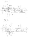
- Figures 3a and 3b are views similar to Figure 2 showing respectively the shift to the right and to the left of the movable element of the device.
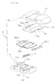
- Figure 4 is an exploded perspective view of the device the invention according to its first embodiment.
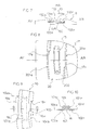
- Figure 5 is an exterior view from above, the movable element being represented in thin mixed lines in two displacement positions lateral.
- FIGS. 6a, 6b, 6c are respectively sections according to A-A, B-B and C-C in Figure 5 with partial magnifications.
- Figure 7 is an external side view of the device without the movable element, nor the spring, that is to say representing the support with its anti-friction element.
- Figure 8 is a top view of the base with the element anti-friction, the upper element of the support as well as the mobile element having been withdrawn.
- Figure 9 is an exterior top view of the movable member.
- FIG. 10 is a sectional view along D-D of FIG. 9.
- FIGS 11 and 11a illustrate an alternative embodiment in similar views to Figures 4 and 6a of the first embodiment.
- Figures 12 and 12a illustrate a second alternative embodiment in views similar to FIGS. 4 and 6a of the first mode of production.
- Figures 13 and 13a illustrate a third alternative embodiment in views similar to FIGS. 4 and 6a of the first mode of production.
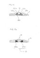
- Figure 14 is a sectional view of another embodiment.
- FIG. 15 is a view similar to FIG. 4, while Figure 15a is a cross section.
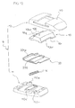
- Figure 16 is a view similar to Figure 4 illustrating a variant.
- the boot (1) of the skier is retained on the ski (2) of triggered by its front end (3) thanks to a fixing of front safety (4) commonly called “stop” and by its end rear and in particular its heel (5) thanks to a rear safety fastening (6) called “heel piece”.
- the support device (8) consists of a support (9) and a movable support element (10), said support (9) being fixed skiing, while the movable support element (10) is movable relative said support (9).
- the movable support element (10) is in projecting from its support and that it is on this support element (10) that the shoe is in support.
- the upper surface (100) of the movable support element (10) is arranged projecting relative to the upper surface (90) of the support (9).
- the width (L9) of the support (9) is substantially equal to the length (L2) of the ski (2) and is constituted by a base (11) on which is fixed an upper support element (12) or cover, the base and the element support upper being, for example, of large plastic resistance such as, for example, acetal type resin, polypropylene or polyamide.
- the base (11) is, for example, fixed to the ski by gluing, by screws or by its connection with the front binding (4) like, for example, with its base plate (40).
- the movable support element (10) which can be, for example, metallic or any other material such as, in particular resin acetal, extends advantageously and in any case as on the mode illustrated, over the entire width of the support and is movable by relation to the latter at least transversely to the right (DR) or to left (GA) with respect to the longitudinal plane (XX ') of general symmetry.
- the displacement of the element mobile support is done transversely along a transverse trajectory (T) circular of radius (R) centered at a point (O) located in the plane of general symmetry (XX '), the radius (R) being, for example, between 150 and 300 mm and equal, for example, to 230 mm.
- the movable support element (10) is a shape profile slightly curved and moves transversely to slide in a sliding groove (13) of corresponding shape produced in the support (9). Note that in the rest position the movable support element is centered and held in this position thanks to an elastic system while it can slide by sliding in the groove towards the right (DR) or left (GA) against the action of said elastic system constituted, for example, by a compression spring (14).
- the sliding groove (13) extends over the entire width of the support, has the general shape of an inverted T to open up (HA) and laterally to the left (GA) and to the right (DR) and includes a central part (130) open upwards (HA) and two grooves, a front groove (131a) and a rear groove (131r), to constitute two vertical retaining projections towards the top of the movable support element (10), namely, a front projection (132a) and a rear projection (132r) (see in particular figure 7). Note that the groove is curved.
- the movable support element (10) consists of a transverse profile whose cross section corresponds to the cross section of the groove (13) corresponding.
- the movable support element (1 0) extends advantageously, for example, over the entire width of the support and at the shaped like an inverted T. It is constituted by a transverse body (101) whose the lower part is extended at the front by a lower front edge (102a) and at the rear by a rear lower edge (102r) (see in particular figure 10). Note that said lower front edges and rear (102a, 102r) are intended to be engaged in the front grooves and rear (131a, 131r) corresponding to the support.
- a spring (14) allows keep the movable support element in a centered position, lateral displacements of said movable support element being made against the action of this spring (14).
- the spring is, by its half lower, housed in a lower spring housing (15) made in the support and more particularly in the upper surface (133) of the groove (13), said upper surface (133) of the groove (13) being constituted by said base (11) in the proposed embodiment.
- the spring (14) is, by its upper rise, housed in a upper spring housing (16) made in the lower surface (103) of the movable support element (10).
- the upper spring housing (16) is equal in length to the length of the lower spring housing (15) and equal to the length of the spring which was slightly compressed during of its mounting, to be prestressed when the movable support element is in centered position.
- the latter compresses the spring either on one side or on the other, to ensure the recall of said movable member in its centered position.
- stop means for limiting the lateral movement of the movable support element (10) constituted by a stop system.
- a stop system it is provided on the support, and more particularly on the base, two stops, namely, a straight stop (17a) limiting the movement to the right of the movable support element (10) and a left stop (17r) limiting the movement to the left of the movable support element (10), the two stops (17a, 17r) cooperating with a corresponding stop (18a, 18b) produced on the movable support element (10).
- the two stops (18a, 18b) are, for example, formed by a clearance (19a, 19b) produced in the edges respectively (102a, 102b).
- This element is intended to favor and control the lateral displacements of the movable support element (10) relative to the support.
- the element of sliding is made of low friction material such as, for example, polytetrafluoroethylene (PTFE) or high density polyethylene, or even a material such as polytetrafluoroethylene loaded with bronze beads, or any other material appropriate.
- the anti-friction element is in a weaker material coefficient of friction as the material from which the support (9) is made and more particularly the material of the sliding groove (13).
- the anti-friction element (20) is also and advantageously made in a material with a lower coefficient of friction than the material of which made the movable support element (10).
- An anti-friction element (20) comprising at less a horizontal lower anti-friction plate (200) arranged between the underside (103) of the movable support element (10) and the upper surface (133) of the groove (13) for moving said element mobile support. Furthermore, and according to an additional characteristic, the anti-friction element (20) further comprises an anti-friction plate front (201a) and a rear anti-friction plate (201r).
- the brochure frontal antifriction (201a) being disposed between the rear face (133a) of the front groove (131a) and the front face (104a) of the front edge (102a) of the movable support element (10), while the rear anti-friction plate (201r) is disposed between the front face (133r) of the rear groove (131r) and the rear face (104r) of said movable support element (10).
- the brochure frontal antifriction (201a) is the antifriction element placed between the movable support element (10) and the support (9) through which leans forward (AV) the movable support element (10), the element front anti-friction (201a) serving as a forward stop for the element support mobile (10), while the rear anti-friction plate (201r) is the anti-friction element arranged between the movable support element (10) and the support (9) through which backs (AR) the movable support element (10) and serves as a rearward stop for this latest.
- the two front anti-friction pads (201a) and rear (201r) are extensions of the plate lower antifriction (200) to form with it one and the same part which is fixed in the groove (13) for moving the element mobile support (10) and is made integral with the support (9) by any means such as welding, gluing or embedding.
- the anti-friction element (20) is retained in the groove by two projections side (110a, 110r) and a central projection (110r).
- each of the pads i.e., the front pad (201a) and the rear plate (201r) is engaged in a transverse groove corresponding (111a, 111r) produced in the base (11).
- frontal anti-friction pads (201a) and rear (201r) could be arranged between the front projections (132a) and rear (132r) and the lateral flanks respectively front (101a) and rear (101r) of the transverse body (101), as shown schematically in Figure 14.
- the width of the anti-friction element is substantially equal to the width of the sliding groove and the width of the movable support element.
- the anti-friction element is totally the shelter in the sliding groove and is thus protected from dirt or possible scratches, which improves, of course, the conditions of functioning of the product, but also its aging.
- front anti-friction elements (201a, 201r) are advantageously housed under the vertical retaining projections (132a, 132r) of the movable support element.
- Figures 15 and 15a illustrate an embodiment comprising an anti-friction element retaining the element upwards mobile support.
- a front anti-friction element (20a) and a rear anti-friction element (20r) constituted by a transverse profile in U shape each constituting the downward support (200a, 200r), the support front and rear (201a, 201r) making stop and the upper front support and rear (202a, 202r).
- Figure 16 is an alternative embodiment of the embodiment of the Figure 4 according to which the movable support element (2a) consists of a mobile front support element (20a) and a mobile support element rear (20r), the two mobile support elements being independent and not united.
- the support (9) itself constituted the movable support element. So and as it is illustrated in Figure 17, the base (11) is made directly of material antifriction with low coefficient of friction.
Landscapes
- Footwear And Its Accessory, Manufacturing Method And Apparatuses (AREA)
- Organic Low-Molecular-Weight Compounds And Preparation Thereof (AREA)
- Golf Clubs (AREA)
Applications Claiming Priority (2)
| Application Number | Priority Date | Filing Date | Title |
|---|---|---|---|
| FR9614339A FR2755868B1 (fr) | 1996-11-18 | 1996-11-18 | Dispositif d'appui d'une chaussure de ski sur un ski |
| FR9614339 | 1996-11-18 |
Publications (2)
| Publication Number | Publication Date |
|---|---|
| EP0842678A1 true EP0842678A1 (de) | 1998-05-20 |
| EP0842678B1 EP0842678B1 (de) | 2001-07-25 |
Family
ID=9497941
Family Applications (1)
| Application Number | Title | Priority Date | Filing Date |
|---|---|---|---|
| EP97410122A Expired - Lifetime EP0842678B1 (de) | 1996-11-18 | 1997-10-24 | Abstützungsplatte für Schuhe auf Skis |
Country Status (5)
| Country | Link |
|---|---|
| US (1) | US6290251B1 (de) |
| EP (1) | EP0842678B1 (de) |
| AT (1) | ATE203425T1 (de) |
| DE (1) | DE69705804T2 (de) |
| FR (1) | FR2755868B1 (de) |
Cited By (2)
| Publication number | Priority date | Publication date | Assignee | Title |
|---|---|---|---|---|
| FR2816850A1 (fr) * | 2000-11-22 | 2002-05-24 | Look Fixations Sa | Dispositif d'appui d'une chaussure sur un ski |
| EP2431079A3 (de) * | 2010-09-17 | 2013-05-22 | Tyrolia Technology GmbH | Sohlenauflageplatte und Skibindung mit einer Sohlenauflageplatte |
Families Citing this family (6)
| Publication number | Priority date | Publication date | Assignee | Title |
|---|---|---|---|---|
| FR2803533B1 (fr) | 2000-01-07 | 2002-04-05 | Look Fixations Sa | Dispositif d'appui pour l'avant d'une chaussure de ski sur un ski |
| ATE309034T1 (de) * | 2001-03-08 | 2005-11-15 | Scarpa Calzaturificio Spa | Vorrichtung zum skibergsteigen |
| FR2837716B1 (fr) | 2002-03-27 | 2004-05-14 | Rossignol Sa | Dispositif d'appui pour un element de fixation et planche de glisse sur neige ainsi equipee |
| US7874591B2 (en) * | 2005-11-12 | 2011-01-25 | Biostance Llc | Apparatus and method for canting a skier |
| CN101780321B (zh) * | 2009-12-30 | 2012-01-25 | 永春至善体育用品有限公司 | 一种高临场感的运动健身器材虚拟实景的制作方法以及基于该虚拟实景的互动系统和方法 |
| CN105929955B (zh) * | 2016-04-22 | 2019-07-26 | 北京圣威特科技有限公司 | 一种虚拟现实的运动模拟方法及装置 |
Citations (5)
| Publication number | Priority date | Publication date | Assignee | Title |
|---|---|---|---|---|
| CH477890A (fr) * | 1967-06-22 | 1969-09-15 | Reuge Sa | Fixation de ski de sécurité |
| FR2125782A5 (en) * | 1971-02-15 | 1972-09-29 | Ramillon Rene | Antifriction ski device - with eg ptfe coatings for relative motion of the ski shoe |
| FR2652508A1 (fr) | 1989-09-29 | 1991-04-05 | Salomon Sa | Dispositif d'appui, sur un ski, de la partie anterieure de la semelle d'une chaussure. |
| EP0447779A2 (de) * | 1990-03-17 | 1991-09-25 | Geze Sport International Gmbh | Lagervorrichtung zur seitwärts beweglichen vertikalen Abstützung eines Skischuhes auf einem Ski |
| EP0729771A1 (de) * | 1995-03-03 | 1996-09-04 | Salomon S.A. | Trägerplatte für Skibindung |
Family Cites Families (4)
| Publication number | Priority date | Publication date | Assignee | Title |
|---|---|---|---|---|
| FR2471795B1 (fr) * | 1979-12-21 | 1985-05-31 | Look Sa | Butee-avant de fixation de ski |
| USRE33388E (en) * | 1984-01-02 | 1990-10-16 | Marker Deutschland Gmbh | Toe piece for a safety ski-binding |
| FR2602687B1 (fr) * | 1986-08-05 | 1988-11-10 | Salomon Sa | Plaque antifriction libre a recentrage automatique pour fixation de securite |
| FR2609900B1 (fr) * | 1987-01-28 | 1989-05-05 | Salomon Sa | Plaque antifriction libre a coulisseau de recentrage automatique pour fixation de securite |
-
1996
- 1996-11-18 FR FR9614339A patent/FR2755868B1/fr not_active Expired - Fee Related
-
1997
- 1997-10-24 AT AT97410122T patent/ATE203425T1/de not_active IP Right Cessation
- 1997-10-24 DE DE69705804T patent/DE69705804T2/de not_active Expired - Lifetime
- 1997-10-24 EP EP97410122A patent/EP0842678B1/de not_active Expired - Lifetime
- 1997-11-17 US US08/971,611 patent/US6290251B1/en not_active Expired - Fee Related
Patent Citations (5)
| Publication number | Priority date | Publication date | Assignee | Title |
|---|---|---|---|---|
| CH477890A (fr) * | 1967-06-22 | 1969-09-15 | Reuge Sa | Fixation de ski de sécurité |
| FR2125782A5 (en) * | 1971-02-15 | 1972-09-29 | Ramillon Rene | Antifriction ski device - with eg ptfe coatings for relative motion of the ski shoe |
| FR2652508A1 (fr) | 1989-09-29 | 1991-04-05 | Salomon Sa | Dispositif d'appui, sur un ski, de la partie anterieure de la semelle d'une chaussure. |
| EP0447779A2 (de) * | 1990-03-17 | 1991-09-25 | Geze Sport International Gmbh | Lagervorrichtung zur seitwärts beweglichen vertikalen Abstützung eines Skischuhes auf einem Ski |
| EP0729771A1 (de) * | 1995-03-03 | 1996-09-04 | Salomon S.A. | Trägerplatte für Skibindung |
Cited By (3)
| Publication number | Priority date | Publication date | Assignee | Title |
|---|---|---|---|---|
| FR2816850A1 (fr) * | 2000-11-22 | 2002-05-24 | Look Fixations Sa | Dispositif d'appui d'une chaussure sur un ski |
| US6623026B2 (en) | 2000-11-22 | 2003-09-23 | Look Fixations S.A. | Support device for a ski boot |
| EP2431079A3 (de) * | 2010-09-17 | 2013-05-22 | Tyrolia Technology GmbH | Sohlenauflageplatte und Skibindung mit einer Sohlenauflageplatte |
Also Published As
| Publication number | Publication date |
|---|---|
| FR2755868A1 (fr) | 1998-05-22 |
| DE69705804D1 (de) | 2001-08-30 |
| EP0842678B1 (de) | 2001-07-25 |
| ATE203425T1 (de) | 2001-08-15 |
| DE69705804T2 (de) | 2002-04-04 |
| FR2755868B1 (fr) | 1999-01-08 |
| US6290251B1 (en) | 2001-09-18 |
Similar Documents
| Publication | Publication Date | Title |
|---|---|---|
| FR2719229A1 (fr) | Dispositif de fixation d'une chaussure à un ski de fond. | |
| EP0031740A1 (de) | Vorderbacke für Skibindung | |
| EP0422382B1 (de) | Einrichtung beim Langlaufski um Rückwärtsgleiten zu vermeiden | |
| EP0842678B1 (de) | Abstützungsplatte für Schuhe auf Skis | |
| EP0241360B1 (de) | Sicherheitsskibindung | |
| WO1991008808A1 (fr) | Fixation de securite de ski alpin | |
| FR2741543A1 (fr) | Fixations pour ski de fond | |
| FR2465498A1 (fr) | Element formant machoire avant ou arriere pour une fixation de ski | |
| FR2666020A1 (fr) | Fixation pour ski de fond. | |
| CH673400A5 (de) | ||
| EP1234604A1 (de) | Trägerplatte für ein Snowboard | |
| CH660976A5 (fr) | Fixation de securite pour ski. | |
| CH673776A5 (de) | ||
| EP0193686A1 (de) | Rückhaltevorrichtung für einen Schuh auf einem Ski | |
| EP1025768B1 (de) | Schischuh | |
| FR2502019A1 (fr) | Fixation de securite pour ski | |
| EP1656973A1 (de) | Vorrichtung zur Montage der Teile einer Sicherheitsbindung auf einem Ski | |
| EP0865806B1 (de) | Vorderbacken einer Sicherheitsskibindung | |
| EP1114656B1 (de) | Vorrichtung zum Stützen des Vorderteiles eines Schuhs auf einem Ski | |
| FR2598933A1 (fr) | Fixation de securite d'une chaussure sur un ski | |
| EP1138355B1 (de) | Vorrichtung zum Befestigen eines Schischuhes auf einem Schi | |
| EP0627947B1 (de) | Sohlenplatte verbunden mit einem vorderbacken einer sicherheitsskibindung | |
| CH619144A5 (de) | ||
| FR2511602A1 (fr) | Fixation de securite pour ski | |
| CH672433A5 (de) |
Legal Events
| Date | Code | Title | Description |
|---|---|---|---|
| PUAI | Public reference made under article 153(3) epc to a published international application that has entered the european phase |
Free format text: ORIGINAL CODE: 0009012 |
|
| AK | Designated contracting states |
Kind code of ref document: A1 Designated state(s): AT DE |
|
| AX | Request for extension of the european patent |
Free format text: AL;LT;LV;RO;SI |
|
| 17P | Request for examination filed |
Effective date: 19980910 |
|
| AKX | Designation fees paid |
Free format text: AT DE |
|
| RBV | Designated contracting states (corrected) |
Designated state(s): AT DE |
|
| 17Q | First examination report despatched |
Effective date: 20000711 |
|
| GRAG | Despatch of communication of intention to grant |
Free format text: ORIGINAL CODE: EPIDOS AGRA |
|
| GRAG | Despatch of communication of intention to grant |
Free format text: ORIGINAL CODE: EPIDOS AGRA |
|
| GRAH | Despatch of communication of intention to grant a patent |
Free format text: ORIGINAL CODE: EPIDOS IGRA |
|
| GRAH | Despatch of communication of intention to grant a patent |
Free format text: ORIGINAL CODE: EPIDOS IGRA |
|
| GRAA | (expected) grant |
Free format text: ORIGINAL CODE: 0009210 |
|
| AK | Designated contracting states |
Kind code of ref document: B1 Designated state(s): AT DE |
|
| REF | Corresponds to: |
Ref document number: 203425 Country of ref document: AT Date of ref document: 20010815 Kind code of ref document: T |
|
| REF | Corresponds to: |
Ref document number: 69705804 Country of ref document: DE Date of ref document: 20010830 |
|
| PLBE | No opposition filed within time limit |
Free format text: ORIGINAL CODE: 0009261 |
|
| STAA | Information on the status of an ep patent application or granted ep patent |
Free format text: STATUS: NO OPPOSITION FILED WITHIN TIME LIMIT |
|
| 26N | No opposition filed | ||
| PGFP | Annual fee paid to national office [announced via postgrant information from national office to epo] |
Ref country code: AT Payment date: 20081024 Year of fee payment: 12 |
|
| PG25 | Lapsed in a contracting state [announced via postgrant information from national office to epo] |
Ref country code: AT Free format text: LAPSE BECAUSE OF NON-PAYMENT OF DUE FEES Effective date: 20091024 |
|
| PGFP | Annual fee paid to national office [announced via postgrant information from national office to epo] |
Ref country code: DE Payment date: 20110902 Year of fee payment: 15 |
|
| PG25 | Lapsed in a contracting state [announced via postgrant information from national office to epo] |
Ref country code: DE Free format text: LAPSE BECAUSE OF NON-PAYMENT OF DUE FEES Effective date: 20130501 |
|
| REG | Reference to a national code |
Ref country code: DE Ref legal event code: R119 Ref document number: 69705804 Country of ref document: DE Effective date: 20130501 |