EP0842780A2 - Procédé de fabrication d'une cartouche d'encre utilisable avec un appareil d'enregistrement par jet d'encre - Google Patents
Procédé de fabrication d'une cartouche d'encre utilisable avec un appareil d'enregistrement par jet d'encre Download PDFInfo
- Publication number
- EP0842780A2 EP0842780A2 EP97309203A EP97309203A EP0842780A2 EP 0842780 A2 EP0842780 A2 EP 0842780A2 EP 97309203 A EP97309203 A EP 97309203A EP 97309203 A EP97309203 A EP 97309203A EP 0842780 A2 EP0842780 A2 EP 0842780A2
- Authority
- EP
- European Patent Office
- Prior art keywords
- ink
- container body
- cover
- foam chamber
- opening
- Prior art date
- Legal status (The legal status is an assumption and is not a legal conclusion. Google has not performed a legal analysis and makes no representation as to the accuracy of the status listed.)
- Granted
Links
Images




Classifications
-
- B—PERFORMING OPERATIONS; TRANSPORTING
- B41—PRINTING; LINING MACHINES; TYPEWRITERS; STAMPS
- B41J—TYPEWRITERS; SELECTIVE PRINTING MECHANISMS, i.e. MECHANISMS PRINTING OTHERWISE THAN FROM A FORME; CORRECTION OF TYPOGRAPHICAL ERRORS
- B41J2/00—Typewriters or selective printing mechanisms characterised by the printing or marking process for which they are designed
- B41J2/005—Typewriters or selective printing mechanisms characterised by the printing or marking process for which they are designed characterised by bringing liquid or particles selectively into contact with a printing material
- B41J2/01—Ink jet
- B41J2/17—Ink jet characterised by ink handling
- B41J2/175—Ink supply systems ; Circuit parts therefor
- B41J2/17503—Ink cartridges
- B41J2/17559—Cartridge manufacturing
-
- B—PERFORMING OPERATIONS; TRANSPORTING
- B41—PRINTING; LINING MACHINES; TYPEWRITERS; STAMPS
- B41J—TYPEWRITERS; SELECTIVE PRINTING MECHANISMS, i.e. MECHANISMS PRINTING OTHERWISE THAN FROM A FORME; CORRECTION OF TYPOGRAPHICAL ERRORS
- B41J2/00—Typewriters or selective printing mechanisms characterised by the printing or marking process for which they are designed
- B41J2/005—Typewriters or selective printing mechanisms characterised by the printing or marking process for which they are designed characterised by bringing liquid or particles selectively into contact with a printing material
- B41J2/01—Ink jet
- B41J2/17—Ink jet characterised by ink handling
- B41J2/175—Ink supply systems ; Circuit parts therefor
- B41J2/17503—Ink cartridges
- B41J2/17506—Refilling of the cartridge
-
- B—PERFORMING OPERATIONS; TRANSPORTING
- B41—PRINTING; LINING MACHINES; TYPEWRITERS; STAMPS
- B41J—TYPEWRITERS; SELECTIVE PRINTING MECHANISMS, i.e. MECHANISMS PRINTING OTHERWISE THAN FROM A FORME; CORRECTION OF TYPOGRAPHICAL ERRORS
- B41J2/00—Typewriters or selective printing mechanisms characterised by the printing or marking process for which they are designed
- B41J2/005—Typewriters or selective printing mechanisms characterised by the printing or marking process for which they are designed characterised by bringing liquid or particles selectively into contact with a printing material
- B41J2/01—Ink jet
- B41J2/17—Ink jet characterised by ink handling
- B41J2/175—Ink supply systems ; Circuit parts therefor
- B41J2/17503—Ink cartridges
- B41J2/17513—Inner structure
-
- B—PERFORMING OPERATIONS; TRANSPORTING
- B41—PRINTING; LINING MACHINES; TYPEWRITERS; STAMPS
- B41J—TYPEWRITERS; SELECTIVE PRINTING MECHANISMS, i.e. MECHANISMS PRINTING OTHERWISE THAN FROM A FORME; CORRECTION OF TYPOGRAPHICAL ERRORS
- B41J2/00—Typewriters or selective printing mechanisms characterised by the printing or marking process for which they are designed
- B41J2/005—Typewriters or selective printing mechanisms characterised by the printing or marking process for which they are designed characterised by bringing liquid or particles selectively into contact with a printing material
- B41J2/01—Ink jet
- B41J2/17—Ink jet characterised by ink handling
- B41J2/175—Ink supply systems ; Circuit parts therefor
- B41J2/17503—Ink cartridges
- B41J2/17533—Storage or packaging of ink cartridges
Definitions
- the invention relates to a method for manufacturing an ink cartridge for use in an ink jet recorder. More specifically, the present invention relates to a method of manufacturing an ink cartridge for use in an ink jet recorder that has a carriage equipped with an ink jet recording head and a replaceable ink cartridge.
- a conventional ink jet printer includes an ink container carried by a carriage equipped with an ink jet recording head.
- Ink droplets are produced by pressurizing the ink within a pressure generation chamber located within the ink container.
- the carriage is pivoted, shaken or caused to travel during printing, the movement can cause the ink to become frothy or foamy. This, in turn, may result in a change in head pressure or cause print failures.
- ink contains gas bubbles, the pressure at which the ink is under drops, thereby decreasing the ability to squirt ink droplets. For this reason, dissolved air must be eliminated from the ink.
- a container body with a porous material To manufacture a container body with a porous material, one can seal the container body with a cover; fill the container with degassed ink, and package the ink container such that the quality of the ink cartridge is maintained during distribution. To these ends, the manufacturing steps become complicated, thereby resulting in a decrease in productivity.
- an object of the present invention is to provide a manufacturing method that enables efficient and more simple manufacture of an ink cartridge for use in an ink jet recorder.
- a container body having a bottom wall and an opening can be positioned on a pallet such that the bottom wall faces upward.
- the container body can include a porous member, a foam chamber for accommodating the porous member therein, and an ink supply port, having an inlet formed in the bottom surface of the foam chamber and an outlet. Packing can be inserted into the ink supply port.
- the ink supply port outlet can be scaled and the container body reset on the pallet by turning the container body upside down such that the opening faces upward.
- a filter can then be affixed to the ink supply port inlet, and the porous member inserted into the foam chamber.
- a cover can then be bonded the opening of the container body, ink injected into the foam chamber, and the cover sealed.
- the invention accordingly comprises the several steps and the relation of one or more of such steps with respect to each of the others thereof, which will be exemplified in the method hereinafter disclosed, and the scope of the invention will be indicated in the claims.
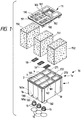
- FIG. 1 shows an ink cartridge 70 manufactured by a method in accordance with an embodiment of the present invention.
- Ink cartridge 70 includes a substantially rectangular container body 1, for preferably containing three colors of ink-cyan, magenta and yellow.
- Container body 1 is preferably formed from polymeric material, such as polypropylene, polyethylene, or polystyrene by injection molding to facilitate heat welding of other members to the container body.
- Container body 1 includes a bottom wall 1a, a front wall 1b and a back wall 1c extending upwardly from bottom wall 1a, and two side walls 1d extending upwardly from bottom wall 1a and positioned between front wall 1b and back wall 1c.
- the distance from front wall 1b to back wall 1c and between side walls 1d gradually increases as walls 1b, 1c, 1d extend from bottom wall 1a to an opening 1e of container body 1 such that the area of opening 1e is larger than the area of bottom wall 1a.
- Container body 1 is divided by partitions 2, 3 and 4 to define ink chambers 271, 272, 273 for storing ink and foam chambers 160, 161, 162 for receiving porous bodies.
- Each foam chamber 160, 161, 162 is designed to accommodate a respective porous body 150, 151, 152 made of a resilient material suitable for absorbing ink.
- Each ink chamber 271, 272, 273 is designed to contain liquid ink 67.
- the volumes of the porous bodies 150, 151, 152 are larger than the capacity of the respective foam chambers 160, 161, 162, so that, upon insertion into foam chamber 160, 161, 162, each of the porous bodies 150, 151, 152 is accommodated in a compressed condition.
- Ink is filled in foam chambers 10,161,162.
- each ink is introduced through an ink communication hole 300 to ink chambers 271, 272 and 273.
- ink contained in the ink chambers 271, 272, 273 is discharged out first. After the ink chambers 271, 272, 273 are depleted, then ink contained in the foam chambers 160, 161, 162 is consumed.
- Container body 1 also includes a plurality of ink feed parts 180, 181 and 182.
- Ink feed ports 180, 181, 182 are shaped to receive an ink supply needle of a recording head (not shown), and are formed in bottom walls 160a, 161a, 162a of respective foam chambers 160, 161, 162.
- cover 11 is preferably formed of polypropylene, polyethylene, or polystyrene to facilitate heat welding.
- FIGS. 4A and 4B a plan view of cover 11 is shown, wherein grooves 170, 171, 172 are formed in cover 11 so as to meander across the surface of cover 11. Grooves 170, 171, 172 are connected at one end to respective exhaust ports 190, 191, 192 and at the other end to the air communication ports 173, 174, 175 formed at the inner surface of cover 11.
- a seal 19 is secured to the surface of cover 11 so as to seal ink injection ports 100, 101, 102, exhaust ports 190, 191, 192, and grooves 170, 171, 172 from ambient air.
- Seal 19 includes a tongue 19a, which extends beyond cover 11, and is constructed to be easily grasped by a user. When tongue 19a is lifted, the seal between seal 19 and cover 11 is broken, and ambient air is provided to the interior of foam chambers 160, 161, 162, through exhaust ports 190, 191, 192, grooves 170, 171, 172, and air communication ports 173, 174, 175.
- a protuberance 12 extends upwardly from the bottom of each foam chamber 160, 161, 162, and sets to compress porous bodies 150, 151, 152 in cooperation with cover 11.
- a recess 13 is formed in the upper end of each protuberance 12 so as to constitute a vacancy having an area, and a communication path 14 is formed through each protuberance 12 so as to extend to ink feed ports 180, 181, 182.
- a packing member 15 is inserted into communication path 14 such that packing member 15 forms a fluid-tight fit with the ink supply needle (not shown) of the recording head when the ink supply needle is inserted into communication path 14.
- a seal 16, preferably formed from a gas-impermeable material appropriate for heat-welding applications, is secured to the front end of ink feed ports 180, 181, 182, and is capable of being breached by ink supply needle prior to printing.
- FIG. 5 shows one embodiment of a pallet 20 formed in accordance with one embodiment of the invention, having a surface 20a, sized, spaced and positioned for transporting container body 1 during the course of the manufacture process.
- At least four pins 21 extend upwardly from pallet surface 20a sized, spaced and positioned for receiving the outer periphery of the surface of bottom wall 1a of container body 1.
- At least four pins 22 extend upwardly from pallet surface 20a sized, spaced and positioned for receiving an inner surface 1f of opening 1e of container body 1.
- An indentation 23 is formed in an area of pallet 20 corresponding to ink feed ports 180, 181, 182, and a raised section 24 is formed along the edges of pallet 20 to form a sealing section during an ink filling step (described later).
- Pallet 20 is advantageously used to transport body 1 to various assembly stations during an assembly procedure, such as one employing an automated assembly line.
- the pallet 20 may be formed of SUS, steel subjected with Ni plating, steel subjected with Cr plating or plastic such as polycarbonate, deformable PPO and POM and the like.
- the material of the pallet 20 can be selected from these materials desirably.
- container body 1 is positioned and set on pallet 20 by seating container body in an upside-down position where bottom wall 1a of container body 1 faces upward and opening 1e faces pallet surface 20a, and inner surface 1f of container body 1 is positioned adjacent to pins 22, which hold body 1 to pullet 20.
- packing member 15 is temporarily pressed into ink feed port 180, 181, 182 by a pressing jig 36 in a direction indicated by an arrow A and is further pressed in the direction A into a predetermined position while, at the same time, to reduce friction, pressing jig 30 rotates about the center axis of jig 30 in a direction shown by an arrow B.
- packing member 15 By pressing packing member 15 while also torquing packing member 15, packing member 15 is fitted into ink inlet port 8 without curling or distorting the peripheral edge of ink feed port 180, 181, 182. Further, by press fitting packing member 15, packing member 15 is reliably prevented from disengaging from ink feed port 180, 181, 182 after foam chambers 160, 161, 162 have been filled with ink.
- a gas-insulating seal 16 is positioned to cover each ink feed port 180, 181, 182, and the surrounding area of ink feed ports 180, 181, 182 is then heated under pressure with a jig 31. In this way, ink feed ports 180, 181, 182 are sealed with seal 16.
- a lot number or an expiration date can be inscribed on bottom wall 1a or side wall 1d, or otherwise, as required.
- container body 1 is re-positioned on pallet 20 such that opening 1e of container body 1 faces upward and bottom wall 1a is flush with pallet surface 20a.
- the repositioning can be done manually, robotically or otherwise.
- filter 18 is positioned to cover indentation 13 and is preferably heat welded under pressure until container body 1 becomes slightly soft to create a bond between filter 18 and protuberance 12.
- Filter 18 can be formed by cutting a piece of filtering material, such as a rust-proof steel mesh or non-woven fabric, into a filter having an area slightly larger than the area of indentation 13 formed in protuberance 12.
- One way of fitting filter 18 to protuberance 12 is to press the filtering material into a shape that matches the profile of protuberance 12, e.g., a circular or ovate pattern.
- filter 18 is formed by weaving rust-proof steel wires
- the unravelling of filter 18 can be prevented by cutting filter 18 at an angle with respect to the warp and woof directions of the weave.
- a wire of filter 18 is prevented from extending into the area occupied by packing member 15, where it could be sandwiched between the ink supply needle of the recording head and packing member 15 when ink cartridge 70 is attached to the recording head.
- FIG. 8 shows a porous member insertion device 39, in accordance with an embodiment of the invention.
- porous member insertion device 39 comprises compression members 33 and 34, which are comb-shaped, and a press member 35 which is interposed between compression members 33 and 34.
- Compression members 33 and 34 include bases 33b, 34b and teeth 33a, 34a, which extend downwardly from bases 33b and 34b, respectively.
- the width between teeth 33a and 34a in a horizontal direction is shown as a double arrow X in FIG. 9A.
- Teeth 33a and 34a taper to free end 33c and 34c, respectively.
- Compression members 33 and 34 are moveable in the X direction by an activation means (not shown) to decrease the width to X', as shown in FIG. 9B.
- porous member 152 is sandwiched between compression members 33, 34 by actuation of compression members 33 and 34 toward press member 35 in the X direction until the distant between the outer edges of compression members 33 and 34 is smaller than the inner width of foam chamber 162. As such, porous member 152 is compressed to a size that fits within foam chamber 162.
- porous member insertion device 39 is positioned over foam chamber 162, such that tapered ends 33c and 34c of teeth 33a and 34a fit within foam chamber 162, and press member 35 is actuated by an activating means (not shown) to urge foam chamber 162 in the direction shown as an arrow Y in FIG. 9C.
- porous member 152 is pressed into foam chamber 162.
- press member 34 is lowered slightly further, and container body 1 is transported away from porous member insertion device 39.
- porous member 152 which is formed so as to be slightly larger than the volume of foam chamber 162, is set in foam chamber 162 in a compressed state.
- cover 11 is positioned over opening 1e of container body 1 and is pressed toward container body 1 by a pressing means at a specified pressure in a direction indicated by arrow E. Further, by way of a jig 35, ultrasound vibrations are applied to cover 11 in the same plane as cover 11, in a direction perpendicular to cover 11, in a direction oblique to cover 11, or in a combination thereof. Thus, opening 1e of container body 1 is frictionally fused (ultrasonically welded) to the reverse side of cover 11.
- a heat rod 36 which is heated to a temperature sufficient to soften the material of container body 1 and cover 11, is brought into contact with the periphery of a heating plate or jig 38 shown in Fig. 15, thereby ensuring that heating plate 38 fuse-bonds seal 19 to cover 11.
- hot air is blown from an injection nozzle 37 onto container body 1, so as to eliminate any burrs resulting from the attachment of cover 11 to container body 1.
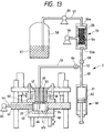
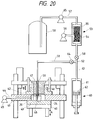
- FIG. 13 shows an ink filling apparatus 200, constructed in accordance with one embodiment of the invention, which includes a table 40 for supporting pallet 20.
- Table 40 can be vertically actuated in the direction indicated by a double arrow F by means of a drive mechanism (not shown).
- container body 1 remains seated in pallet 20 in its upright position.
- a bed 41 having a through hole 41a, formed to accommodate container body 1, is positioned on raised section 24.
- An injection chamber 43 is formed in through hole 41a by the combination of pallet 20, which forms a lower surface of chamber 43, and a cover member 42 which forms on upper surface of chamber 43.
- Injection chamber 43 is connected to a vacuum pump 45 via a channel 44 formed in bed 41.
- a through hole 46 is formed in cover member 42 so as to oppose injection chamber 43.
- a piston 47 is inserted into through hole 46, and is constructed to maintain injection chamber 43 in an air-tight state while moving vertically in a direction indicated by a double arrow G.
- Piston 47 includes an injection needle 48, positioned to face ink injection ports 100, 101, 102 of container body 1, set in injection chamber 43, and a channel 50, which faces atmospheric communication ports 190, 191, 192 of container body 1, and is connected to an air supply device (not shown).
- Injection needle 48 is connected to a branch tube 52 via a channel 49 formed in piston 47, a tube 51, and a stop valve 64.
- Ink filling apparatus 200 also includes a gas-liquid separation unit 53.
- gas-liquid separation unit 53 includes a hollow yarn bundle 54, which is preferably connected fluid-tight at both longitudinal ends to a cylinder 55 so as to permit fluid to flow therethrough.
- Cylinder 55 is connected to a vacuum pump 56 so as to produce negative pressure around the outer periphery of yarn bundle 54.
- Cylinder 55 includes an inlet 55a, which is connected to an ink tank 58 having ink 67 therein, via a tube 57, and an outlet 55b, which is connected to branch pipe 52 via a stop valve 58.
- Branch pipe 52 is also connected to a measuring tube 60 via a tube 63.
- Measuring tube 60 includes a cylinder 61 and a piston 62, and is preferably connected to branch pipe 52 at the center of one end of cylinder 61.
- container body 1 After container body 1 has been assembled, it is transported on pallet 20 to ink injection apparatus 200, and is set below injection chamber 43, as is shown in FIG. 14A.
- Table 40 is then raised in a direction H until raised portion 24 of pallet 20 comes into close contact with a lower surface of bed 41, as shown in FIG. 14B.
- piston 47 is lowered such that a gap exists between piston 47 and cover 11 of container body 1 and piston 47 forms a seal with cover member 42.
- Stop valve 64 is then opened while maintaining stop valve 58 connected to the gas-liquid separation unit 60 in a closed position.
- Vacuum pump 45 which is connected via channel 44 to injection chamber 43, is then activated to depressurize injection chamber 43, tubes 51 and 63, and measuring tube 60 to a predetermined pressure.
- stop valve 64 is closed. Thereafter, measuring tube 60 is placed in fluid communication with gas-liquid separation unit 53 by opening stop valve 58, and a predetermined quantity of ink 67 is filled into measuring tube 60.
- piston member 47 is lowered such that packing members 65, 66 formed on the lower end of piston member 47 are brought into elastic contact with ink injection port 100 and atmospheric port 190 of container body 1, respectively.
- injection needle 48 is positioned in fluid communication with container body 1, as it is inserted through ink inlet port 100 into the vicinity of the bottom of container body 1. Since gas-liquid separation unit 53 is connected close to measuring tube 60, ink flows into measuring tube 60 immediately after having been degassed by gas-liquid separation unit 53.
- stop valve 58 is closed to isolate gas-liquid separation unit 53, stop valve 64 is opened, and piston 62 of measuring tube 60 is pressed to discharge the predetermined quantity of ink 67 into foam chamber 160 via ink injection port 100.
- ink 67 which has been completely degassed by gas-liquid separation unit 53, is absorbed into porous member 150.
- gas trapped in the pores of porous member 150 that were not discharged in the foregoing depressurization stop readily dissolves into ink 67. Therefore, ink 67 is uniformly absorbed by porous member 150 without causing air bubbles to form in porous member 150.
- foam chamber 160 When foam chamber 160 is filled with ink 67, air bubbles do not exist in at least porous members 150, and because air bubbles are not introduced via channel 50, ink 67 provided to the recording head via the porous member 150 is free of bubbles, thereby ensuring print quality.
- the remaining foam chambers 161, 162 are filled with ink by a similar process.
- channel 50 is opened to ambient air, so that ink 67 that remains on an upper part of porous member 150 is completely absorbed into porous member 150 by means of the pressure differential between the pressure in porous member 150 and ambient pressure.
- table 40 is lowered, and pallet 20 is transported to the next assembly station.
- the other porous members can be filled with ink in a similar fashion.
- the ink that has adhered to ink injection port 100 during the filling process is wiped off by vacuum suction or with a cloth.
- a conduit (not shown) is brought into contact with ink injection port 100, and a very small positive suction is applied to the conduit, thereby suctioning the ink adhered to the reverse side of cover 11.
- container body 1 is housed in a depressurization container 38 and is inclined in such a way that exhausting ports 190, 191, 192 face upward.
- Seal 19 is formed so as to cover at least exhaustion ports 190, 191, 192, the ink inlet ports 100, 101, 102 and grooves 170, 171, 172, and can be temporarily adhered to cover 11 by heat welding or otherwise.
- seal 19 covering grooves 170, 171, 172 is heated, so that a part of seal 19 is welded to the surface of cover 11 thereby forming capillaries.
- the principle portion of the remainder of seal 19 is adhered to cover 11 such that it can be readily peeled away from cover 11.
- ink-filled ink cartridge 70 at least ink ejection ports 180, 181, 182 are bought into contact with a buffer 71 so as to prevent seals 16 from rupturing. Further, tongue 19a of seal 19 is folded, and ink cartridge 70 is then inserted into a bag 72, which is preferably formed from a gas-insulating film, and has a collar 72a. Collar 72a is arranged near the opening of bag 72, and is folded inwardly to a uniform thickness. The opening of bag 72 is heat welded in a vacuum environment as shown in FIG 17A. Finally, the packaged ink cartridge 70 is inserted into a case 73, and is ready to be shipped as a product (FIG. 17B).
- the present invention has been described with reference to the cartridge having multiple ink chambers, the present invention can be applied to the manufacture of an ink cartridge 75 such as that shown in FIG. 18, where ink is only filled into porous member 5 housed in container body 1'.
- a small cartridge 76 having a body 1'' shown in FIG. 19 only one opening 77 may be formed in a cartridge 76 so as to serve as an ink inlet port and an atmospheric communication port.
- ink injection needle 48 and channel 50 connected to the exhaust device are provided coaxially with respect to each other.
- one opening 77 can be used both for ink injection and air exhaust operations.
- the present invention provides a method of manufacturing an ink cartridge for use in an ink jet recorder, including the steps of: setting on a pellet a substantially rectangular container body, having an opening, so that the bottom surface of the container body faces upward, the container body including porous members formed from resilient material for absorbing ink, foam chambers for incorporating the porous members therein, and ink ejection ports formed in the bottom surface of the foam chambers; inserting a packing member into each of the ink ejection ports and heat-welding sealing film to the ink ejection port openings; resetting the container body on the pellet by turning it upside down to its uptight position; affixing filter material to the entrance side of the ink ejection port; pressing the compressed porous member into each of the foam chambers; forming the container by bonding a cover to the opening of the container body; filling a specified quantity of ink into each of the foam chambers while the container or is held in a vacuum environment; and bonding a seal to the surface of
Landscapes
- Engineering & Computer Science (AREA)
- Manufacturing & Machinery (AREA)
- Ink Jet (AREA)
Applications Claiming Priority (3)
| Application Number | Priority Date | Filing Date | Title |
|---|---|---|---|
| JP318696/96 | 1996-11-14 | ||
| JP8318696A JPH10138507A (ja) | 1996-11-14 | 1996-11-14 | インクジェット式記録装置用インクカートリッジの製造方法 |
| JP31869696 | 1996-11-14 |
Publications (3)
| Publication Number | Publication Date |
|---|---|
| EP0842780A2 true EP0842780A2 (fr) | 1998-05-20 |
| EP0842780A3 EP0842780A3 (fr) | 1999-06-16 |
| EP0842780B1 EP0842780B1 (fr) | 2002-03-27 |
Family
ID=18101994
Family Applications (1)
| Application Number | Title | Priority Date | Filing Date |
|---|---|---|---|
| EP97309203A Expired - Lifetime EP0842780B1 (fr) | 1996-11-14 | 1997-11-14 | Procédé de fabrication d'une cartouche d'encre utilisable avec un appareil d'enregistrement par jet d'encre |
Country Status (6)
| Country | Link |
|---|---|
| US (2) | US5875615A (fr) |
| EP (1) | EP0842780B1 (fr) |
| JP (1) | JPH10138507A (fr) |
| CN (2) | CN1082896C (fr) |
| DE (1) | DE69711330T2 (fr) |
| TW (1) | TW359643B (fr) |
Cited By (7)
| Publication number | Priority date | Publication date | Assignee | Title |
|---|---|---|---|---|
| EP0997293A3 (fr) * | 1998-10-27 | 2000-10-18 | Canon Kabushiki Kaisha | Procédé pour insérer un absorbant dans un récipient et conteneur ainsi obtenu |
| EP1090766A1 (fr) * | 1999-10-05 | 2001-04-11 | Nec Corporation | Cartouche d'encre, procédé de fabrication de celle-ci et appareil d'enregistrement à jet d'encre |
| EP1127695A1 (fr) * | 2000-02-22 | 2001-08-29 | Canon Kabushiki Kaisha | Procédé de fabrication du réservoir d'encre, réservoir d'encre, cartouche et appareil d'enregistrement à jet d'encre |
| EP1177906A3 (fr) * | 2000-07-14 | 2002-06-05 | Xerox Corporation | Cartouche d'encre |
| CN102514381A (zh) * | 2011-12-02 | 2012-06-27 | 珠海天威飞马打印耗材有限公司 | 喷墨打印机墨盒的扩容方法 |
| CN106042019A (zh) * | 2016-05-19 | 2016-10-26 | 张帆 | 一种打印机墨盒的小海绵切割方法 |
| CN108349255A (zh) * | 2015-12-21 | 2018-07-31 | 惠普发展公司,有限责任合伙企业 | 液体吸收 |
Families Citing this family (57)
| Publication number | Priority date | Publication date | Assignee | Title |
|---|---|---|---|---|
| JP3402351B2 (ja) * | 1996-08-05 | 2003-05-06 | セイコーエプソン株式会社 | インクジェット式記録装置 |
| JPH10250104A (ja) * | 1997-03-12 | 1998-09-22 | Seiko Epson Corp | インクジェット式記録装置用インクカートリッジ、及びその製造方法 |
| US6027199A (en) * | 1997-12-19 | 2000-02-22 | Lexmark International, Inc. | Ink jet cartridge system and method of printing using plurality of same color inks with different intensities |
| US6270207B1 (en) * | 1998-03-30 | 2001-08-07 | Brother Kogyo Kabushiki Kaisha | Ink cartridge and remaining ink volume detection method |
| JP2001199082A (ja) * | 1999-10-08 | 2001-07-24 | Seiko Epson Corp | インクカートリッジ、インクジェット記録装置、及びインクカートリッジの装着方法 |
| CN1278862C (zh) * | 1999-10-12 | 2006-10-11 | 精工爱普生株式会社 | 用于喷墨打印设备的墨盒 |
| US6095401A (en) * | 1999-12-21 | 2000-08-01 | Lexmark International, Inc. | System and method for supression of bubble generation during ultrasonic welding of a printer cartridge |
| JP2001212977A (ja) | 2000-02-02 | 2001-08-07 | Seiko Epson Corp | インクカートリッジの製造方法 |
| USD448797S1 (en) | 2000-07-14 | 2001-10-02 | Xerox Corporation | Ink tank |
| US6250749B1 (en) * | 2000-07-14 | 2001-06-26 | Xerox Corporation | Ink cartridge with overflow conduit |
| US6742880B2 (en) * | 2000-10-06 | 2004-06-01 | Nu-Kote International, Inc. | Dual chamber cartridge |
| AU2002213042A1 (en) * | 2000-10-06 | 2002-04-15 | Nu-Kote International, Inc. | Multiple-chamber cartridge with varying porous member compression |
| AU2002214554A1 (en) * | 2000-10-06 | 2002-04-15 | Nu-Kote International, Inc. | Geometric ink channels for ink cartridge |
| AU2002211473A1 (en) * | 2000-10-06 | 2002-04-15 | Nu-Kote International, Inc. | Maximum liquid level in dual chamber ink-jet cartridge to control head pressure effect on ink containing porous member in an ink-jet printer |
| AU2002211488A1 (en) * | 2000-10-06 | 2002-04-15 | Nu-Kote International, Inc. | Dual chamber ink-jet cartridge |
| WO2002028715A1 (fr) | 2000-10-06 | 2002-04-11 | Nu-Kote International Inc | Methode de remplissage d"encre sous pression |
| US6923530B2 (en) * | 2001-06-13 | 2005-08-02 | Nu-Kote International, Inc. | Fused filter screen for use in ink jet cartridge and method of assembling same |
| US6814433B2 (en) * | 2001-06-13 | 2004-11-09 | Nu-Kote International, Inc. | Base aperture in ink jet cartridge with irregular edges for breaking surface tension of the ink |
| US6682183B2 (en) | 2001-06-13 | 2004-01-27 | Nu-Kote International, Inc. | Seal member for ink jet cartridge |
| US6749293B1 (en) | 2001-06-13 | 2004-06-15 | Nu-Kote International, Inc. | Full liquid version of ink jet cassette for use with ink jet printer |
| US6447109B1 (en) | 2001-07-13 | 2002-09-10 | Xerox Corporation | Liquid ink cartridge and improved filling method |
| US6533396B2 (en) * | 2001-08-16 | 2003-03-18 | Benq Corporation | Printhead cartridge with asymmetrical contacts |
| US6786583B2 (en) * | 2001-08-30 | 2004-09-07 | Seiko Epson Corporation | Ink cartridge storage structure and method |
| DE10202365A1 (de) | 2002-01-17 | 2003-07-31 | Pelikan Hardcopy Production Ag | Tintenbehälter mit Schwamm und Verfahren zu dessen Herstellung |
| JP2004009475A (ja) * | 2002-06-06 | 2004-01-15 | Hitachi Printing Solutions Ltd | インクジェット記録装置及びそれに用いるインク供給装置 |
| US6969165B2 (en) * | 2003-02-24 | 2005-11-29 | Hewlett-Packard Development Company, L.P. | Ink reservoirs |
| US7258434B2 (en) * | 2003-11-24 | 2007-08-21 | Lexmark International, Inc. | Inkjet printheads having multiple label placement positions for air diffusion vents |
| RU2288104C2 (ru) * | 2003-12-26 | 2006-11-27 | Кэнон Кабусики Кайся | Контейнер для жидкости и способ его изготовления |
| JP4058434B2 (ja) | 2003-12-26 | 2008-03-12 | キヤノン株式会社 | インク収納容器、該容器の製造方法およびプリンタシステム |
| US7219980B2 (en) * | 2004-01-21 | 2007-05-22 | Silverbrook Research Pty Ltd | Printhead assembly with removable cover |
| CN2691854Y (zh) * | 2004-02-06 | 2005-04-13 | 珠海天威飞马打印耗材有限公司 | 恒压连续供墨器 |
| US7416294B2 (en) * | 2004-02-19 | 2008-08-26 | Fujifilm Corporation | Image forming apparatus and liquid control method |
| CN100340408C (zh) * | 2004-04-01 | 2007-10-03 | 国际联合科技股份有限公司 | 墨盒 |
| JP3840237B2 (ja) * | 2004-06-02 | 2006-11-01 | キヤノン株式会社 | 液体収納容器および該液体収納容器を用いた記録装置 |
| CN2763042Y (zh) * | 2005-01-19 | 2006-03-08 | 珠海纳思达电子科技有限公司 | 一种喷墨打印机墨盒使用的密封件 |
| WO2006112209A1 (fr) * | 2005-03-30 | 2006-10-26 | Seiko Epson Corporation | Dispositif d'ejection de liquide |
| KR20070116933A (ko) * | 2005-03-30 | 2007-12-11 | 세이코 엡슨 가부시키가이샤 | 액체 용기 |
| US7399073B2 (en) * | 2005-05-19 | 2008-07-15 | Hewlett-Packard Development Company, L.P. | Ink supply |
| US8132904B2 (en) | 2005-12-21 | 2012-03-13 | Lexmark International, Inc. | Filter/wicking structure for micro-fluid ejection head |
| US8517524B1 (en) * | 2006-01-30 | 2013-08-27 | Shahar Turgeman | Ink jet printer cartridge refilling method and apparatus |
| US9718268B1 (en) | 2006-01-30 | 2017-08-01 | Shahar Turgeman | Ink printing system comprising groups of inks, each group having a unique ink base composition |
| US10144222B1 (en) | 2006-01-30 | 2018-12-04 | Shahar Turgeman | Ink printing system |
| DE102006026258A1 (de) * | 2006-06-02 | 2007-12-06 | Artech Gmbh Design + Production In Plastic | Tintenkartusche |
| JP4928892B2 (ja) * | 2006-09-29 | 2012-05-09 | 富士フイルム株式会社 | インクジェット記録装置 |
| CN101152795B (zh) * | 2006-09-30 | 2010-11-10 | 珠海天威飞马打印耗材有限公司 | 喷墨打印机墨盒再生方法 |
| US7748832B2 (en) * | 2006-12-29 | 2010-07-06 | Markem-Imaje Corporation | Printing apparatuses and related apparatuses and methods |
| US8322835B2 (en) * | 2007-02-19 | 2012-12-04 | Seiko Epson Corporation | Sealing structure of fluid container, and method of manufacturing and reusing fluid container |
| JP2008230214A (ja) * | 2007-02-19 | 2008-10-02 | Seiko Epson Corp | 流体導出部のシール構造体及びシール方法並びに流体収容容器、再充填流体収容容器及びその再充填方法 |
| TWI327111B (en) * | 2007-04-20 | 2010-07-11 | Hon Hai Prec Ind Co Ltd | Apparatus for adjusting negative pressure of ink tank and ink-supplying system |
| CN101332720B (zh) * | 2008-07-31 | 2010-06-09 | 李支斌 | 一种打印机供墨托架及其供墨框架与系统 |
| JP2011177917A (ja) * | 2010-02-26 | 2011-09-15 | Canon Inc | インクジェットカートリッジの製造方法 |
| JP5780785B2 (ja) | 2011-03-11 | 2015-09-16 | キヤノン株式会社 | 負圧発生部材の挿入方法および負圧発生部材挿入装置 |
| JP4894971B1 (ja) * | 2011-06-29 | 2012-03-14 | 富士ゼロックス株式会社 | 脱気装置及び画像形成装置 |
| US8864293B2 (en) | 2012-09-12 | 2014-10-21 | Xerox Corporation | Phase change ink reservoir for a phase change inkjet printer |
| CN106004066B (zh) * | 2016-05-19 | 2018-03-09 | 张帆 | 墨盒小海绵组装方法 |
| CN110304317B (zh) * | 2019-03-27 | 2021-03-26 | 重庆中烟工业有限责任公司 | 一种片烟分格式包装装置 |
| CN111267494B (zh) * | 2020-02-27 | 2021-04-02 | 宁波润爵科技有限公司 | 一种用于打印机墨盒的装配设备 |
Family Cites Families (17)
| Publication number | Priority date | Publication date | Assignee | Title |
|---|---|---|---|---|
| JP3513979B2 (ja) * | 1994-09-16 | 2004-03-31 | セイコーエプソン株式会社 | インクジェットプリンタ用インクカートリッジ |
| EP0578331B1 (fr) * | 1989-09-18 | 1997-12-29 | Canon Kabushiki Kaisha | Méthode de remplissage d'une cartouche d'encre pour appareil d'enregistrement à jet d'encre |
| DE69118489T2 (de) * | 1990-11-30 | 1996-08-14 | Canon Kk | Tintenbehälter und Aufzeichnungskopf mit einem solchen Behälter |
| US5790158A (en) * | 1992-01-28 | 1998-08-04 | Seiko Epson Corporation | Ink-jet recording apparatus and ink tank cartridge therefor |
| US5477963A (en) * | 1992-01-28 | 1995-12-26 | Seiko Epson Corporation | Ink-jet recording apparatus and ink tank cartridge therefor |
| CA2101017C (fr) * | 1992-07-24 | 1999-10-26 | Masahiko Higuma | Cartouche d'encre, tete d'imprimante a jet d'encre et imprimante a jet d'encre |
| DE4327178C1 (de) * | 1993-08-13 | 1995-03-09 | Pms Gmbh Prod & Recycling | Vorrichtung zum Wiederbefüllen eines Druckkopfs eines Tintenstrahldruckers |
| US5479968A (en) * | 1993-08-16 | 1996-01-02 | Xerox Corporation | Ink filling apparatus and method for filling ink cartridges |
| DE69424724T2 (de) * | 1993-08-31 | 2000-11-23 | Canon K.K., Tokio/Tokyo | Verfahren und Gerät zum Befüllen von Tintenpatronen mit Tinte |
| US5400573A (en) * | 1993-12-14 | 1995-03-28 | Crystal; Richard G. | Kit and method for opening, refilling and sealing a cartridge |
| JP3101482B2 (ja) * | 1994-01-31 | 2000-10-23 | キヤノン株式会社 | 液体保持容器の製造方法、及び製造装置 |
| US5659345A (en) * | 1994-10-31 | 1997-08-19 | Hewlett-Packard Company | Ink-jet pen with one-piece pen body |
| JP3347559B2 (ja) * | 1994-12-28 | 2002-11-20 | キヤノン株式会社 | インクタンク及びインクジェットカートリッジならびにインクジェット記録装置 |
| JP3308751B2 (ja) * | 1995-02-21 | 2002-07-29 | キヤノン株式会社 | インクタンク及びその製造方法 |
| US5953030A (en) * | 1995-04-24 | 1999-09-14 | Canon Kabushiki Kaisha | Ink container with improved air venting structure |
| US5734400A (en) * | 1995-10-31 | 1998-03-31 | Brunetti; Bruce W. | Method and apparatus for refilling ink jet unit printer cartridges |
| US5732751A (en) * | 1995-12-04 | 1998-03-31 | Hewlett-Packard Company | Filling ink supply containers |
-
1996
- 1996-11-14 JP JP8318696A patent/JPH10138507A/ja active Pending
-
1997
- 1997-11-13 CN CN97125263A patent/CN1082896C/zh not_active Expired - Fee Related
- 1997-11-13 CN CN02102784.6A patent/CN1236920C/zh not_active Expired - Fee Related
- 1997-11-13 TW TW086117061A patent/TW359643B/zh not_active IP Right Cessation
- 1997-11-14 EP EP97309203A patent/EP0842780B1/fr not_active Expired - Lifetime
- 1997-11-14 US US08/969,862 patent/US5875615A/en not_active Expired - Lifetime
- 1997-11-14 DE DE69711330T patent/DE69711330T2/de not_active Expired - Lifetime
-
1998
- 1998-11-23 US US09/198,173 patent/US6250746B1/en not_active Expired - Lifetime
Cited By (13)
| Publication number | Priority date | Publication date | Assignee | Title |
|---|---|---|---|---|
| US6505925B2 (en) | 1998-10-27 | 2003-01-14 | Canon Kabushiki Kaisha | Method for inserting absorbent into container and container receiving absorbent produced by the method |
| US6286947B1 (en) | 1998-10-27 | 2001-09-11 | Canon Kabushiki Kaisha | Method for inserting an absorbent into a container and container receiving an absorbent produced by the method |
| EP0997293A3 (fr) * | 1998-10-27 | 2000-10-18 | Canon Kabushiki Kaisha | Procédé pour insérer un absorbant dans un récipient et conteneur ainsi obtenu |
| EP1090766A1 (fr) * | 1999-10-05 | 2001-04-11 | Nec Corporation | Cartouche d'encre, procédé de fabrication de celle-ci et appareil d'enregistrement à jet d'encre |
| EP1127695A1 (fr) * | 2000-02-22 | 2001-08-29 | Canon Kabushiki Kaisha | Procédé de fabrication du réservoir d'encre, réservoir d'encre, cartouche et appareil d'enregistrement à jet d'encre |
| US6435675B2 (en) | 2000-02-22 | 2002-08-20 | Canon Kabushiki Kaisha | Method for manufacturing ink tank, ink tank, ink jet cartridge, and ink jet recording apparatus |
| EP1177906A3 (fr) * | 2000-07-14 | 2002-06-05 | Xerox Corporation | Cartouche d'encre |
| CN102514381A (zh) * | 2011-12-02 | 2012-06-27 | 珠海天威飞马打印耗材有限公司 | 喷墨打印机墨盒的扩容方法 |
| CN108349255A (zh) * | 2015-12-21 | 2018-07-31 | 惠普发展公司,有限责任合伙企业 | 液体吸收 |
| EP3337665A4 (fr) * | 2015-12-21 | 2019-04-03 | Hewlett-Packard Development Company, L.P. | Adsorption de liquide |
| CN108349255B (zh) * | 2015-12-21 | 2020-05-29 | 惠普发展公司,有限责任合伙企业 | 液体吸收系统、包装的液体分配设备和液体吸收方法 |
| CN106042019A (zh) * | 2016-05-19 | 2016-10-26 | 张帆 | 一种打印机墨盒的小海绵切割方法 |
| CN106042019B (zh) * | 2016-05-19 | 2018-04-10 | 张帆 | 一种打印机墨盒的小海绵切割方法 |
Also Published As
| Publication number | Publication date |
|---|---|
| CN1082896C (zh) | 2002-04-17 |
| EP0842780A3 (fr) | 1999-06-16 |
| EP0842780B1 (fr) | 2002-03-27 |
| DE69711330D1 (de) | 2002-05-02 |
| CN1396058A (zh) | 2003-02-12 |
| TW359643B (en) | 1999-06-01 |
| JPH10138507A (ja) | 1998-05-26 |
| CN1236920C (zh) | 2006-01-18 |
| US6250746B1 (en) | 2001-06-26 |
| CN1192405A (zh) | 1998-09-09 |
| US5875615A (en) | 1999-03-02 |
| HK1009422A1 (en) | 1999-06-04 |
| DE69711330T2 (de) | 2002-07-18 |
Similar Documents
| Publication | Publication Date | Title |
|---|---|---|
| US5875615A (en) | Method of manufacturing an ink cartridge for use in ink jet recorder | |
| US6854834B2 (en) | Ink cartridge for ink-jet recorder and method of manufacturing same | |
| US7393089B2 (en) | Method of refilling an ink cartridge for use in ink jet recorder | |
| HK1009422B (en) | Method of manufacturing an ink cartridge for use in ink-jet recorder | |
| JP2005186478A (ja) | 液体収容体及び液体収容体の製造方法 | |
| HK1029965B (en) | Method of manufacturing ink cartridge for ink-jet recorder | |
| HK1029964B (en) | Ink cartridge for ink-jet recorder and method of manufacturing same | |
| JP2000158662A (ja) | インクジェット式記録装置用インクカートリッジの製造方法 | |
| HK1032771B (en) | Cartridge for ink-jet recorder | |
| JP3596617B2 (ja) | インクカートリッジの製造方法 | |
| JP2003063031A (ja) | インクカートリッジの製造方法 | |
| JP4000604B2 (ja) | インクカートリッジの製造方法 | |
| JP4167961B2 (ja) | インクカートリッジ | |
| JPH10329329A (ja) | インクジェット記録装置用インクカートリッジ | |
| HK1041850A1 (en) | A method of manufacturing an ink cartridge for use in an ink jet recorder |
Legal Events
| Date | Code | Title | Description |
|---|---|---|---|
| PUAI | Public reference made under article 153(3) epc to a published international application that has entered the european phase |
Free format text: ORIGINAL CODE: 0009012 |
|
| AK | Designated contracting states |
Kind code of ref document: A2 Designated state(s): DE FR GB IT |
|
| AX | Request for extension of the european patent |
Free format text: AL;LT;LV;MK;RO;SI |
|
| RIN1 | Information on inventor provided before grant (corrected) |
Inventor name: NISHIMURA, TAEKO Inventor name: KOIKE, HISASHI Inventor name: HONZAWA, TADATOSHI Inventor name: SATO, MASAKAZU Inventor name: NAKAMURA, YUICHI Inventor name: MATSUYAMA, MASAHIDE Inventor name: TAKADA, SEIICHI Inventor name: ITO, KAZUNORI |
|
| PUAL | Search report despatched |
Free format text: ORIGINAL CODE: 0009013 |
|
| AK | Designated contracting states |
Kind code of ref document: A3 Designated state(s): AT BE CH DE DK ES FI FR GB GR IE IT LI LU MC NL PT SE |
|
| AX | Request for extension of the european patent |
Free format text: AL;LT;LV;MK;RO;SI |
|
| 17P | Request for examination filed |
Effective date: 19991110 |
|
| AKX | Designation fees paid |
Free format text: DE FR GB IT |
|
| GRAG | Despatch of communication of intention to grant |
Free format text: ORIGINAL CODE: EPIDOS AGRA |
|
| 17Q | First examination report despatched |
Effective date: 20010607 |
|
| GRAG | Despatch of communication of intention to grant |
Free format text: ORIGINAL CODE: EPIDOS AGRA |
|
| GRAH | Despatch of communication of intention to grant a patent |
Free format text: ORIGINAL CODE: EPIDOS IGRA |
|
| GRAH | Despatch of communication of intention to grant a patent |
Free format text: ORIGINAL CODE: EPIDOS IGRA |
|
| REG | Reference to a national code |
Ref country code: GB Ref legal event code: IF02 |
|
| GRAA | (expected) grant |
Free format text: ORIGINAL CODE: 0009210 |
|
| AK | Designated contracting states |
Kind code of ref document: B1 Designated state(s): DE FR GB IT |
|
| REF | Corresponds to: |
Ref document number: 69711330 Country of ref document: DE Date of ref document: 20020502 |
|
| ET | Fr: translation filed | ||
| PLBE | No opposition filed within time limit |
Free format text: ORIGINAL CODE: 0009261 |
|
| STAA | Information on the status of an ep patent application or granted ep patent |
Free format text: STATUS: NO OPPOSITION FILED WITHIN TIME LIMIT |
|
| 26N | No opposition filed |
Effective date: 20021230 |
|
| PGFP | Annual fee paid to national office [announced via postgrant information from national office to epo] |
Ref country code: IT Payment date: 20101115 Year of fee payment: 14 |
|
| PG25 | Lapsed in a contracting state [announced via postgrant information from national office to epo] |
Ref country code: IT Free format text: LAPSE BECAUSE OF NON-PAYMENT OF DUE FEES Effective date: 20121114 |
|
| REG | Reference to a national code |
Ref country code: FR Ref legal event code: PLFP Year of fee payment: 19 |
|
| PGFP | Annual fee paid to national office [announced via postgrant information from national office to epo] |
Ref country code: GB Payment date: 20151111 Year of fee payment: 19 Ref country code: DE Payment date: 20151110 Year of fee payment: 19 |
|
| PGFP | Annual fee paid to national office [announced via postgrant information from national office to epo] |
Ref country code: FR Payment date: 20151008 Year of fee payment: 19 |
|
| REG | Reference to a national code |
Ref country code: DE Ref legal event code: R119 Ref document number: 69711330 Country of ref document: DE |
|
| GBPC | Gb: european patent ceased through non-payment of renewal fee |
Effective date: 20161114 |
|
| REG | Reference to a national code |
Ref country code: FR Ref legal event code: ST Effective date: 20170731 |
|
| PG25 | Lapsed in a contracting state [announced via postgrant information from national office to epo] |
Ref country code: FR Free format text: LAPSE BECAUSE OF NON-PAYMENT OF DUE FEES Effective date: 20161130 |
|
| PG25 | Lapsed in a contracting state [announced via postgrant information from national office to epo] |
Ref country code: DE Free format text: LAPSE BECAUSE OF NON-PAYMENT OF DUE FEES Effective date: 20170601 Ref country code: GB Free format text: LAPSE BECAUSE OF NON-PAYMENT OF DUE FEES Effective date: 20161114 |