EP0842785B1 - Verfahren zum Betrieb eines Thermodruckers - Google Patents
Verfahren zum Betrieb eines Thermodruckers Download PDFInfo
- Publication number
- EP0842785B1 EP0842785B1 EP97307971A EP97307971A EP0842785B1 EP 0842785 B1 EP0842785 B1 EP 0842785B1 EP 97307971 A EP97307971 A EP 97307971A EP 97307971 A EP97307971 A EP 97307971A EP 0842785 B1 EP0842785 B1 EP 0842785B1
- Authority
- EP
- European Patent Office
- Prior art keywords
- ribbon
- width
- spool
- elements
- Prior art date
- Legal status (The legal status is an assumption and is not a legal conclusion. Google has not performed a legal analysis and makes no representation as to the accuracy of the status listed.)
- Expired - Lifetime
Links
- 238000000034 method Methods 0.000 title claims description 17
- 239000000758 substrate Substances 0.000 claims abstract description 26
- 239000005022 packaging material Substances 0.000 abstract description 2
- 238000004806 packaging method and process Methods 0.000 description 4
- 238000010586 diagram Methods 0.000 description 2
- 230000000694 effects Effects 0.000 description 2
- 239000000463 material Substances 0.000 description 2
- 230000006835 compression Effects 0.000 description 1
- 238000007906 compression Methods 0.000 description 1
- 230000009977 dual effect Effects 0.000 description 1
- 230000000977 initiatory effect Effects 0.000 description 1
- 230000003287 optical effect Effects 0.000 description 1
Images


Classifications
-
- B—PERFORMING OPERATIONS; TRANSPORTING
- B41—PRINTING; LINING MACHINES; TYPEWRITERS; STAMPS
- B41J—TYPEWRITERS; SELECTIVE PRINTING MECHANISMS, i.e. MECHANISMS PRINTING OTHERWISE THAN FROM A FORME; CORRECTION OF TYPOGRAPHICAL ERRORS
- B41J33/00—Apparatus or arrangements for feeding ink ribbons or like character-size impression-transfer material
- B41J33/14—Ribbon-feed devices or mechanisms
- B41J33/54—Ribbon-feed devices or mechanisms for ensuring maximum life of the ribbon
-
- B—PERFORMING OPERATIONS; TRANSPORTING
- B41—PRINTING; LINING MACHINES; TYPEWRITERS; STAMPS
- B41J—TYPEWRITERS; SELECTIVE PRINTING MECHANISMS, i.e. MECHANISMS PRINTING OTHERWISE THAN FROM A FORME; CORRECTION OF TYPOGRAPHICAL ERRORS
- B41J17/00—Mechanisms for manipulating page-width impression-transfer material, e.g. carbon paper
- B41J17/02—Feeding mechanisms
- B41J17/12—Special adaptations for ensuring maximum life
Definitions
- This invention relates to a method of operating a thermal printer in which ink is transferred to a substrate from a thermal print ribbon.
- European Patent Specification No. 0734876A discloses a thermal printer for printing information such as dates and bar codes on packaging material, label-bearing films and other substrates by thermal transfer of ink from a thermal print ribbon using a thermal print head having a line of selectively energisable print elements which are brought to bear against a moving ribbon with the ribbon being sandwiched between the print head and the substrate which is to bear the printed information.
- the ribbon is fed to the printing region from a supply spool via one or more deflection rollers, and is collected via one or more further deflection rollers on a take-up spool, and once the full length of the ribbon is depleted of ink, a new spool of unused ribbon is fitted to the machine.
- spindles for receiving the supply and take-up spools are mounted on a removable cassette unit which includes the above-mentioned deflection rollers.
- Ribbon replacement is effected by removing the cassette unit from the printer body, removing the supply and take-up spools from the cassette unit, fitting a new supply spool with unused ribbon to the relevant spindle on the cassette unit, threading the free end of the ribbon around the deflection rollers and on to an empty take-up spool, and then sliding the cassette unit back onto the printer body, whereby the ribbon automatically takes up the correct position with respect to the thermal print head and the path of travel of the substrate material.
- Ribbons of different widths may be used, depending on the transverse width of the area to be printed, i.e. in the direction transversely of the ribbon.
- the applicants have found that the tendency for the ribbon to break increases as the ribbon width is reduced.
- excessive compression of the take-up spool can occur, leading to difficulty in removing it from the printer.
- GB-A-2272669 discloses a printer that uses a double width ink ribbon in a cassette, which is mounted initially in a first orientation to enable transfer of ink from a first half of the width of the ribbon. After the fall length of the ribbon has been used, the cassette is mounted in a reversed orientation so that ink can be transferred from the other half of the width of the ribbon.
- the elements of the print head of the printer extend across substantially the entire width of the ribbon.
- US-A-4641149 discloses a thermal transfer printer for printing with an ink ribbon in plural columns, in which initially printing is carried out in the upper half of the ribbon, then the ribbon cassette is reviewed to effect printing in the other half of the ribbon.
- a method of operating a thermal printer in which ink is transferred from a single- use thermal print ribbon to a substrate by energising print elements of a thermal print head at a printing station, wherein the ribbon is fed along a path from a supply position to a take-up position through the printing station in a first run whereby print elements are energised such that ink is depleted only in a longitudinal strip of the ribbon, the width of the strip being no greater than half the width of the ribbon, wherein the ribbon is inverted and is fed through the printing station in a second print run whereby the said print elements are energised such that ink is depleted from a longitudinal strip in the other half of the ribbon, characterised in that in the first run the ribbon is fed from a first spool acting as a supply spool to a second spool acting as a take-up spool, the second spool containing the partially-depleted ribbon is removed, turned through 180 degrees
- the first and second spools are positioned on a ribbon-mounting structure of the printer on opposite sides of the printing station, wherein an unused reel of ribbon is wound on the first spool in the supply position with one edge of the ribbon adjacent the ribbon-mounting structure for the first printing run, and wherein subsequently the second spool bearing the partially-depleted ribbon is removed from the take-up position and mounted in the supply position with the said one edge of the ribbon remote from the ribbon-mounting structure, in preparation for the second print run.
- the group of print elements energised are of such an extent and position with respect to the ribbon as to define an ink depletion strip which is between the respective ribbon edge and a centre line of the ribbon and spaced from both that edge and the centre line by respective guard bands.
- the energised print elements In the conventional use of a thermal printer, it is normal to confine the energised print elements to a width which is somewhat less than the total width of the ribbon so as to provide guards bands adjacent each edge of the ribbon, thereby allowing for ribbon alignment tolerances.
- the guard band adjacent the centre line of the ribbon may be much reduced in width, effecting a further reduction in ribbon wastage.
- the invention also includes a thermal printer and a print ribbon carrying out any of the above described methods, the printer comprising a print head having print elements that extend across substantially the entire width of the ribbon when passing therethrough, and means confining energisation of the print elements to only those print elements in registry with part of the width of the ribbon, the said part having width no greater then one half of the width of the ribbon.
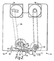
- a printer for the continuous printing of a continuous print medium by transfer from a thermal transfer print ribbon has a base unit and a removable ribbon cassette unit 12.
- the base unit which is mounted to a frame of the printer (not shown) contains a print head stepper motor 14 and a ribbon drive stepper motor 18.
- a pivotable print head carrier 20 supports a print head 22 and is coupled to the motor 14 by way of a parallelogram linkage including a connection link 26.
- Ribbon spools 34, 36 are detachably and rotatably mounted on a front plate 38 of the cassette unit 12, and when the cassette unit 12 is fitted to the base unit 10, they are coextensive with the print head 22 in terms of their location in a direction perpendicular to the plate 38. Also attached to the cassette unit front plate 38 is a ribbon drive roller 32 visible in Figure 1 below ribbon spool 34, and also in Figure 3.
- the relative positioning of the ribbon spools 34, 36, the print head 22, and a ribbon drive roller 40 may be ascertained by comparison of Figure 1 with Figure 3.
- the ribbon 42 itself is shown in full lines in Figure 3, but in phantom lines in Figure 1 for clarity.
- a platen roller 44 and a deflection roller 46 shown in Figure 2 are mounted on the printer frame or other apparatus with which the printer is associated.
- a continuous film substrate 50 on which information is to be printed enters the printer in an inlet region 52, passes over and wraps around the platen roller 44, from where it follows a downward inclined path to pass underneath and wrap around the deflection roller 46 before passing to an outlet region 54 of the printer.
- Both platen roller 44 and deflection roller 46 have axes of rotation which extend at right angles to the direction of travel of the substrate 50.
- the thermal transfer ribbon 42 travels in the same direction as the substrate 50 and follows a ribbon path from supply spool 36 via deflector rollers 58, 64, and 66, thence through a printing region which, when the cassette unit 12 is loaded into the base unit 10, lies between the print head 22 and the platen 44.
- the ribbon then passes over further guides 68, 70, and via drive roller 40 and pinch roller 72 onto the take-up spool 38, which is belt driven by a belt 76 from a pulley 78 mounted on the shaft of drive roller 40.
- the ribbon 42 passes over the platen 44, it is in frictional contact with the substrate film 50.
- the ribbon 42 is held in contact with the substrate film 50 only between the start and finish of each printing operation during which the lower surface of the print head 22 bears against the platen 44 through ribbon 42 and film 50 as shown in Figure 2. At other times, the print head 22 is raised by operation of its stepper motor 14.
- the print head 22 has side-facing printing elements 82 ( Figure 2) extending along a line parallel to the axis of rotation 84 of the print head carrier 20. These printing elements 82 project from a lower surface 86 of the print head 22.
- the ribbon 42 and the substrate film 50 are pinched between the print head 22 and the platen roller 44 precisely at the line of printing elements 82, and when these elements are heated under electronic control and the film 50 and ribbon 22 are passed together in the same direction over the elements, ink is transferred from the ribbon 42 to the film 50 to print characters and symbols according to pre-programmed information incorporated in the signals fed to the print head 22.
- An optical shaft encoder on a shaft bearing the platen roller 44 produces a signal representative of the speed of the film substrate 50 and by processing this output signal, the stepper motor 18 driving the ribbon drive roller 40 can be adjusted such that the ribbon is driven at a required speed.
- the shaft encoder associated with the platen roller 44 is shown in Figure 4 by reference numeral 90.
- Encoder 90 provides an input signal representative of film speed to an input 92 of a processor unit 94.
- the processor unit has at its heart a microprocessor, and has three outputs comprising output 96 for a first motor driver circuit 98 for raising and lowering the print head, a second output which is a multiwire output 100 coupled to the energisable elements 82 of the print head 22, and a third output 102 for a ribbon motor driver 104 for controlling ribbon stepper motor 18.
- Other inputs to the processor include a trigger input 106 for receiving a trigger signal initiating each printing operation which is typically generated by sensing the position of products to which the substrate film 50 is to be applied as packaging as the products travel along an adjacent conveyor.
- Another input 108 receives the information to be printed from a memory 110 according to an input design.
- the processor is programmed firstly to move the print head 22 to its extended position, to start the ribbon drive motor, and to initiate printing by energising the elements of the print head 22 in accordance with the information stored in the memory 110 thereby to print the information as a pattern or a series of characters in a designated print area on the substrate film 50.
- the processor When the processor senses that all the information relating to the required design has been supplied from memory 110 and has been fed to the print head 22, it issues a stop signal to the ribbon driver 104 to stop ribbon travel, and the driver 98 for the print head motor 14 receives a signal causing the motor to withdraw the print head to its retracted, inactive position.
- a ribbon status sensor 116 associated with a pivotable arm 120 (see Figure 3) in the cassette unit detects when the ribbon supply runs low so that an alarm can be activated and/or operation of the packaging apparatus of which the printer is part can be halted.
- a break sensor 118 responsive to excessive clockwise movement of arm 60 (see Figure 3) to sense breakage of the ribbon 42.
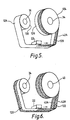
- the width of the ribbon 42 depends on the width of the area to be printed. However, in accordance with the invention, it is advantageous in the case of a comparatively narrow printed area to provide a ribbon 42 of a width which is at least twice the width of the printed area and then to use two longitudinal halves of the ribbon successively, as will now be explained with reference to Figures 5 to 7.
- the limited transverse extent of the energised elements creates a strip 120 of depleted ribbon which occupies just under one half of the width of the ribbon 42 adjacent a first edge 42A, as shown in Figure 5.
- This mode of operation is continued until the supply spool 36 is exhausted and substantially all of the ribbon is wound onto the second spool 34, here acting as a take-up spool.
- the take-up spool 34 is removed from its mounting on the cassette unit 12, the empty supply spool 36 is also removed, and then the second spool 34 is turned through 180° about an axis perpendicular to its axis of rotation and placed on the spindle formerly occupied by the supply spool 36 so that the second spool 34 becomes the new supply spool as shown in Figure 6. Since the ribbon has been inverted by the rotation of the spool 34 through 180°, the first edge 42A now lies in the opposite position with respect to its position during the first print run shown in Figure 5, i.e. at the other end of the print head 22. The undepleted portion of the ribbon 42 wound on spool 34 is now available for printing, using the same group of printer head elements as was used during the first print run.
- a second print run may now be commenced, as shown in Figure 6, whereby the above-mentioned group of elements is in registry with the undepleted part of the ribbon 42 adjacent its second edge 42B, and printing may be carried on until the ribbon is once again exhausted, this time the ribbon 42 being wound up on an empty spool 40 mounted on the cassette unit 12 in the position formerly occupied by the second spool 34, as shown in Figure 6.
- both the supply spool and the take-up spool rotate in the same direction throughout, in this case in an anticlockwise direction as seen in Figures 5 and 6.
- the path of the ribbon 42 instead of extending from the sides 124, 126 (see Figure 5) of the ribbon reels which are remote from each other, may extend from the inner sides 128, 130, with the spools rotating in the clockwise direction. In the latter case, it is still possible to obtain the dual use of the ribbon illustrated in Figure 6.
- the spools 34, 36 are open-ended in the sense that they may be fitted in either of two orientations on the printer mounting spindles, i.e. with either end of the tubular core facing the ribbon mounting structure from which the spindles project.
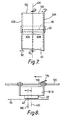
- the print head 22 is shown diagrammatically in Figures 5 to 7.
- the print head elements 82 are shown by dotted lines.
- Figure 7 is, effectively, an underside view of the ribbon during the second print run, and also shows the print head elements 82A which are energised during the first and second print runs. As will be seen, these extend over no more than one half of the width of the ribbon 42.
- the first and second print runs are performed with only elements of the group 82A being energised, it is possible to extend the life of the print head when it is used solely for printing in print areas of a width which is less than half of the ribbon width by using instead a second group 82B of elements when the elements of group 82A show signs of wear.
- This repositioning of the printer is shown diagrammatically in Figure 8 in which the printer is shown by references 10, 12 and positioned above a substrate 50.
- Printer 10, 12 is mounted on support rails 130 associated with, for example, packaging apparatus by means of sliding bearings 132.
- the centre line of a box image to be printed on the substrate is indicated by reference 50C and with the printer 10, 12 in the position shown, the image is printed using the left-hand side of the print head 22 as seen in Figure 8.
- bearing lock 134 is released and printer 10, 12 is moved leftwards on rails 130 so that the centre line 42C of the ribbon, which is also the centre line of the print head 22, is moved to the other side of the box image centre line 50C, thereby bringing the elements of the right-hand side of the print head 22 into registry with the box image position.
- the bearing lock is then operated again to lock the printer 10, 12 in the new position on rails 130.
- the print head 22 remains fixed in its position longitudinally over the ribbon and both the ribbon and the substrate move relative to the head during printing.
- the substrate 50 is a continuous film of material which moves at a continuous rate.
- the invention may also be put into effect in an intermittent printer, i.e. one in which the substrate and the ribbon remain stationary during printing whilst the print head 22 is caused to move longitudinally of the ribbon during each printing operation.
- the exchange and inversion of the ribbon spools is the same as described above.
Landscapes
- Impression-Transfer Materials And Handling Thereof (AREA)
- Electronic Switches (AREA)
- Accessory Devices And Overall Control Thereof (AREA)
Claims (8)
- Verfahren zum Betrieb eines Thermodruckers, bei dem Druckfarbe von einem einmal verwendbaren Thermodruckband auf ein Substrat übertragen wird, indem Druckelemente eines Thermodruckkopfes an einer Druckstation zugeschaltet werden, wobei das Band in einem ersten Lauf längs eines Weges von einer Zuführposition durch die Druckstation zu einer Aufwickelstation geführt wird, wodurch Druckelemente derart zugeschaltet werden, daß Druckfarbe nur in einem Längsstreifen des Bandes aufgebraucht wird, wobei die Breite des Streifens nicht größer als die halbe Breite des Bandes ist, wobei das Band umgekehrt wird und in einem zweiten Drucklauf durch die Druckstation geführt wird, wodurch die Druckelemente derart zugeschaltet werden, daß Druckfarbe von einem Längsstreifen in der anderen Hälfte des Bandes aufgebraucht wird, dadurch gekennzeichnet, daß das Band in dem ersten Lauf von einer als Zuführspule wirkenden Spule zu einer als Aufwickelspule wirkenden zweiten Spule geführt wird, die das zum Teil erschöpfte Band enthaltende zweite Spule entfernt wird, zum Umkehren des Bandes um 180 Grad gedreht wird und an der Stelle der ersten Spule befestigt wird, um als neue Zuführspule zu wirken, und das Band in dem zweiten Lauf von der neuen Zuführspule zu einer neuen Aufwickelspule geführt wird; daß der Drucker so angeordnet ist, daß der Druckkopf sich im wesentlichen quer über die gesamte Breite des Bandes erstreckende Druckelemente aufweist; und daß bei dem ersten und dem zweiten Drucklauf nur ausgewählte von den Druckelementen zugeschaltet werden, die auf eine Gruppe begrenzt sind, die in einer quer zu dem Band über nicht mehr als die halbe Breite des Bandes verlaufenden Linie angeordnet sind.
- Verfahren nach Anspruch 1, wobei die erste und die zweite Spule an einer das Band befestigenden Konstruktion des Druckers auf einander gegenüberliegenden Seiten der Druckstation positioniert sind, wobei eine nicht verwendete Rolle des Bandes auf die erste Spule in der Zuführposition gewickelt wird, wobei für den ersten Drucklauf ein Rand des Bandes angrenzend an die das Band befestigende Konstruktion liegt, und wobei anschließend die das zum Teil erschöpfte Band tragende zweite Spule von der Aufwickelposition entfernt wird und in der Zuführposition befestigt wird, wobei der eine Rand des Bandes bei der Vorbereitung auf den zweiten Drucklauf von der das Band befestigenden Konstruktion entfernt liegt.
- Verfahren nach Anspruch 1 oder Anspruch 2, wobei die Gruppe der Elemente einen solchen Umfang und eine solche Stellung in bezug auf das Band aufweist, daß sie einen Druckfarbenaufbrauchstreifen bildet, der sich zwischen dem jeweiligen Rand des Bandes und einer Mittellinie des Bandes befindet und sowohl von dem jeweiligen Rand als auch von den jeweiligen Schutzstreifen beabstandet ist.
- Verfahren nach Anspruch 3, wobei die Breite des an die Mittellinie angrenzenden Schutzstreifens kleiner als die Breite des an den Rand angrenzenden Schutzstreifens ist.
- Verfahren nach Anspruch 4, wobei die Breite des an die Mittellinie angrenzenden Schutzstreifens kleiner als die oder gleich der halben Breite des an den Rand angrenzenden Schutzstreifens ist.
- Verfahren nach einem der Ansprüche 2 bis 5, wobei der Drucker nach dem erfolgten ersten und zweiten Drucklauf umkonfiguriert wird, um eine zweite, keine Elemente der ersten Gruppe enthaltende Gruppe der Druckkopfelemente zu verwenden, um weitere erste und zweite Druckläufe auszuführen, wobei die jeweilige Position des Druckers und des Substrats verschoben wird, um die durch die Umkonfigurierung zustandegekommene Änderung in der Druckposition auszugleichen.
- Verfahren nach Anspruch 6, wobei die Umkonfigurierung des Druckers erfolgt, nachdem mehrere aufeinanderfolgende Paare der ersten und zweiten Druckläufe ausgeführt sind.
- Thermodrucker und Druckband zum Ausführen eines Verfahrens nach einem der Ansprüche 1 bis 7, wobei der Drucker einen Druckkopf mit Druckelementen, die sich quer über im wesentlichen die gesamte Breite des Bandes erstreckt, wenn dieses hindurchläuft, und ein Mittel umfaßt, das das Zuschalten der Druckelemente nur auf diejenigen Druckelemente begrenzt, die mit einem Teil der Breite des Bandes registergleich sind, wobei der Teil eine Breite aufweist, die nicht größer als eine halbe Breite des Bandes ist.
Applications Claiming Priority (3)
| Application Number | Priority Date | Filing Date | Title |
|---|---|---|---|
| GB9621475 | 1996-10-15 | ||
| GBGB9621475.4A GB9621475D0 (en) | 1996-10-15 | 1996-10-15 | A method of operating a thermal printer |
| US08/951,012 US6019527A (en) | 1996-10-15 | 1997-10-15 | Method of operating a thermal printer |
Publications (2)
| Publication Number | Publication Date |
|---|---|
| EP0842785A1 EP0842785A1 (de) | 1998-05-20 |
| EP0842785B1 true EP0842785B1 (de) | 2002-03-27 |
Family
ID=26310233
Family Applications (1)
| Application Number | Title | Priority Date | Filing Date |
|---|---|---|---|
| EP97307971A Expired - Lifetime EP0842785B1 (de) | 1996-10-15 | 1997-10-08 | Verfahren zum Betrieb eines Thermodruckers |
Country Status (8)
| Country | Link |
|---|---|
| US (1) | US6019527A (de) |
| EP (1) | EP0842785B1 (de) |
| AT (1) | ATE215017T1 (de) |
| AU (1) | AU691781B2 (de) |
| CA (1) | CA2218224C (de) |
| DE (1) | DE69711331T2 (de) |
| ES (1) | ES2173392T3 (de) |
| GB (1) | GB9621475D0 (de) |
Families Citing this family (12)
| Publication number | Priority date | Publication date | Assignee | Title |
|---|---|---|---|---|
| GB2343655B (en) | 1998-11-13 | 2002-12-24 | Markem Tech Ltd | Method of printing |
| AU2001286048A1 (en) | 2000-09-11 | 2002-03-26 | Zipher Limited | Tape drive and printing apparatus |
| KR100727934B1 (ko) * | 2005-04-12 | 2007-06-14 | 삼성전자주식회사 | 프린터 헤드의 수명 연장을 위한 프린트 방법, 이를 위한프린터, 호스트 및 프린트 시스템 |
| US7417656B1 (en) | 2005-12-06 | 2008-08-26 | Cognitive Solutions, Inc. | Compact printer |
| US20070273746A1 (en) * | 2006-05-26 | 2007-11-29 | Cognitive Solutions, Inc. | Multiple media, multiple print head method and apparatus |
| US20080124161A1 (en) * | 2006-06-30 | 2008-05-29 | Cognitive Solutions, Inc. | Hybrid desktop-portable printer method and apparatus |
| GB2448302B (en) | 2007-03-07 | 2009-04-08 | Zipher Ltd | Tape drive |
| EP2134549B1 (de) | 2007-03-31 | 2014-11-19 | Videojet Technologies, Inc. | Bandantrieb |
| KR101285243B1 (ko) * | 2012-11-19 | 2013-07-12 | 주식회사 딜리 | 디지털 인쇄용 피출력물 공급회수장치 |
| JP7035966B2 (ja) * | 2018-10-31 | 2022-03-15 | ブラザー工業株式会社 | 印刷システム |
| WO2021049009A1 (ja) * | 2019-09-13 | 2021-03-18 | 大日本印刷株式会社 | 熱転写印画装置、印画物の製造方法、及び中間転写媒体 |
| CN118107292B (zh) * | 2024-02-04 | 2024-09-03 | 广州市科帕电子科技有限公司 | 热转印打印机及其打印控制方法 |
Family Cites Families (42)
| Publication number | Priority date | Publication date | Assignee | Title |
|---|---|---|---|---|
| US4008795A (en) * | 1972-10-20 | 1977-02-22 | Ing. C. Olivetti & C., S.P.A. | Removable cartridge for the inked ribbon for typewriters, calculating machines or other office machines |
| EP0036308B1 (de) * | 1980-03-13 | 1984-07-18 | Nec Corporation | Patrone für ein Farbband für einen Schlagdrucker |
| JPS58140260A (ja) * | 1982-02-16 | 1983-08-19 | Hitachi Ltd | 印字装置 |
| JPS58153666A (ja) * | 1982-03-09 | 1983-09-12 | セイコーエプソン株式会社 | ドツトプリンタ |
| US4528576A (en) * | 1982-04-15 | 1985-07-09 | Canon Kabushiki Kaisha | Recording apparatus |
| US4933867A (en) * | 1983-05-31 | 1990-06-12 | Kabushiki Kaisha Toshiba | Printing apparatus |
| US4614949A (en) * | 1983-10-20 | 1986-09-30 | Ricoh Company, Ltd. | Transfer-type thermal printer |
| JPS60116478A (ja) * | 1983-11-30 | 1985-06-22 | Eimaa Denshi Kk | カラーサーマルラインプリンタ |
| JPS60190380A (ja) * | 1984-03-13 | 1985-09-27 | Hitachi Ltd | 熱転写プリンタ |
| US4568210A (en) * | 1984-03-30 | 1986-02-04 | Wang Laboratories, Inc. | Reversible ribbon cartridge |
| JPS6135274A (ja) * | 1984-07-27 | 1986-02-19 | Brother Ind Ltd | カラ−印字装置 |
| JPS6157359A (ja) * | 1984-08-29 | 1986-03-24 | Hitachi Ltd | 熱転写プリンタ |
| JPS61104877A (ja) * | 1984-10-29 | 1986-05-23 | Ricoh Co Ltd | ライン熱転写記録装置の駆動機構 |
| US4563691A (en) * | 1984-12-24 | 1986-01-07 | Fuji Xerox Co., Ltd. | Thermo-sensitive recording apparatus |
| JPS61154868A (ja) * | 1984-12-27 | 1986-07-14 | Minolta Camera Co Ltd | サ−マルプリンタ |
| EP0194694B1 (de) * | 1985-03-15 | 1992-09-30 | Hitachi, Ltd. | Bandkassette für Drucker |
| JPS61262171A (ja) * | 1985-05-16 | 1986-11-20 | Mitsubishi Electric Corp | カラ−インクリボン |
| JPS6277633A (ja) * | 1985-09-30 | 1987-04-09 | Hitachi Ltd | プリンタ制御装置 |
| US4740092A (en) * | 1986-07-14 | 1988-04-26 | International Business Machines Corporation | Printhead shifting for wear distribution |
| US4717924A (en) * | 1986-08-18 | 1988-01-05 | Ncr Corporation | Thermal printing control system |
| JPH0630449Y2 (ja) * | 1986-09-08 | 1994-08-17 | ブラザー工業株式会社 | 印字装置 |
| US4929099A (en) * | 1988-01-19 | 1990-05-29 | Qume Corporation | Multi-line serial printer |
| GB8804467D0 (en) * | 1988-02-25 | 1988-03-23 | Alcatel Business Systems | Thermal printing apparatus |
| DE3806935A1 (de) * | 1988-03-03 | 1989-09-14 | Standard Elektrik Lorenz Ag | Drucker |
| KR920006490B1 (ko) * | 1988-07-01 | 1992-08-07 | 가부시끼가이샤 히다찌세이사꾸쇼 | 열전자 기록장치 |
| US5369422A (en) * | 1988-09-22 | 1994-11-29 | Canon Kabushiki Kaisha | Thermal transfer recording method in which an ink sheet is moved at a selected speed and apparatus for performing the same |
| FR2642004B1 (fr) * | 1988-12-30 | 1995-02-03 | Oce Graphics France | Imprimante thermique grande largeur |
| JPH03130179A (ja) * | 1989-07-20 | 1991-06-03 | Canon Inc | 熱転写記録装置及び熱転写記録方法 |
| US5138335A (en) * | 1989-10-16 | 1992-08-11 | Tokyo Electric Co., Ltd. | Thermal printer with removable ribbon unit |
| US5121136A (en) * | 1990-03-20 | 1992-06-09 | Ricoh Company, Ltd. | Recorder for thermal transfer recording operations |
| US5162815A (en) * | 1990-06-25 | 1992-11-10 | Eastman Kodak Company | Thermal printing apparatus with tensionless donor web during printing |
| DE4110776A1 (de) * | 1991-03-28 | 1992-10-01 | Mannesmann Ag | Verfahren zum aufzeichnen von informationen |
| US5429443A (en) * | 1992-04-06 | 1995-07-04 | Alp Electric Co., Ltd. | Thermal transfer printer with ink ribbon feed controller |
| GB2272669B (en) * | 1992-11-20 | 1996-09-25 | Neopost Ltd | Printing apparatus |
| US5372439A (en) * | 1992-12-18 | 1994-12-13 | Zebra Technologies Corporation | Thermal transfer printer with controlled ribbon feed |
| JPH06278334A (ja) * | 1993-01-27 | 1994-10-04 | Ricoh Co Ltd | 熱転写プリンタ |
| US5445463A (en) * | 1993-03-30 | 1995-08-29 | Paranjpe; Suresh C. | Combination ink or dye ribbon for nonimpact printing |
| US5611629A (en) * | 1993-03-30 | 1997-03-18 | Paranjpe; Suresh C. | Multiple print head nonimpact printing apparatus |
| EP0646469A3 (de) * | 1993-09-24 | 1996-05-15 | Esselte Meto Int Gmbh | Druckmaschine. |
| DE69517089T2 (de) * | 1994-05-20 | 2000-11-02 | Markem Technologies Ltd., Nottingham | Druckverfahren mit wirtschaftlicher Ausnutzung des Übertragungsmaterials |
| EP0635368A3 (de) * | 1994-05-26 | 1995-09-06 | Illinois Tool Works | Verfahren und Gerät für kostengünstigen Thermo-Drucker. |
| GB9506651D0 (en) * | 1995-03-31 | 1995-05-24 | Itw Ltd | A printer for printing on a continuous print medium |
-
1996
- 1996-10-15 GB GBGB9621475.4A patent/GB9621475D0/en active Pending
-
1997
- 1997-10-08 ES ES97307971T patent/ES2173392T3/es not_active Expired - Lifetime
- 1997-10-08 DE DE69711331T patent/DE69711331T2/de not_active Expired - Lifetime
- 1997-10-08 AT AT97307971T patent/ATE215017T1/de not_active IP Right Cessation
- 1997-10-08 EP EP97307971A patent/EP0842785B1/de not_active Expired - Lifetime
- 1997-10-09 AU AU39993/97A patent/AU691781B2/en not_active Ceased
- 1997-10-14 CA CA002218224A patent/CA2218224C/en not_active Expired - Fee Related
- 1997-10-15 US US08/951,012 patent/US6019527A/en not_active Expired - Lifetime
Also Published As
| Publication number | Publication date |
|---|---|
| US6019527A (en) | 2000-02-01 |
| DE69711331T2 (de) | 2004-04-22 |
| CA2218224A1 (en) | 1998-04-15 |
| MX9707916A (es) | 1998-08-30 |
| DE69711331D1 (de) | 2002-05-02 |
| AU3999397A (en) | 1998-04-23 |
| EP0842785A1 (de) | 1998-05-20 |
| ES2173392T3 (es) | 2002-10-16 |
| GB9621475D0 (en) | 1996-12-04 |
| CA2218224C (en) | 2003-07-22 |
| ATE215017T1 (de) | 2002-04-15 |
| AU691781B2 (en) | 1998-05-21 |
Similar Documents
| Publication | Publication Date | Title |
|---|---|---|
| EP0842785B1 (de) | Verfahren zum Betrieb eines Thermodruckers | |
| US5971634A (en) | Method of printing | |
| CA1276834C (en) | Thermal transfer ribbon mechanism and recording method | |
| EP0113701B1 (de) | Drucker für Verkaufsstelle | |
| EP0861735B1 (de) | Drucker zum Bedrucken von einem bandförmigen Aufzeichnungsträger | |
| US5177505A (en) | Ink jet printer print head cleaning apparatus and method | |
| US5993092A (en) | Printer with reversible ribbon driving means for rewinding overshot ribbon | |
| EP0805044B1 (de) | Thermischer Drucker und Verfahren | |
| GB2383974A (en) | Thermal ribbon printing apparatus having first and second motors for driving a print head and a used ribbon spool respectively | |
| US6247859B1 (en) | Method of printing in which the print head and print ribbon move simultaneously in the same direction | |
| CA2173083A1 (en) | A printer for printing on a continuous print medium | |
| MXPA97003229A (en) | Thermal printer and met | |
| MXPA97007916A (en) | Method for operating a term printer | |
| JPH06127063A (ja) | 感熱プリンタにおけるドナーウェブ位置決め装置 | |
| EP0816108B1 (de) | Drucker zum Bedrucken von einem bandförmigen Aufzeichnungsträger | |
| CA1061763A (en) | Paper drive mechanism | |
| JPH10166629A (ja) | ラベルプリンタ | |
| EP0930171B1 (de) | Farbbandvorschub | |
| JP3236884B2 (ja) | 捺染機の着尺用バッチアップロール | |
| JPH10157173A (ja) | プリンタ | |
| JP3066203U (ja) | 印字装置 | |
| JPS5936469Y2 (ja) | 印刷装置 | |
| JPS6266982A (ja) | 抵抗リボン式印字装置 | |
| JPH04128084A (ja) | プリンタ | |
| JPH0999545A (ja) | 印刷機の元ローラ及びインキ壺洗浄方法 |
Legal Events
| Date | Code | Title | Description |
|---|---|---|---|
| PUAI | Public reference made under article 153(3) epc to a published international application that has entered the european phase |
Free format text: ORIGINAL CODE: 0009012 |
|
| AK | Designated contracting states |
Kind code of ref document: A1 Designated state(s): AT BE CH DE DK ES FI FR GB GR IE IT LI LU NL PT SE |
|
| 17P | Request for examination filed |
Effective date: 19980619 |
|
| AKX | Designation fees paid |
Free format text: AT BE CH DE DK ES FI FR GB GR IE IT LI LU NL PT SE |
|
| RBV | Designated contracting states (corrected) |
Designated state(s): AT BE CH DE DK ES FI FR GB GR IE IT LI LU NL PT SE |
|
| 17Q | First examination report despatched |
Effective date: 19990716 |
|
| GRAG | Despatch of communication of intention to grant |
Free format text: ORIGINAL CODE: EPIDOS AGRA |
|
| GRAG | Despatch of communication of intention to grant |
Free format text: ORIGINAL CODE: EPIDOS AGRA |
|
| GRAH | Despatch of communication of intention to grant a patent |
Free format text: ORIGINAL CODE: EPIDOS IGRA |
|
| REG | Reference to a national code |
Ref country code: GB Ref legal event code: IF02 |
|
| GRAH | Despatch of communication of intention to grant a patent |
Free format text: ORIGINAL CODE: EPIDOS IGRA |
|
| GRAA | (expected) grant |
Free format text: ORIGINAL CODE: 0009210 |
|
| AK | Designated contracting states |
Kind code of ref document: B1 Designated state(s): AT BE CH DE DK ES FI FR GB GR IE IT LI LU NL PT SE |
|
| PG25 | Lapsed in a contracting state [announced via postgrant information from national office to epo] |
Ref country code: NL Free format text: LAPSE BECAUSE OF FAILURE TO SUBMIT A TRANSLATION OF THE DESCRIPTION OR TO PAY THE FEE WITHIN THE PRESCRIBED TIME-LIMIT Effective date: 20020327 Ref country code: LI Free format text: LAPSE BECAUSE OF FAILURE TO SUBMIT A TRANSLATION OF THE DESCRIPTION OR TO PAY THE FEE WITHIN THE PRESCRIBED TIME-LIMIT Effective date: 20020327 Ref country code: IT Free format text: LAPSE BECAUSE OF FAILURE TO SUBMIT A TRANSLATION OF THE DESCRIPTION OR TO PAY THE FEE WITHIN THE PRE;WARNING: LAPSES OF ITALIAN PATENTS WITH EFFECTIVE DATE BEFORE 2007 MAY HAVE OCCURRED AT ANY TIME BEFORE 2007. THE CORRECT EFFECTIVE DATE MAY BE DIFFERENT FROM THE ONE RECORDED.SCRIBED TIME-LIMIT Effective date: 20020327 Ref country code: GR Free format text: LAPSE BECAUSE OF FAILURE TO SUBMIT A TRANSLATION OF THE DESCRIPTION OR TO PAY THE FEE WITHIN THE PRESCRIBED TIME-LIMIT Effective date: 20020327 Ref country code: FI Free format text: LAPSE BECAUSE OF FAILURE TO SUBMIT A TRANSLATION OF THE DESCRIPTION OR TO PAY THE FEE WITHIN THE PRESCRIBED TIME-LIMIT Effective date: 20020327 Ref country code: CH Free format text: LAPSE BECAUSE OF FAILURE TO SUBMIT A TRANSLATION OF THE DESCRIPTION OR TO PAY THE FEE WITHIN THE PRESCRIBED TIME-LIMIT Effective date: 20020327 Ref country code: BE Free format text: LAPSE BECAUSE OF FAILURE TO SUBMIT A TRANSLATION OF THE DESCRIPTION OR TO PAY THE FEE WITHIN THE PRESCRIBED TIME-LIMIT Effective date: 20020327 Ref country code: AT Free format text: LAPSE BECAUSE OF FAILURE TO SUBMIT A TRANSLATION OF THE DESCRIPTION OR TO PAY THE FEE WITHIN THE PRESCRIBED TIME-LIMIT Effective date: 20020327 |
|
| REF | Corresponds to: |
Ref document number: 215017 Country of ref document: AT Date of ref document: 20020415 Kind code of ref document: T |
|
| REG | Reference to a national code |
Ref country code: CH Ref legal event code: EP |
|
| REF | Corresponds to: |
Ref document number: 69711331 Country of ref document: DE Date of ref document: 20020502 |
|
| REG | Reference to a national code |
Ref country code: IE Ref legal event code: FG4D |
|
| PG25 | Lapsed in a contracting state [announced via postgrant information from national office to epo] |
Ref country code: SE Free format text: LAPSE BECAUSE OF FAILURE TO SUBMIT A TRANSLATION OF THE DESCRIPTION OR TO PAY THE FEE WITHIN THE PRESCRIBED TIME-LIMIT Effective date: 20020627 Ref country code: PT Free format text: LAPSE BECAUSE OF FAILURE TO SUBMIT A TRANSLATION OF THE DESCRIPTION OR TO PAY THE FEE WITHIN THE PRESCRIBED TIME-LIMIT Effective date: 20020627 Ref country code: DK Free format text: LAPSE BECAUSE OF FAILURE TO SUBMIT A TRANSLATION OF THE DESCRIPTION OR TO PAY THE FEE WITHIN THE PRESCRIBED TIME-LIMIT Effective date: 20020627 |
|
| ET | Fr: translation filed | ||
| NLV1 | Nl: lapsed or annulled due to failure to fulfill the requirements of art. 29p and 29m of the patents act | ||
| REG | Reference to a national code |
Ref country code: CH Ref legal event code: PL |
|
| PG25 | Lapsed in a contracting state [announced via postgrant information from national office to epo] |
Ref country code: LU Free format text: LAPSE BECAUSE OF NON-PAYMENT OF DUE FEES Effective date: 20021008 |
|
| REG | Reference to a national code |
Ref country code: ES Ref legal event code: FG2A Ref document number: 2173392 Country of ref document: ES Kind code of ref document: T3 |
|
| PGFP | Annual fee paid to national office [announced via postgrant information from national office to epo] |
Ref country code: IE Payment date: 20030106 Year of fee payment: 6 |
|
| PLBE | No opposition filed within time limit |
Free format text: ORIGINAL CODE: 0009261 |
|
| STAA | Information on the status of an ep patent application or granted ep patent |
Free format text: STATUS: NO OPPOSITION FILED WITHIN TIME LIMIT |
|
| 26N | No opposition filed |
Effective date: 20021230 |
|
| PG25 | Lapsed in a contracting state [announced via postgrant information from national office to epo] |
Ref country code: IE Free format text: LAPSE BECAUSE OF NON-PAYMENT OF DUE FEES Effective date: 20031008 |
|
| REG | Reference to a national code |
Ref country code: IE Ref legal event code: MM4A |
|
| PGFP | Annual fee paid to national office [announced via postgrant information from national office to epo] |
Ref country code: ES Payment date: 20091026 Year of fee payment: 13 Ref country code: DE Payment date: 20091028 Year of fee payment: 13 |
|
| PGFP | Annual fee paid to national office [announced via postgrant information from national office to epo] |
Ref country code: GB Payment date: 20091026 Year of fee payment: 13 Ref country code: FR Payment date: 20091029 Year of fee payment: 13 |
|
| GBPC | Gb: european patent ceased through non-payment of renewal fee |
Effective date: 20101008 |
|
| PG25 | Lapsed in a contracting state [announced via postgrant information from national office to epo] |
Ref country code: FR Free format text: LAPSE BECAUSE OF NON-PAYMENT OF DUE FEES Effective date: 20101102 |
|
| REG | Reference to a national code |
Ref country code: FR Ref legal event code: ST Effective date: 20110630 |
|
| PG25 | Lapsed in a contracting state [announced via postgrant information from national office to epo] |
Ref country code: GB Free format text: LAPSE BECAUSE OF NON-PAYMENT OF DUE FEES Effective date: 20101008 |
|
| REG | Reference to a national code |
Ref country code: DE Ref legal event code: R119 Ref document number: 69711331 Country of ref document: DE Effective date: 20110502 |
|
| REG | Reference to a national code |
Ref country code: ES Ref legal event code: FD2A Effective date: 20111118 |
|
| PG25 | Lapsed in a contracting state [announced via postgrant information from national office to epo] |
Ref country code: ES Free format text: LAPSE BECAUSE OF NON-PAYMENT OF DUE FEES Effective date: 20101009 |
|
| PG25 | Lapsed in a contracting state [announced via postgrant information from national office to epo] |
Ref country code: DE Free format text: LAPSE BECAUSE OF NON-PAYMENT OF DUE FEES Effective date: 20110502 |