EP0843183B1 - Abtastbildaufnahmegerät und ein Abtastlaserempfänger - Google Patents
Abtastbildaufnahmegerät und ein Abtastlaserempfänger Download PDFInfo
- Publication number
- EP0843183B1 EP0843183B1 EP97309313A EP97309313A EP0843183B1 EP 0843183 B1 EP0843183 B1 EP 0843183B1 EP 97309313 A EP97309313 A EP 97309313A EP 97309313 A EP97309313 A EP 97309313A EP 0843183 B1 EP0843183 B1 EP 0843183B1
- Authority
- EP
- European Patent Office
- Prior art keywords
- scanning
- optical system
- laser beam
- image pick
- optical
- Prior art date
- Legal status (The legal status is an assumption and is not a legal conclusion. Google has not performed a legal analysis and makes no representation as to the accuracy of the status listed.)
- Expired - Lifetime
Links
Images




Classifications
-
- H—ELECTRICITY
- H04—ELECTRIC COMMUNICATION TECHNIQUE
- H04N—PICTORIAL COMMUNICATION, e.g. TELEVISION
- H04N3/00—Scanning details of television systems; Combination thereof with generation of supply voltages
- H04N3/02—Scanning details of television systems; Combination thereof with generation of supply voltages by optical-mechanical means only
- H04N3/08—Scanning details of television systems; Combination thereof with generation of supply voltages by optical-mechanical means only having a moving reflector
-
- G—PHYSICS
- G03—PHOTOGRAPHY; CINEMATOGRAPHY; ANALOGOUS TECHNIQUES USING WAVES OTHER THAN OPTICAL WAVES; ELECTROGRAPHY; HOLOGRAPHY
- G03B—APPARATUS OR ARRANGEMENTS FOR TAKING PHOTOGRAPHS OR FOR PROJECTING OR VIEWING THEM; APPARATUS OR ARRANGEMENTS EMPLOYING ANALOGOUS TECHNIQUES USING WAVES OTHER THAN OPTICAL WAVES; ACCESSORIES THEREFOR
- G03B17/00—Details of cameras or camera bodies; Accessories therefor
- G03B17/02—Bodies
- G03B17/17—Bodies with reflectors arranged in beam forming the photographic image, e.g. for reducing dimensions of camera
-
- G—PHYSICS
- G02—OPTICS
- G02B—OPTICAL ELEMENTS, SYSTEMS OR APPARATUS
- G02B26/00—Optical devices or arrangements for the control of light using movable or deformable optical elements
- G02B26/08—Optical devices or arrangements for the control of light using movable or deformable optical elements for controlling the direction of light
- G02B26/10—Scanning systems
-
- G—PHYSICS
- G02—OPTICS
- G02B—OPTICAL ELEMENTS, SYSTEMS OR APPARATUS
- G02B27/00—Optical systems or apparatus not provided for by any of the groups G02B1/00 - G02B26/00, G02B30/00
- G02B27/10—Beam splitting or combining systems
- G02B27/14—Beam splitting or combining systems operating by reflection only
-
- G—PHYSICS
- G02—OPTICS
- G02B—OPTICAL ELEMENTS, SYSTEMS OR APPARATUS
- G02B27/00—Optical systems or apparatus not provided for by any of the groups G02B1/00 - G02B26/00, G02B30/00
- G02B27/28—Optical systems or apparatus not provided for by any of the groups G02B1/00 - G02B26/00, G02B30/00 for polarising
- G02B27/283—Optical systems or apparatus not provided for by any of the groups G02B1/00 - G02B26/00, G02B30/00 for polarising used for beam splitting or combining
Definitions
- the present invention relates to a scanning type image pick-up apparatus and a scanning type laser beam receive apparatus suitable for passively or actively scanning a wide view-field by a two-dimensional manner.
- an image pick-up camera internally including an image pick-up element of a charge storing type is used to obtain a light wave.
- the image pick-up element has a view angle 0 and therefore, a method of scanning a search range to take in a the view image is adopted in case of searching a wide view.
- the image pick-up element is provided at a focus position of an optical system, and image data is obtained by taking in light waves of a visible region (e.g., 0.4 ⁇ m to 0.8 ⁇ m) and an infrared region (e.g., 3 ⁇ m to 12 ⁇ m) received by the optical system and performing photoelectric conversion thereon. Therefore, if an angle range equivalent to an instant view angle of one pixel of the image pick-up element is scanned in one direction at a speed faster than the speed at which the image pick-up element is exposed, a so-called image flow is caused and the view image obtained thereby becomes unclear.
- a visible region e.g., 0.4 ⁇ m to 0.8 ⁇ m
- an infrared region e.g., 3 ⁇ m to 12 ⁇ m
- a conventional scanning type image pick-up apparatus adopts a reflection mirror step scanning method in which a reflection mirror is provided before an image pick-up camera and the reflection mirror is scanned in steps for every unit angle equivalent to a view angle in synchronism with the frame time of the image pick-up element, thereby to pick up light waves into an image pick-up element within one flame time (or exposure time) and to obtain a view image, or a camera step scanning method in which an image pick-up camera directly performs scanning in steps, thereby to pick up light waves into an image pick-up element within one frame time (or exposure time) and to obtain a view image.
- the scanning type image pick-up apparatus as described above is constructed so as to have a wide view range, a large reflection mirror is required from the limitations of the focal distance and the image pick-up distance, in case of the former method, and an optical system such as a converging lens must be a large size, in case of the latter method.
- the apparatus has a very heavy weight. Therefore, in any of these methods, a large driving force is required for step scanning, and a time delay occurs when scanning is started, so that it is difficult to obtain stable view images.
- a reflection mirror or an image pick-up camera since a reflection mirror or an image pick-up camera has a large size and a heavy weight, it is very difficult to perform step scanning with a high speed of about an image pick-up element frame frequency 60 Hz and a frame cycle 16.7 ms, and therefore, a problem occurs in that a clear image is difficult to obtain. The same problem occurs in case of a scanning type laser beam receive apparatus.
- a conventional scanning type image pick-up apparatus has a problem in that it is difficult to obtain a clear view image when search over a wide view is realized.
- EP0132109 discloses an electro-optical imaging system that provides compensation for vibration.
- the present invention has been made in view of the above situation, and has an object of providing a scanning type image pick-up apparatus and a laser beam receive apparatus which obtain a clear view image over a wide view to realize highly reliable search with high precision.
- a scanning type image pick-up apparatus comprising: an image pick-up camera for converging a light wave by a first optical system, changing an optical path of the light wave by a second optical system, and taking in the light wave into a charge storage type image pick-up element, thereby to obtain a view image, the second optical system being arranged to be capable of freely performing scanning on the image pick-up element with the light wave from the first optical system; camera scanning means for causing the image pick-up camera to linearly scan a view range, thereby to take in the light wave into the first optical system; and optical system scanning means for causing the second optical system of the image pick-up camera to perform triangular scanning in a direction opposite to a scanning direction of the image pick-up camera for every frame cycle of the image pick-up camera, thereby to introduce the light wave converged by the first optical system into the image pick-up element.
- the scanning type image pick-up apparatus is further characterised in that the camera scanning means includes two-dimensional scanning means for performing two-dimensional scanning by shifting for every scanning to a direction perpendicular to the scanning direction within the view range; the image pick-up camera includes a rotation mechanism for rotating the second optical system around an optical axis by an angle decided by scanning angle speeds in two axial directions of the two-dimensional scanning means; and the optical system scanning means causes the rotation mechanism to rotate the second optical system around an axis parallel to an incidence surface of the image pick-up element at an angle speed decided by the scanning angle speeds in the two axial direction of the two-dimensional scanning means.
- the scanning type image pick-up apparatus can also be further characterised in that the second optical system is an electro-optical deflector for deflecting an optical axis by electric control.
- the scanning type image pick-up apparatus can also be further characterized in that the second optical system includes first and second electro-optical deflectors for deflecting an optical axis in directions perpendicular to each other by electric control;
- the camera scanning means includes two-dimensional scanning means for performing two-dimensional scanning by shifting for every scanning to a direction perpendicular to the scanning direction within the view range;
- the optical scanning means includes a first deflector drive means for causing the first electro-optical deflector to deflect an optical axis at an angle decided by a scanning angle speed of the two-dimensional scanning means in a first axial direction thereof, and a second deflector drive means for causing the second electro-optical deflector to deflect an optical axis at an angle decided by a scanning angle speed of the two-dimensional scanning means in a second axial direction thereof perpendicular to the first axial direction.
- a scanning type laser beam receive apparatus comprising: a laser radar for converging a laser beam by a first optical system, for changing an optical path of the laser beam by a second optical system, and for taking in the laser beam into a laser beam receiver, thereby to obtain a view image, the second optical system being arranged to be capable of freely performing scanning so as to correspond to the first optical system and the laser beam receiver; two-dimensional scanning means for causing the laser radar to linearly scan a view range, thereby to take in the laser beam into the first optical system, and an optical system control means for performing triangular scanning of the second optical system of the laser radar in a direction opposite to a scanning direction of the laser radar for every frame cycle of the laser beam receiver, thereby to introduce the laser beam converged by the first optical system into the laser beam receiver; wherein the optical system control means includes a rotation mechanism which rotates the second optical system around an optical axis by an angle decided by scanning angle speed in two axial directions of the two-dimensional scanning means and around an axis parallel to
- Another scanning type laser beam receive apparatus characterised by comprising: a laser radar for converging a laser beam by a first optical system, for changing an optical path of the laser beam by a second optical system, and for taking in the laser beam into a laser beam receiver, thereby to obtain a view image, the second optical system being arranged to be capable of freely performing scanning with use of an electro-optical deflector capable of electrically deflecting the laser beam so as to correspond to the first optical system and the laser beam receiver; scanning means for causing the laser radar to linearly scan a view range, thereby to take in the laser beam into the first optical system; and deflector drive means for causing the electro-optical deflector to deflect an optical axis at an angle decided by a scanning angle speed of the scanning means, and performing triangular scanning in a direction opposite to a scanning direction of the laser radar for every frame cycle of the laser beam receiver, thereby to introduce the laser beam converged by the first optical system into the laser beam receiver.
- the scanning type laser beam receive apparatus is further characterised in that the second optical system includes first and second electro-optical deflectors for deflecting an optical axis in directions perpendicular to each other by electric control; the scanning means includes two-dimensional scanning means for performing two-dimensional scanning by shifting for every scanning to a direction perpendicular to the scanning direction within the view range; the optical scanning means includes a first deflector drive means for causing the first electro-optical deflector to deflect an optical axis at an angle decided by a scanning angle speed of the two-dimensional scanning means in a first axial direction thereof, and a second deflector drive means for causing the second electro-optical deflector to deflect an optical axis at an angle decided by a scanning angle speed of the two-dimensional scanning means in a second axial direction thereof perpendicular to the first axial direction.
- an image pick-up camera 10 for picking up light waves is mounted on a scanning mechanism portion 11 and is arranged to be capable of freely scanning one axial direction (e.g., azimuth direction) by the scanning mechanism portion 11.
- the light waves are those included in a visible region described above (e.g., 0.4 ⁇ m to 0.8 ⁇ m) and an infrared region (e.g., 3 ⁇ m to 12 ⁇ m).
- the scanning mechanism portion 11 described above comprises a torquer 11a and a gimbal mechanism 11b.
- the scanning mechanism portion 11 has an input end connected with an output end of an adder 12 through a servo amplifier 13.
- the adder 12 has a minus input end connected with an output end of an angle sensor 14 and is inputted with a scanning angle signal of the scanning mechanism portion 11 through the angle sensor 14. Further, the adder 12 has a plus input end connected with a camera scanning command signal output end of a scanning command signal generator portion 15.
- the adder 12 generates a camera drive signal by obtaining a difference between a camera scanning command signal (i.e., a signal for instructing a scanning angle of an image pick-up camera 10) outputted from the scanning command generator portion 15 and an actual scanning angle signal from an angle sensor 14, and outputs the camera drive signal to the scanning mechanism portion 11 through the servo amplifier 13.
- the scanning mechanism portion 11 controls the scanning angle ⁇ of the image pick-up camera 10 to be linear on the basis of the camera drive signal inputted (ref. FIG. 3).
- the image pick-up camera 10 is constructed as a combination of a converging lens 10a, a reflection mirror 10b, and a charge storage type image pick-up element 10c having a view angle ⁇ .
- a light wave picked up is converged by the converging lens 10a and the light wave thus converged is imaged on the image pick-up element 10c through the reflection mirror 10b, thus obtaining a static view image.
- the reflection mirror 10b is provided to be capable of freely performing triangular scanning in a camera scanning direction by a mirror scanning drive portion 17 in correspondence with the focusing surface of the converging lens 10a, and the light wave converged by the converging lens 10a is imaged on the image pick-up element 10c.
- the reflection mirror 10b is equipped with an angle sensor 18, and an output end of the angle sensor 18 is connected with a minus input end of an adder 19. A plus input end of the adder 19 is connected with a mirror scanning command signal output end of the scanning command signal generator portion 15.
- the adder 19 generates a mirror drive signal by obtaining a difference between a mirror scanning command signal (or a signal for instructing a triangular scanning angle of the reflection mirror 10b) from the scanning command signal generator portion 15 and an actual mirror angle signal from the angle sensor 18, and outputs the mirror drive signal through a servo amplifier 20 to the mirror scanning mechanism portion 17 described above.
- the mirror scanning mechanism portion 17 causes the reflection mirror 10b to perform triangular scanning or so-called swing scanning in the direction opposite to the camera scanning direction, on the basis of the mirror drive signal inputted (ref. FIG. 3B).
- a light wave enters into the image pick-up element 10c at an incidence angle ⁇ (ref. FIGS. 3C and 3D), and a desired view angle ⁇ is maintained.
- the image pick-up element 10c is controlled by a synchronous trigger for every frame cycle T, and exposure of an optical image and charge reading operation are carried out (ref. FIGS. 3E and 3F), so that a static view image is obtained.
- the scanning command signal generator portion 15 generates a camera scanning command signal for causing the image pick-up camera 10 to perform scanning and a mirror scanning command signal for causing the reflection mirror 10b to perform scanning, on the basis of a command signal not shown, as described above.
- the adder obtains a difference between the camera scanning command signal and a camera angle signal from an angle sensor 14, to generates a camera drive signal, and controls and drives a scanning mechanism portion 11 through a servo amplifier 13.
- one direction e.g., the azimuth direction
- the scanning command signal generator portion 15 generates a mirror scanning command signal which causes the reflection 10b of the image pick-up camera 10 to perform triangular scanning in a direction opposite to the camera scanning direction at an angle speed of 1/2 of 180°/s in synchronism with a synchronous trigger of a frame cycle T of the image approximately for every 1/60s (e.g., 16 ms), and outputs the mirror scanning command signal to the adder 19.
- the adder obtains a difference between the scanning command signal and a mirror angle signal from the angle sensor 18, to generate a mirror drive signal, and controls and drives the mirror scanning mechanism portion 17 through the servo amplifier 20.
- the reflection mirror 10b performs triangular scanning at an angle speed of 1/2 of 180° in the direction opposite to the camera scanning direction in synchronism with a synchronous trigger of a frame cycle T of the image pick-up element 10c approximately for every 1/60s (e.g., 16 ms), and light waves converged by the converging lens 10a are introduced at an incidence angle ⁇ , to form an image.
- the image pick-up element 10c maintains a desired exposure time Ta so that a desired charge reading time Tb is maintained thereby to attain a static view image at a view angle ⁇ .
- the image pick-up camera 10 together with the scanning mechanism portion 11 is caused to scan this direction and the image pick-up camera 10 and the reflection mirror 10b repeat scanning in the same manner as described above, thereby to obtain a static view image.
- the time at which scanning is performed in the direction substantially perpendicular to the scanning direction is set within the charge reading time Tb.
- the image pick-up apparatus described above is arranged such that the reflection mirror 10b is formed on the focus plane of the converging lens 10a of the image pick-up camera 10 so as to freely perform scanning in correspondence with the image pick-up element 10c and such that the image pick-up camera 10 is arranged so as to freely perform scanning through the image pick-up camera 10.
- the reflection mirror 10b is caused to perform triangular scanning the direction opposite to the scanning direction of the image pick-up camera 1 for every frame cycle T of the image pick-up element 10c, and light waves picked up by the converging lens 10a are introduced into the image pick-up element 10c for every frame, thereby to obtain a static view image.
- the above embodiment describes a case in which the image pick-up camera 10 is arranged so as to freely scan one axial direction with use of the scanning mechanism portion 11.
- the scanning mechanism potion 11 may be constructed so as to scan two axial directions substantially perpendicular to each other, e.g., the azimuth direction and the elevation direction, and the image pick-up camera 10 itself may be constructed so as to scan two directions substantially perpendicular to each other.
- the above embodiment has been explained as a case in which the reflection mirror 10b is provided in the image pick-up camera 10 so as to perform scanning freely and light waves converged by the converging lens 10a are reflected by the reflection mirror 10b so as to form an optical image on the image pick-up camera 10.
- an optical phase member such as an optical phase shifter or the like which makes light waves passing and set in a phase may be provided on the focus plane of the converging lens 10a, and light waves converged by the converging lens 10a may be introduced to the image pick-up element 10c through the optical phase member.
- an optical phase member such as an optical phase shifter or the like which makes light waves passing and set in a phase
- the rotation (or swing) shaft of the reflection mirror 10b for restricting an image flow must be set in parallel with one scanning axis of the entire image pick-up camera 10, and therefore, operation of restricting an image flow cannot be performed in the other direction.
- search scanning is performed in an obliquely upward direction, horizontal components of an image flow can be restricted and vertical components of an image flow cannot be restricted. This is a main problem to be solved by the present invention.
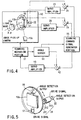
- FIG. 4 shows a structure of a first embodiment of a scanning type image pick-up apparatus according to the present invention. Note that those components of FIG. 4 which are the same as those of FIG. 1 are referred to by the same reference symbols and only those components of FIG. 4 which are different from those of FIG. 1 will now be described in detail below.
- an image pick-up camera 10 is mounted on a scanning mechanism portion 11 and is caused to scan an arbitrary direction decided by synthesizing two-dimensional directions (e.g., the horizontal direction and the vertical direction) by the scanning mechanism portion 11.
- the scanning mechanism portion 11 is equipped with an angle sensor (or angle speed sensor) 14 and a servo amplifier 13 with respect to two axes to be scanned.
- An image pick-up camera is caused to scan arbitrary vertical and horizontal directions by a camera scanning command signal from a scanning command signal generator portion 15 to an adder 12.
- the image pick-up camera 10 introduces light waves passing through a converging lens 10a, to a reflection mirror 10b.
- the reflection mirror 10b is equipped with an angle sensor 18 and a mirror scanning mechanism portion 17 which is caused to perform scanning (i.e., reverse scanning) in a direction opposite to the scanning direction of the image pick-up camera 10.
- the scanning command signal generator portion 15 supplies a signal to the adder 19, thereby to drive the mirror scanning mechanism portion 17.
- the scanning command signal generator portion 15 takes in an angle and an angle speed from the angle sensor 14, to control the angle of reverse scanning and the angle of the axis.
- the reflection mirror 10b is provided with a rotation mechanism 21 around an optical axis and an angle sensor 22, together with the mirror scanning drive portion 17 and the angle sensor 18.
- the rotation mechanism 21 is constructed by rotatably fixing a scanning drive shaft to a ring 211 and by rotating the ring 211 by rotating a motor 213 through a transmission member 212 such as a gear or the like.
- the angle sensor 22 may be equipped on the rotation shaft of the motor 213. In this manner, the reflection mirror 10b is capable of changing the axis of the reverse scanning on the basis of a signal from the scanning command signal generator portion 15, like triangular scanning.
- a command signal for instructing a mirror scanning angle outputted from the scanning command signal generator portion 15 is converted into a drive signal by a servo amplifier 23, and the rotation mechanism 21 is driven on the basis of the drive signal.
- the reverse scanning axis of the reflection mirror 10b is inclined as a result, the inclination angle is detected by an angle sensor 22 and is inputted to a minus input end of an adder 24.
- the adder 24 carries out a subtraction by reducing an output angle of the angle sensor 22 from an angle specified by the mirror scanning command signal inputted to a plus input end of this adder. In this manner, the reverse scanning axis of the reflection mirror 10b is set to an inclination angle corresponding to the command signal.
- ⁇ v is a scanning angle speed in a vertical direction
- ⁇ h is a scanning angle speed in a horizontal direction.
- the image pick-up camera 10 may be replaced with a laser radar.
- a laser beam receiver may be used in place of the image pick-up element 10c.
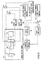
- FIG. 6 shows a structure of a second embodiment of a scanning image pick-up apparatus according to the present invention.
- an image pick-up camera 31 for taking in a light wave is mounted on a scanning mechanism portion 35 and is provided so as to freely scan one axial direction (e.g., an azimuth direction) through the scanning mechanism portion 35.
- a sensor portion 36 is provided on the scanning axis.
- the light waves adopted are those in a visible region (e.g., a range of 0.4 ⁇ m to 0.8 ⁇ m) and an infrared region (e.g., a range of 3 ⁇ m to 12 ⁇ m).
- the above scanning mechanism portion 35 comprises a torquer and a gimbal mechanism and has an input end connected with an output end of an adder 38 through a servo amplifier 37.
- the adder 38 has a plus input end connected with a camera scanning command signal output end of a scanning command signal generator portion 39.
- the adder 38 generates a camera drive signal by obtaining a difference between a camera scanning command signal (e.g., a signal for instructing a scanning angle of the image pick-up camera 31) outputted from the scanning command signal generator portion 39 and an actual scanning angle signal from the sensor portion 36, and outputs the camera drive signal to the scanning mechanism portion 35.
- the scanning mechanism portion 35 controls the scanning angle ⁇ of the image pick-up camera 31 on the basis of a camera drive signal inputted, such that scanning is performed linearly (ref. FIG. 7A).
- the image pick-up camera 31 is constructed by arranging a converging lens 32, an electro-optical deflector 34a, and a charge storage type image pick-up element 33 having a view angle ⁇ on an optical axis. Light waves picked up are converged by the converging lens 32 and the converged light waves are imaged on the image pick-up element 33 through the electro-optical deflector 34a, thereby to obtain a static view image.
- the electro-optical deflector 34a has a structure in which a plurality of prisms made of electro-optical crystal having a so-called electro-optical effect that the refraction factor is changed by applying an electric field are adhered on each other such that optical axes of the prisms are inverted one another.
- a light wave enters into the deflector 34a applied with a uniform electric field the light wave is deflected and injected out.
- the deflection amount can be expressed in form of a function concerning an applied electric field. This means that the deflection amount can be controlled by an applied voltage.
- the angle speed in a scanning direction obtained by the sensor portion 36 is inputted into a deflector control signal generator portion 42, thereby to generates a control signal (or angle command signal) corresponding to a return angle equivalent to an angle movement amount.
- the control signal is converted into a drive voltage by the servo amplifier 40a through the adder 41a and is supplied to the electro-optical deflector 34a.
- a voltage change caused by deflection by the electro-optical deflector 34a is returned and inputted into the adder 41a, thereby to perform deflection corresponding to an angle specified by the control signal.
- the optical deflection angle can be returned in the reverse direction by an angle equivalent to a scanning angle at the frame cycle, as shown in FIG. 7D, when a synchronous trigger corresponding to the frame cycle T is supplied to the deflector control signal generator portion 42 at a timing shown in FIG. 7D. Therefore, the light movement angle on the focus plane of the image pick-up element 33 is constant at the portion of the exposure time Ta, as shown in FIG. 7C, and a static image is thereby obtained, so that a function equivalent to rotation control of a reflection mirror as described before can be realized.
- an angle speed detection output from the sensor portion 36 set on a scanning axis (or rotation axis) is used as a feed back signal to the electro-optical deflector 34a, and therefore, a return angle equivalent to an angle movement amount depending on scanning by the image pick-up camera 31 can be supplied to the electro-optical deflector 34a.
- an image flow caused by scanning can be equivalently restricted and an image during an exposure time can be stopped statically.
- the image pick-up camera 31 may be replaced with a laser radar and a laser beam receiver may be used in place of the image pick-up element in case of applying the present invention to a scanning type laser beam receive apparatus.
- FIG. 8 shows a structure of a third embodiment of a scanning type image pick-up apparatus according to the present invention. Note that those components of FIG. 8 which are the same as those of FIG. 6 are referred to by the same reference symbols and only those portions which are different from those of FIG. 6 will be specifically described below.
- the scanning mechanism portion 35 causes an image pick-up camera 31 to scan two-dimensional directions (which are a horizontal direction and a vertical direction, for example) and a sensor portion 36 detects a scanning angle in each of the directions.
- the image pick-up camera 31 is constructed by arranging a converging lens 32, a first electro-optical deflector 34a, a second electro-optical deflector 34b, and a charge storage type image pick-up element 33 on an optical axis.
- Light waves taken in are converged by the converging lens 32.
- the light waves converged are deflected in a direction opposite to the horizontal scanning direction by the first electro-optical deflector 34a and are deflected in a direction opposite to the vertical scanning direction by the second electro-optical deflector 34b. Thereafter, the light waves are imaged on the image pick-up element 33, thereby to obtain a static view image.
- a deflector control signal generator portion 42 controls the first electro-optical deflector 34a so as to perform deflection in a direction opposite to the horizontal scanning direction at an equal angle speed through an adder 41a and a servo amplifier 40a, and also controls the second electro-optical deflector 34b so as to perform deflection in a direction opposite to the vertical scanning direction through an adder 41b and a servo amplifier 40b.
- the scanning type image pick-up apparatus has an independent electro-optical deflector for each of the horizontal and vertical directions, so that corrections can independently made in both the horizontal and vertical directions. Therefore, an image flow can be restricted independently in both the horizontal and vertical directions by independently feeding back the angle speeds in the horizontal and vertical directions to the electro-optical deflectors 34a and 34b.
- FIG. 9 shows a structure of a fourth embodiment of a scanning type image pick-up apparatus according to the present invention. Note that those components which are the same as those of FIG. 6 are referred to by the same reference symbols and only those components which are different from those of FIG. 6 will be specifically described below.
- a scanning mechanism portion 35 causes an image pick-up camera 31 to scan two-dimensional directions (which are a horizontal direction and a vertical direction, for example) like in the third embodiment, and a sensor portion 36 detects a synthesis scanning angle speed concerning both of the directions.
- the image pick-up camera 31 is constructed by arranging a converging lens 32, an electro-optical deflector 34a, and a charge storage type image pick-up element 33 on an optical axis and by providing a rotation mechanism 44 for rotating the electro-optical deflector 34 around the optical axis.
- Light waves taken in are converged by the converging lens 32 and the light waves thus converged are deflected in a direction opposite to the scanning direction by the electro-optical deflector 34a.
- the light waves are thereafter imaged on the image pick-up element 33, thereby to obtain a static view image.
- a deflector rotation signal generator portion 43 drives the rotation mechanism 44 through the adder 41c and the servo amplifier 40c on the basis of synthesis angle speed data from the sensor portion 36, thereby to cause the deflection direction of the first electro-optical deflector 34b to correspond to the scanning direction, and the deflector control signal generator portion 42 controls the electro-optical deflector 34a so as to perform deflection in a direction opposite to the scanning direction at an equal angle speed through the adder 41a and the servo amplifier 40a.
- the scanning type image pick-up apparatus has an electro-optical deflector 34a which is freely rotatable around an optical axis and the electro-optical deflector 34a is rotated and controlled such that the moving direction of an image corresponds to the deflection direction of light waves.
- the angle speeds in the horizontal and vertical directions are synthesized with each other thereby to obtain the scanning direction and the scanning angle speed of the image pick-up camera 31.
- the signal concerning the scanning direction is fed back to control rotation of the electro-optical deflector 34a around the optical axis and the signal concerning the scanning angle speed is fed back to control the deflection amount of light waves. Therefore, an image flow can be restricted both in the horizontal direction and the vertical direction.
- a scanning type image pick-up apparatus can realize restriction of an image flow without use of a mechanical operating portion.
- the image pick-up camera 31 may be replaced with a laser radar and a laser beam receiver may be used in place of the image pick-up element 10c in case of applying the third or fourth embodiments to a scanning type laser beam receive apparatus.
- a scanning type image pick-up apparatus and a scanning type laser beam receive apparatus which are capable of obtaining a clear view image over a wide view field and realize highly reliable search with high precision.
Landscapes
- Physics & Mathematics (AREA)
- General Physics & Mathematics (AREA)
- Optics & Photonics (AREA)
- Engineering & Computer Science (AREA)
- Multimedia (AREA)
- Signal Processing (AREA)
- Transforming Light Signals Into Electric Signals (AREA)
- Optical Radar Systems And Details Thereof (AREA)
- Facsimile Scanning Arrangements (AREA)
- Studio Devices (AREA)
Claims (17)
- Bildaufnahmevorrichtung vom Abtasttyp, gekennzeichnet durch:eine Bildaufnahmekamera (10), um eine Lichtwelle durch ein erstes optisches System (10a) zu konvergieren, um einen optischen Pfad der Lichtwelle durch ein zweites optisches System (10b) zu ändern und um die Lichtwelle in ein Bildaufnahmeelement von Ladungsspeichertyp (10c) zu nehmen, um dadurch ein Ansichtsbild zu erhalten, wobei das zweite optische System (10b) angeordnet ist, um imstande zu sein, eine Abtastung an dem Bildaufnahmeelement (10c) mit der Lichtwelle von dem ersten optischen System (10a) frei durchzuführen;ein Kameraabtastmittel (11, 12, 13, 14, 15), um die Bildaufnahmekamera (10) zu veranlassen, einen Ansichtsbereich linear abzutasten, um dadurch die Lichtwelle in das erste optische System (10a) zu nehmen;ein optisches Systemabtastmittel (18, 19, 20), um das zweite optische System (10b) der Bildaufnahmekamera (10) zu veranlassen, eine triangulare Abtastung in einer Richtung entgegengesetzt einer Abtastrichtung der Bildaufnahmekamera (10) für jeden Framezyklus der Bildaufnahmekamera (10) durchzuführen, um dadurch die durch das erste optische System (10a) konvergierte Lichtwelle in das Bildaufnahmeelement (10c) einzuführen.
- Bildaufnahmevorrichtung vom Abtasttyp gemäß Anspruch 1, dadurch gekennzeichnet, dass das zweite optische System (10b) bereitgestellt wird, um einer Fokusebene des ersten optischen Systems (10a) zu entsprechen;
- Bildaufnahmevorrichtung vom Abtasttyp gemäß Anspruch 1, dadurch gekennzeichnet, dass das Kameraabtastmittel (11, 12, 13, 14, 15) die Lichtwelle nimmt, indem veranlasst wird, dass die Bildaufnahmekamera (10) zwei axiale Richtungen im Wesentlichen senkrecht zueinander abtastet.
- Bildaufnahmevorrichtung vom Abtasttyp gemäß Anspruch 1, dadurch gekennzeichnet, dass das zweite optische System (10b) der Bildaufnahmekamera (10) durch einen Reflexionsspiegel gebildet wird, um die Lichtwelle zu reflektieren.
- Bildaufnahmevorrichtung vom Abtasttyp gemäß Anspruch 1, dadurch gekennzeichnet, dass das zweite optische System (10b) der Bildaufnahmekamera (10) durch ein optisches Phasenelement gebildet wird, das der Lichtwelle ermöglicht, weiterzulaufen.
- Bildaufnahmevorrichtung vom Abtasttyp gemäß Anspruch 1, dadurch gekennzeichnet, dass:das Kameraabtastmittel (11, 12, 13, 14, 15) ein zweidimensionales Abtastmittel umfasst, um die zweidimensionale Abtastung durchzuführen, indem jede Abtastung in einer senkrechten Richtung zu der Abtastrichtung innerhalb des Ansichtsbereichs verschoben wird;die Bildaufnahmekamera (10) einen Rotationsmechanismus (21, 22, 23, 24) umfasst, um das zweite optische Systems (10b) um eine optische Achse um einen Winkel zu drehen, der durch die Abtastwinkelgeschwindigkeiten in zwei axialen Richtungen des zweidimensionalen Abtastmittels bestimmt wird; unddas optische Systemabtastmittel den Rotationsmechanismus (21, 22, 23, 24) veranlasst, das zweite optische System (10b) um eine Achse parallel zu einer Einfallsoberfläche des Bildaufnahmeelements (10c) mit einer Winkelgeschwindigkeit zu drehen, die durch die Abtastwinkelgeschwindigkeiten in den beiden axialen Richtungen des zweidimensionalen Abtastmittels bestimmt wird.
- Bildaufnahmevorrichtung vom Abtasttyp gemäß Anspruch 1, dadurch gekennzeichnet, dass das zweite optische System (34a - Figuren 6 und 9) ein elektrooptischer Deflektor (34a) ist, um eine optische Achse durch elektrische Steuerung abzulenken.
- Bildaufnahmevorrichtung vom Abtasttyp gemäß Anspruch 1, dadurch gekennzeichnet, dass:das zweite optische System (34a, 34b - Figur 8) erste und zweite elektrooptische Deflektoren (34a, 34b) umfasst, um eine optische Achse in Richtungen senkrecht zueinander durch elektrische Steuerung abzulenken:das Kameraabtastmittel (35, 36, 37, 38, 39 - Figur 8) ein zweidimensionales Abtastmittel umfasst, um eine zweidimensionale Abtastung durchzuführen, indem jede Abtastung in einer Richtung senkrecht zu der Abtastrichtung innerhalb des Ansichtsbereichs verschoben wird;das optische Abtastmittel umfasst: ein erstes Deflektorantriebsmittel (40a, 41b, 42), um den ersten elektrooptischen Deflektor (34a) zu veranlassen, eine optische Achse mit einem Winkel abzulenken, der durch eine Abtastwinkelgeschwindigkeit des zweidimensionalen Abtastmittels (35, 36, 37, 38, 39) in einer ersten axialen Richtung davon bestimmt wird, und ein zweites Deflektorantriebsmittel (40b, 41a, 42), um den zweiten elektrooptischen Deflektor (34b) zu veranlassen, eine optische Achse mit einem Winkel abzulenken, der durch eine Abtastwinkelgeschwindigkeit des zweidimensionalen Abtastmittels (35, 36, 37, 38, 39) in einer zweiten axialen Richtung davon senkrecht zu der ersten axialen Richtung bestimmt wird.
- Laserstrahlaufnahmevorrichtung vom Abtasttyp, gekennzeichnet durch:wobei das optische Systemmittel (17 bis 24) umfasst: einen Rotationsmechanismus, der das zweite optische System (10b) um eine optische Achse um einen Winkel dreht, der durch die Abtastwinkelgeschwindigkeit in zwei axialen Richtungen des zweidimensionalen Abtastmittels (11, 12, 13, 14, 15) bestimmt wird, und um eine Achse parallel zu einer Lichtaufnahmeoberfläche des Laserstrahlempfängers (10c) mit einer Winkelgeschwindigkeit dreht, die durch die Abtastwinkelgeschwindigkeit in den beiden axialen Richtungen des zweidimensionalen Abtastmittels (11, 12, 13, 14, 15) bestimmt wird.einen Laserradar (10), um einen Laserstrahl durch ein erstes optisches System (10a) zu konvergieren, um einen optischen Pfad des Laserstrahls durch ein zweites optisches System (10b) zu ändern und um den Laserstrahl in einen Laserstrahlempfänger (10c) zu nehmen, um dadurch ein Ansichtsbild zu erhalten, wobei das zweite optische System (10b) angeordnet ist, um imstande zu sein, die Abtastung frei durchzuführen, um dem ersten optischen System (10a) und dem Laserstrahlempfänger (10c) zu entsprechen;ein zweidimensionales Abtastmittel (11, 12, 13, 14, 15), um den Laserradar (10) zu veranlassen, einen Ansichtsbereich linear abzutasten, um dadurch den Laserstrahl in das erste optische System (10a) zu nehmen, undein optisches Systemsteuermittel (17 bis 24), um die triangulare Abtastung des zweiten optischen Systems (10b) des Laserradars (10) in einer Richtung entgegengesetzt zu einer Abtastrichtung des Laserradars (10) für jeden Framezyklus des Laserstrahlempfängers (10c) durchzuführen, um dadurch den durch das erste optische System (10a) konvergierten Laserstrahl in den Laserstrahlempfänger (10c) einzuführen;
- Laserstrahlempfangsvorrichtung vom Abtasttyp gemäß Anspruch 9, dadurch gekennzeichnet, dass das zweite optische System (10b) bereitgestellt wird, um einer Fokusebene des ersten optischen Systems (10a) zu entsprechen.
- Laserstrahlempfangsvorrichtung vom Abtasttyp gemäß Anspruch 9, dadurch gekennzeichnet, dass das zweidimensionale Abtastmittel (11, 12, 13, 14, 15) den Laserstrahl aufnimmt, in dem der Laserradar (10) veranlasst wird, zwei axiale Richtungen im Wesentlichen senkrecht zueinander abzutasten.
- Laserstrahlempfangsvorrichtung vom Abtasttyp gemäß Anspruch 9, dadurch gekennzeichnet, dass das zweite optische System (10b) des Laserradars (10) durch einen Reflexionsspiegel gebildet wird, um den Laserstrahl zu reflektieren.
- Laserstrahlempfangsvorrichtung vom Abtasttyp gemäß Anspruch 9, dadurch gekennzeichnet, dass das zweite optische System (10b) des Laserstrahls (10) durch ein optisches Phasenelement gebildet wird, das dem Laserstrahl ermöglicht, weiterzulaufen.
- Laserstrahlempfangsvorrichtung vom Abtasttyp, gekennzeichnet durch:einen Laserradar (31), um einen Laserstrahl durch ein erstes optisches System (32) zu konvergieren, um einen optischen Pfad des Laserstrahls durch ein zweites optisches System (34a) zu ändern und um den Laserstrahl in einen Laserstrahlempfänger (33) zu nehmen, um dadurch ein Ansichtsbild zu erhalten, wobei das zweite optische System (34a) angeordnet ist, um imstande zu sein, die Abtastung mittels eines elektrooptischen Deflektors (34a) frei durchzuführen, der imstande ist, den Laserstrahl elektrisch abzulenken, um dem ersten optischen System (32) und dem Laserstrahlempfänger (33) zu entsprechen;ein Abtastmittel (35, 36, 37, 38, 39), um den Laserradar (31) zu veranlassen, einen Ansichtsbereich linear abzutasten, um dadurch den Laserstrahl in das erste optische System (32) zu nehmen;ein Deflektorantriebsmittel (40a, 41a, 42), um den elektrooptischen Deflektor (34a) zu veranlassen, eine optische Achse mit einem Winkel abzulenken, der durch eine Abtastwinkelgeschwindigkeit des Abtastmittels (35, 36, 37, 38, 39) bestimmt wird, und um eine triangulare Abtastung in einer Richtung entgegengesetzt zu einer Abtastrichtung des Laserradars (31) für jeden Framezyklus des Laserstrahlempfängers (33) durchzuführen, um dadurch den durch das erste optische System (32) konvergierten Laserstrahl in den Laserstrahlempfänger (33) einzuführen.
- Laserstrahlempfangsvorrichtung vom Abtasttyp gemäß Anspruch 14, dadurch gekennzeichnet, dass:wobei das optische Abtastmittel umfasst: ein erstes Deflektorantriebsmittel (40a, 41b, 42), um den ersten elektrooptischen Deflektor (34a) zu veranlassen, eine optische Achse mit einem Winkel abzulenken, der durch die Abtastwinkelgeschwindigkeit des zweidimensionalen Abtastmittels (35, 36, 37, 38, 39) in einer ersten axialen Richtung davon bestimmt wird, und ein zweites Deflektorantriebsmittel (40b, 41a, 42), um den zweiten elektrooptischen Deflektor (34b) zu veranlassen, eine optische Achse mit einem Winkel abzulenken, der durch die Abtastwinkelgeschwindigkeit des zweidimensionalen Abtastmittels (35, 36, 37, 38, 39) in einer zweiten axialen Richtung davon senkrecht zu der ersten axialen Richtung bestimmt wird.das zweite optische System (34a, 34b) erste und zweite elektrooptische Deflektoren (34a, 34b) umfasst, um eine optische Achse in Richtungen senkrecht zueinander durch elektrische Steuerung abzulenken;das Abtastmittel (35, 36, 37, 38, 39) ein zweidimensionales Abtastmittel umfasst, um die zweidimensionale Abtastung durchzuführen, indem jede Abtastung in einer Richtung senkrecht zu der Abtastrichtung innerhalb des Ansichtsbereichs verschoben wird;
- Laserstrahlempfangsvorrichtung vom Abtasttyp gemäß einem der Ansprüche 14 bis 15, dadurch gekennzeichnet, dass das zweite optische System (34a) bereitgestellt wird, um einer Fokusebene des ersten optischen Systems (32) zu entsprechen.
- Laserstrahlempfangsvorrichtung vom Abtasttyp gemäß Anspruch 15, dadurch gekennzeichnet, dass das zweidimensionale Abtastmittel (35, 36, 37, 38, 39) den Laserstrahl einnimmt, indem der Laserstrahl (31) veranlasst wird, zwei axiale Richtungen im Wesentlichen senkrecht zueinander abzutasten.
Applications Claiming Priority (6)
| Application Number | Priority Date | Filing Date | Title |
|---|---|---|---|
| JP307569/96 | 1996-11-19 | ||
| JP30756996 | 1996-11-19 | ||
| JP30756996 | 1996-11-19 | ||
| JP16584097A JP3410929B2 (ja) | 1996-11-19 | 1997-06-23 | 走査型撮像装置と走査型レーザ受光装置 |
| JP16584097 | 1997-06-23 | ||
| JP165840/97 | 1997-06-23 |
Publications (3)
| Publication Number | Publication Date |
|---|---|
| EP0843183A2 EP0843183A2 (de) | 1998-05-20 |
| EP0843183A3 EP0843183A3 (de) | 1999-11-17 |
| EP0843183B1 true EP0843183B1 (de) | 2005-03-30 |
Family
ID=26490422
Family Applications (1)
| Application Number | Title | Priority Date | Filing Date |
|---|---|---|---|
| EP97309313A Expired - Lifetime EP0843183B1 (de) | 1996-11-19 | 1997-11-18 | Abtastbildaufnahmegerät und ein Abtastlaserempfänger |
Country Status (6)
| Country | Link |
|---|---|
| US (3) | US6449012B1 (de) |
| EP (1) | EP0843183B1 (de) |
| JP (1) | JP3410929B2 (de) |
| KR (1) | KR100255028B1 (de) |
| CA (1) | CA2221063C (de) |
| DE (1) | DE69732888T2 (de) |
Families Citing this family (16)
| Publication number | Priority date | Publication date | Assignee | Title |
|---|---|---|---|---|
| JP3410929B2 (ja) * | 1996-11-19 | 2003-05-26 | 株式会社東芝 | 走査型撮像装置と走査型レーザ受光装置 |
| JP2001128038A (ja) * | 1999-10-27 | 2001-05-11 | Canon Inc | 撮像ユニットおよびこれを備えた装置、テレビ電話、携帯端末、コンピュータ、車載カメラ、監視カメラ、内視鏡 |
| GB2368992B (en) * | 2000-11-10 | 2005-03-30 | Nokia Mobile Phones Ltd | Mobile Imaging |
| US6987566B1 (en) * | 2002-11-27 | 2006-01-17 | Itt Manufacturing Enterprises, Inc. | Methods and apparatus for analyzing mirror reflectance |
| JP4407663B2 (ja) * | 2005-10-13 | 2010-02-03 | 株式会社デンソーウェーブ | 撮像装置 |
| JP4462212B2 (ja) * | 2006-03-14 | 2010-05-12 | パナソニック株式会社 | センサの回転制御方法及び障害物回避方法 |
| US8072482B2 (en) | 2006-11-09 | 2011-12-06 | Innovative Signal Anlysis | Imaging system having a rotatable image-directing device |
| JP4653123B2 (ja) * | 2007-01-09 | 2011-03-16 | 富士フイルム株式会社 | 画像取得装置および画像取得方法 |
| KR20080110341A (ko) * | 2007-06-15 | 2008-12-18 | 삼성전자주식회사 | 마이크로 스캐너 및 이를 이용한 영상투사장치 |
| US8396685B2 (en) | 2009-09-15 | 2013-03-12 | Qualcomm Incorporated | Small form-factor distance sensor |
| CN102055901B (zh) * | 2009-11-05 | 2014-01-22 | 鸿富锦精密工业(深圳)有限公司 | Ptz摄影机及其ptz控制方法 |
| US9430923B2 (en) | 2009-11-30 | 2016-08-30 | Innovative Signal Analysis, Inc. | Moving object detection, tracking, and displaying systems |
| US20120069238A1 (en) * | 2010-09-16 | 2012-03-22 | Panasonic Corporation | Image capturing device |
| US10139819B2 (en) | 2014-08-22 | 2018-11-27 | Innovative Signal Analysis, Inc. | Video enabled inspection using unmanned aerial vehicles |
| JP6439068B1 (ja) | 2018-03-29 | 2018-12-19 | 株式会社日立製作所 | 移動体撮像装置、及び、移動体撮像方法 |
| JP7195986B2 (ja) * | 2019-03-20 | 2022-12-26 | 株式会社東芝 | 走査型撮像装置 |
Family Cites Families (20)
| Publication number | Priority date | Publication date | Assignee | Title |
|---|---|---|---|---|
| US4347530A (en) | 1980-10-24 | 1982-08-31 | Inframetrics, Inc. | Scanning mirror arrangement |
| JPS57142603A (en) * | 1981-02-27 | 1982-09-03 | Canon Inc | Optical scanner |
| GB2144291A (en) | 1983-07-15 | 1985-02-27 | Marconi Avionics | Electro-optic imager vibration compensation |
| US5049740A (en) | 1984-12-26 | 1991-09-17 | Hughes Aircraft Company | Multiple field of view sensor |
| US4712142A (en) * | 1985-08-27 | 1987-12-08 | Mitsubishi Denki Kabushiki Kaisha | Image pickup apparatus with range specification of displayed image |
| JP2681521B2 (ja) * | 1989-10-16 | 1997-11-26 | コニカ株式会社 | カメラ |
| JP2779053B2 (ja) * | 1990-09-25 | 1998-07-23 | 株式会社日立製作所 | 光走査装置 |
| JPH06350931A (ja) * | 1993-06-02 | 1994-12-22 | Hamamatsu Photonics Kk | 固体撮像装置 |
| US6018363A (en) * | 1994-04-28 | 2000-01-25 | Canon Kabushiki Kaisha | Image sensing apparatus with optical-axis deflecting device |
| JP3332130B2 (ja) * | 1994-05-16 | 2002-10-07 | シャープ株式会社 | 画像表示装置 |
| US5877806A (en) * | 1994-10-31 | 1999-03-02 | Ohtsuka Patent Office | Image sensing apparatus for obtaining high resolution computer video signals by performing pixel displacement using optical path deflection |
| JP3190220B2 (ja) * | 1994-12-20 | 2001-07-23 | シャープ株式会社 | 撮像装置 |
| JP3432949B2 (ja) | 1995-05-02 | 2003-08-04 | 株式会社東芝 | 光波捜索装置 |
| JPH08317293A (ja) * | 1995-05-17 | 1996-11-29 | Minolta Co Ltd | 撮像装置 |
| JPH0974524A (ja) * | 1995-07-05 | 1997-03-18 | Sharp Corp | 画像入力装置 |
| JPH09247553A (ja) * | 1996-03-01 | 1997-09-19 | Minolta Co Ltd | ラインセンサカメラ |
| US6233014B1 (en) * | 1996-04-17 | 2001-05-15 | Minolta Co., Ltd. | Line sensor camera without distortion in photo image |
| US6181378B1 (en) * | 1996-06-14 | 2001-01-30 | Asahi Kogaku Kogyo Kabushiki Kaisha | Image reading device |
| JP3410929B2 (ja) * | 1996-11-19 | 2003-05-26 | 株式会社東芝 | 走査型撮像装置と走査型レーザ受光装置 |
| US6163346A (en) * | 1997-09-29 | 2000-12-19 | Zilog, Incorporated | Dot crawl reduction in NTSC/PAL graphic encoder |
-
1997
- 1997-06-23 JP JP16584097A patent/JP3410929B2/ja not_active Expired - Fee Related
- 1997-11-14 CA CA002221063A patent/CA2221063C/en not_active Expired - Fee Related
- 1997-11-17 US US08/972,015 patent/US6449012B1/en not_active Expired - Fee Related
- 1997-11-18 DE DE69732888T patent/DE69732888T2/de not_active Expired - Lifetime
- 1997-11-18 EP EP97309313A patent/EP0843183B1/de not_active Expired - Lifetime
- 1997-11-19 KR KR1019970061069A patent/KR100255028B1/ko not_active Expired - Fee Related
-
2002
- 2002-07-12 US US10/193,177 patent/US7489330B2/en not_active Expired - Fee Related
- 2002-07-15 US US10/193,917 patent/US7289153B2/en not_active Expired - Fee Related
Also Published As
| Publication number | Publication date |
|---|---|
| US6449012B1 (en) | 2002-09-10 |
| JPH10210246A (ja) | 1998-08-07 |
| EP0843183A2 (de) | 1998-05-20 |
| KR19980042586A (ko) | 1998-08-17 |
| DE69732888D1 (de) | 2005-05-04 |
| US20020191092A1 (en) | 2002-12-19 |
| JP3410929B2 (ja) | 2003-05-26 |
| US20020176017A1 (en) | 2002-11-28 |
| CA2221063C (en) | 2000-05-02 |
| KR100255028B1 (ko) | 2000-05-01 |
| DE69732888T2 (de) | 2006-04-06 |
| US7489330B2 (en) | 2009-02-10 |
| US7289153B2 (en) | 2007-10-30 |
| EP0843183A3 (de) | 1999-11-17 |
Similar Documents
| Publication | Publication Date | Title |
|---|---|---|
| EP0843183B1 (de) | Abtastbildaufnahmegerät und ein Abtastlaserempfänger | |
| US5663825A (en) | Stabilized step/stare scanning device | |
| US4923263A (en) | Rotating mirror optical scanning device | |
| US5796511A (en) | Multi-beam scanner with acousto-optic element for scanning imaging surfaces | |
| EP0050970B1 (de) | Optisch-mechanischer Abtastmechanismus | |
| KR19980071039A (ko) | 광학현미경장치 | |
| US5107117A (en) | Optoelectronic viewing system | |
| CN107819993A (zh) | 一种采用光电探测器阵列实现大范围扫描成像的装置及方法 | |
| US5339188A (en) | Step stare scanning apparatus and method | |
| US5877494A (en) | Beam error correction using movable correction element | |
| JP2772777B2 (ja) | 太陽追尾装置 | |
| US5986810A (en) | Imaging system | |
| JP3662625B2 (ja) | イメージング・システム | |
| CN1142678C (zh) | 具有级联扫描光学系统的扫描设备 | |
| US5239404A (en) | Large angle reflective scanning system and method | |
| US5864418A (en) | Multi-beam scanner with mechanically moving element for scanning imaging surfaces | |
| EP1234195A1 (de) | Echtzeit millimeterwellenabtastbildformer | |
| US4945287A (en) | Multiple pentaprism scanning device and method | |
| JP2003315710A (ja) | マルチビーム走査装置及び画像形成装置 | |
| JP3432949B2 (ja) | 光波捜索装置 | |
| JPH09197579A (ja) | 立体視撮像望遠鏡 | |
| GB2279762A (en) | Optical scanning system | |
| JPH0248884B2 (de) | ||
| JPH04165596A (ja) | 光空間伝送装置 |
Legal Events
| Date | Code | Title | Description |
|---|---|---|---|
| PUAI | Public reference made under article 153(3) epc to a published international application that has entered the european phase |
Free format text: ORIGINAL CODE: 0009012 |
|
| 17P | Request for examination filed |
Effective date: 19971217 |
|
| AK | Designated contracting states |
Kind code of ref document: A2 Designated state(s): DE FR GB IT NL |
|
| AX | Request for extension of the european patent |
Free format text: AL;LT;LV;MK;RO;SI |
|
| PUAL | Search report despatched |
Free format text: ORIGINAL CODE: 0009013 |
|
| AK | Designated contracting states |
Kind code of ref document: A3 Designated state(s): AT BE CH DE DK ES FI FR GB GR IE IT LI LU MC NL PT SE |
|
| AX | Request for extension of the european patent |
Free format text: AL;LT;LV;MK;RO;SI |
|
| RIC1 | Information provided on ipc code assigned before grant |
Free format text: 6G 01S 17/93 A, 6G 01S 7/481 B, 6H 04N 3/08 B |
|
| AKX | Designation fees paid |
Free format text: DE FR GB IT NL |
|
| 17Q | First examination report despatched |
Effective date: 20030723 |
|
| GRAP | Despatch of communication of intention to grant a patent |
Free format text: ORIGINAL CODE: EPIDOSNIGR1 |
|
| GRAS | Grant fee paid |
Free format text: ORIGINAL CODE: EPIDOSNIGR3 |
|
| GRAA | (expected) grant |
Free format text: ORIGINAL CODE: 0009210 |
|
| AK | Designated contracting states |
Kind code of ref document: B1 Designated state(s): DE FR GB IT NL |
|
| PG25 | Lapsed in a contracting state [announced via postgrant information from national office to epo] |
Ref country code: NL Free format text: LAPSE BECAUSE OF FAILURE TO SUBMIT A TRANSLATION OF THE DESCRIPTION OR TO PAY THE FEE WITHIN THE PRESCRIBED TIME-LIMIT Effective date: 20050330 Ref country code: IT Free format text: LAPSE BECAUSE OF FAILURE TO SUBMIT A TRANSLATION OF THE DESCRIPTION OR TO PAY THE FEE WITHIN THE PRE;WARNING: LAPSES OF ITALIAN PATENTS WITH EFFECTIVE DATE BEFORE 2007 MAY HAVE OCCURRED AT ANY TIME BEFORE 2007. THE CORRECT EFFECTIVE DATE MAY BE DIFFERENT FROM THE ONE RECORDED.SCRIBED TIME-LIMIT Effective date: 20050330 |
|
| REG | Reference to a national code |
Ref country code: GB Ref legal event code: FG4D |
|
| REF | Corresponds to: |
Ref document number: 69732888 Country of ref document: DE Date of ref document: 20050504 Kind code of ref document: P |
|
| NLV1 | Nl: lapsed or annulled due to failure to fulfill the requirements of art. 29p and 29m of the patents act | ||
| PLBE | No opposition filed within time limit |
Free format text: ORIGINAL CODE: 0009261 |
|
| ET | Fr: translation filed | ||
| 26N | No opposition filed |
Effective date: 20060102 |
|
| REG | Reference to a national code |
Ref country code: GB Ref legal event code: 746 Effective date: 20090517 |
|
| PGFP | Annual fee paid to national office [announced via postgrant information from national office to epo] |
Ref country code: DE Payment date: 20091112 Year of fee payment: 13 |
|
| PGFP | Annual fee paid to national office [announced via postgrant information from national office to epo] |
Ref country code: GB Payment date: 20091118 Year of fee payment: 13 Ref country code: FR Payment date: 20091123 Year of fee payment: 13 |
|
| GBPC | Gb: european patent ceased through non-payment of renewal fee |
Effective date: 20101118 |
|
| REG | Reference to a national code |
Ref country code: FR Ref legal event code: ST Effective date: 20110801 |
|
| REG | Reference to a national code |
Ref country code: DE Ref legal event code: R119 Ref document number: 69732888 Country of ref document: DE Effective date: 20110601 Ref country code: DE Ref legal event code: R119 Ref document number: 69732888 Country of ref document: DE Effective date: 20110531 |
|
| PG25 | Lapsed in a contracting state [announced via postgrant information from national office to epo] |
Ref country code: DE Free format text: LAPSE BECAUSE OF NON-PAYMENT OF DUE FEES Effective date: 20110531 |
|
| PG25 | Lapsed in a contracting state [announced via postgrant information from national office to epo] |
Ref country code: FR Free format text: LAPSE BECAUSE OF NON-PAYMENT OF DUE FEES Effective date: 20101130 |
|
| PG25 | Lapsed in a contracting state [announced via postgrant information from national office to epo] |
Ref country code: GB Free format text: LAPSE BECAUSE OF NON-PAYMENT OF DUE FEES Effective date: 20101118 |