EP0843513A1 - Bearbeitungsbetriebsmethode - Google Patents
Bearbeitungsbetriebsmethode Download PDFInfo
- Publication number
- EP0843513A1 EP0843513A1 EP97924361A EP97924361A EP0843513A1 EP 0843513 A1 EP0843513 A1 EP 0843513A1 EP 97924361 A EP97924361 A EP 97924361A EP 97924361 A EP97924361 A EP 97924361A EP 0843513 A1 EP0843513 A1 EP 0843513A1
- Authority
- EP
- European Patent Office
- Prior art keywords
- equipment
- tact time
- machines
- mounting
- groups
- Prior art date
- Legal status (The legal status is an assumption and is not a legal conclusion. Google has not performed a legal analysis and makes no representation as to the accuracy of the status listed.)
- Granted
Links
Images




Classifications
-
- H—ELECTRICITY
- H05—ELECTRIC TECHNIQUES NOT OTHERWISE PROVIDED FOR
- H05K—PRINTED CIRCUITS; CASINGS OR CONSTRUCTIONAL DETAILS OF ELECTRIC APPARATUS; MANUFACTURE OF ASSEMBLAGES OF ELECTRICAL COMPONENTS
- H05K13/00—Apparatus or processes specially adapted for manufacturing or adjusting assemblages of electric components
- H05K13/08—Monitoring manufacture of assemblages
- H05K13/085—Production planning, e.g. of allocation of products to machines, of mounting sequences at machine or facility level
-
- Y—GENERAL TAGGING OF NEW TECHNOLOGICAL DEVELOPMENTS; GENERAL TAGGING OF CROSS-SECTIONAL TECHNOLOGIES SPANNING OVER SEVERAL SECTIONS OF THE IPC; TECHNICAL SUBJECTS COVERED BY FORMER USPC CROSS-REFERENCE ART COLLECTIONS [XRACs] AND DIGESTS
- Y02—TECHNOLOGIES OR APPLICATIONS FOR MITIGATION OR ADAPTATION AGAINST CLIMATE CHANGE
- Y02P—CLIMATE CHANGE MITIGATION TECHNOLOGIES IN THE PRODUCTION OR PROCESSING OF GOODS
- Y02P90/00—Enabling technologies with a potential contribution to greenhouse gas [GHG] emissions mitigation
- Y02P90/02—Total factory control, e.g. smart factories, flexible manufacturing systems [FMS] or integrated manufacturing systems [IMS]
-
- Y—GENERAL TAGGING OF NEW TECHNOLOGICAL DEVELOPMENTS; GENERAL TAGGING OF CROSS-SECTIONAL TECHNOLOGIES SPANNING OVER SEVERAL SECTIONS OF THE IPC; TECHNICAL SUBJECTS COVERED BY FORMER USPC CROSS-REFERENCE ART COLLECTIONS [XRACs] AND DIGESTS
- Y10—TECHNICAL SUBJECTS COVERED BY FORMER USPC
- Y10T—TECHNICAL SUBJECTS COVERED BY FORMER US CLASSIFICATION
- Y10T29/00—Metal working
- Y10T29/49—Method of mechanical manufacture
- Y10T29/49002—Electrical device making
- Y10T29/49117—Conductor or circuit manufacturing
- Y10T29/49124—On flat or curved insulated base, e.g., printed circuit, etc.
- Y10T29/4913—Assembling to base an electrical component, e.g., capacitor, etc.
-
- Y—GENERAL TAGGING OF NEW TECHNOLOGICAL DEVELOPMENTS; GENERAL TAGGING OF CROSS-SECTIONAL TECHNOLOGIES SPANNING OVER SEVERAL SECTIONS OF THE IPC; TECHNICAL SUBJECTS COVERED BY FORMER USPC CROSS-REFERENCE ART COLLECTIONS [XRACs] AND DIGESTS
- Y10—TECHNICAL SUBJECTS COVERED BY FORMER USPC
- Y10T—TECHNICAL SUBJECTS COVERED BY FORMER US CLASSIFICATION
- Y10T29/00—Metal working
- Y10T29/51—Plural diverse manufacturing apparatus including means for metal shaping or assembling
- Y10T29/5136—Separate tool stations for selective or successive operation on work
- Y10T29/5137—Separate tool stations for selective or successive operation on work including assembling or disassembling station
-
- Y—GENERAL TAGGING OF NEW TECHNOLOGICAL DEVELOPMENTS; GENERAL TAGGING OF CROSS-SECTIONAL TECHNOLOGIES SPANNING OVER SEVERAL SECTIONS OF THE IPC; TECHNICAL SUBJECTS COVERED BY FORMER USPC CROSS-REFERENCE ART COLLECTIONS [XRACs] AND DIGESTS
- Y10—TECHNICAL SUBJECTS COVERED BY FORMER USPC
- Y10T—TECHNICAL SUBJECTS COVERED BY FORMER US CLASSIFICATION
- Y10T29/00—Metal working
- Y10T29/53—Means to assemble or disassemble
- Y10T29/5313—Means to assemble electrical device
- Y10T29/53174—Means to fasten electrical component to wiring board, base, or substrate
- Y10T29/53178—Chip component
Definitions
- the present invention relates to an operation method of equipment, through which an appropriate composition of an assembling line is found from plural groups of mounting equipment which mount electronic parts onto a PCB (printed circuit board), and more particularly by selecting machines for manufacturing a specific PCB (printed circuit board) so that a tact time (tact time: maximum work time necessary for a process) of the assembly line may not exceed the initial set tact time.
- a tact time tact time: maximum work time necessary for a process
- an assembly line has been composed by utilizing individual feature of each mounting machine, and thereby manufacturing a PCB.
- a high-speed surface mounting machine mounts the parts, and when mounting QFP (quad flat package) and others having so narrow spacing between pathways of leads or pins that a precise mounting is required, a robot type machine featuring precise mounting is employed after the process using the high-speed machine.
- QFP quad flat package
- Such an operation of combining different types of machines improves a quality and an efficiency of the entire assembly line.
- It is also a well-known operation method that a plurality of the same machines is placed in one assembly line in order to shorten a tact time of the assembly line.
- the present invention provides an operation method of equipment which determines a line composition by selecting appropriate machines from groups of equipment for processing designated products so that a tact time of an assembly line may not exceed the initial set tact time.
- the operation comprises the following three processes:
- a line composition of which tact time is not more than an initial set tact time can be automatically determined through selecting necessary machines from the equipment for processing a designated product.
- Fig. 1 is a hardware partial view used in the operation method of equipment of the present invention.
- Fig. 2 depicts a structuring method of control information used in an embodiment of the present invention.
- Fig. 3 depicts data tables flow of the control information used in an embodiment of the present invention.
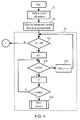
- Fig. 4 is an information flow chart of determining a line composition used in an embodiment of the present invention.
- Fig. 5 is another information flow chart for determining a line composition used in an embodiment of the present invention.
- Fig. 6 is further information flow chart for determining a line composition used in an embodiment of the present invention.
- Fig. 7 is still further information flow chart for determining a line composition used in an embodiment of the present invention.
- the invention disclosed in Claim 1 provides an equipment operation method which has plural groups of equipment for mounting parts onto an object to be processed, and which determines a line composition by selecting appropriate machines from the groups of equipment for processing designated products so that a tact time of an assembly line may not exceed an initial set tact time.
- the operation comprises the following three processes:
- the invention disclosed in Claim 1 can automatically determine a line composition of which tact time is not more than an initial set time by selecting necessary machines from the groups of equipment.
- the invention disclosed in Claim 2 proves an equipment operation method which determines a line composition, in plural groups of mounting equipment which mount electronic parts onto PCBs, by selecting appropriate mounting machines from the groups of mounting equipment for mounting electronic parts to designated PCBs so that a tact time of an assembly line may not exceed an initial set tact time.
- the operation comprises the following three processes:
- the invention disclosed in Claim 2 can automatically determine a line composition of which tact time is not more than an initial set time by selecting necessary mounting machines from the groups of mounting equipment.
- Fig. 1 shows hardware partial view used in the equipment operation method of the present invention, where a CPU 3 (Central Processing Unit) executes input/output about control information 2 stored in an external storage 1.
- the external storage 1 may be composed of a relational data base system or a file system which is known as a public domain.
- An equipment operation method of the present invention comprises Process 1, Process 2 and Process 3 detailed below:
- a method structuring control information is explained based on Fig. 2.
- Electronic parts 4 are mounted on a PCB 5 by various types of mounting machines 8.
- Parts are assigned to available machines (Part Assignment 12), which can mount or which should prioritize based on machines features, in accordance with shapes and characteristics of parts.
- An assignment table 6 contains information about parts to be mounted on a PCB.
- a partial-assignment-table 7 is a subset of the assignment table 6.
- the plural groups of equipment are grouped based on equipment's features and a line composition is determined in Process 2 and onward.
- Groups of mounting equipment 9 are grouped into an equipment GROUP 10, an equipment TYPE 11 (each machine is included in the equipment group 10), and a mounting machine 8 (each mounting machine is included in the equipment type 11.)
- the equipment GROUP When there are different conditions of mounting methods, the equipment GROUP is used to compose a line based on a same mounting method.
- There may be several equipment GROUPS such as a surface mounting group, insertion machine group, and semiconductor mounting group. The priority order of part assignment is applied between the groups.
- the equipment TYPE is used when there are different features within a same equipment GROUP. There may be several types such as high-speed mounting machine, and multifunctional mounting machine. The priority order of part assignment is applied between the types and also between each machine.
- control information 2 including the grouping mentioned above is detailed by referring to Fig. 3.
- the control information 2 is grouped depending on relevant information, and the control information 2 is managed every table. Each table can refer to others by using a relevant item as a key.
- the attributes of a specific PCB are controlled with the assignment table numbers (cad_id) of the assignment table 21.
- the part assignment number(sub_id) on the part assignment table identifies the parts thereon, a part number(part_id) thereof identifies an electronic part thereon, a number of an electronic part(part-num) is a quantity of the part to be mounted onto the PCB.
- a machine number(mc_id) identifies a machine to which the parts are assigned.
- a part mounting tact(tact) is a tact time for mounting a part onto the PCB by the machine. The machine number and the part mounting tact time are set as computing results of the CPU. When a specific part must be assigned to a specific machine beforehand, a machine number can be assigned before a computing operation.
- the part attribute 22 is linked with the assignment table 21 through the part number(part-id) to set the attribute of electronic parts.
- a part shape number(shape-id) is used for specifying a part shape.
- Other data such as a size of a part, or species of parts including QFP (quad flat package) and SOP (small outline package) can be used for the part number.
- the equipment operation 24 sets the part tact time of the part corresponding to the part shape number(master-id), which part is mounted onto the PCB by the equipment specified with the species number.
- the equipment master 23 controls every aspect of the equipment.
- the species number(master-id) identifies a species of equipment, a type number groups features of equipment, a part loadable number(max parts) is a maximum loadable quantity of parts to a machine, and a loading tact time is a travel time for transferring a PCB.
- a tool change tact(change-tact) sets a time to be spent for changing chucks or nozzles transferring parts before mounting. This tool change tact time is used in general type machines such as a robot type. Other tact times proper to the machine can be supplemented to this table.
- User's equipment 25 is to control the equipment which a user keeps in his factory.
- a machine number (mc_id) identifies a machine, and a species number(master-id) is linked to the species number of equipment controlled by the equipment master 23.
- the priority order of part assignment (priority) is applied to when assigning the same type of machines within a same line.
- the equipment TYPE 26 controls the priority order of type numbers (master_type) on the equipment master 23.
- the type numbers of equipment are linked with the type numbers listed on the equipment master 23.
- An assignment priority order is a priority order of the equipment types.
- the equipment group number (group_id) is used when one type of PCB needs different lines.
- Equipment GROUP 27 controls the equipment group of the equipment TYPE.
- the equipment group numbers are linked with the equipment group numbers of the equipment TYPE.
- An assignment priority order is a priority order of the equipment group.
- a computing operation result is written into the line composition 28.
- a line number(line_id) specifies the computing operation result, and a machine number is proper to machines composing a line. The machine number is linked with the machine number in the users equipment 25.
- a machine tact (mc_tact) is a tact time of each machine comprising the line.
- a composition order (order) is an order of machines comprising the line.
- Fig. 4 depicts this process: write the control information of Process 1 (S1), and select a part assignment table No. corresponding to a PCB in order to identity the PCB (S2). Then assign the parts to each equipment group (S3).
- Fig. 5 depicts this process: take out any single part from the part assignment table AR(n), and assign the part to loadable machines of equipment TYPE (m) which belongs to a proper equipment GROUP (n), then supplement the machines assigned with the part to a partial line L (m) proper to the equipment TYPE (S4).
- Process 3 is detailed by referring to Fig. 7. Integrate the partial lines set up type-wise in Process 2 into one of a line of the equipment GROUP G(n) (S6). Then, smooth out the line (S7) so that differences between tact times may be minimized.
- the total tact time of each machine is a sum of a loading tact time listed on the equipment master 23, tool change tact time, and part mounting tact time listed on the equipment operation 24 ⁇ quantity.
- the tact time of a line is the longest tact time of the machines.
- a line composition of which tact time is less than the initial set tact time can be automatically determined.
- the present invention can save a lot of time and labor which a conventional method by manual work requires.
- a common line composition is needed for plural types of PCBs.
- the present invention can repeat calculations automatically for every type of PCBs until the tact times of all types of PCBs are satisfied.
- the present invention enable any staff in the factory to find a line composition through inputting control information. Therefore, it is not any more necessary to rely on a skilled person about the mounting conditions of equipment for determining the line composition.
- each station completes an assigned task within an allotted time.
- the allotted time is different with each other depending on task content and station's capacity.
- the maximum allotted time for the stations is called as a tact time, which limits a conveyer speed or a line speed.
Landscapes
- Engineering & Computer Science (AREA)
- Operations Research (AREA)
- Manufacturing & Machinery (AREA)
- Microelectronics & Electronic Packaging (AREA)
- General Factory Administration (AREA)
- Supply And Installment Of Electrical Components (AREA)
- Management, Administration, Business Operations System, And Electronic Commerce (AREA)
- Multi-Process Working Machines And Systems (AREA)
Applications Claiming Priority (4)
| Application Number | Priority Date | Filing Date | Title |
|---|---|---|---|
| JP14390196A JP3537267B2 (ja) | 1996-06-06 | 1996-06-06 | 設備運用方法 |
| JP143901/96 | 1996-06-06 | ||
| JP14390196 | 1996-06-06 | ||
| PCT/JP1997/001970 WO1997047170A1 (en) | 1996-06-06 | 1997-06-06 | Facility operating method |
Publications (3)
| Publication Number | Publication Date |
|---|---|
| EP0843513A1 true EP0843513A1 (de) | 1998-05-20 |
| EP0843513A4 EP0843513A4 (de) | 2000-12-06 |
| EP0843513B1 EP0843513B1 (de) | 2004-05-12 |
Family
ID=15349708
Family Applications (1)
| Application Number | Title | Priority Date | Filing Date |
|---|---|---|---|
| EP97924361A Expired - Lifetime EP0843513B1 (de) | 1996-06-06 | 1997-06-06 | Bearbeitungsbetriebsmethode |
Country Status (5)
| Country | Link |
|---|---|
| US (1) | US5980086A (de) |
| EP (1) | EP0843513B1 (de) |
| JP (1) | JP3537267B2 (de) |
| DE (1) | DE69729051T2 (de) |
| WO (1) | WO1997047170A1 (de) |
Families Citing this family (11)
| Publication number | Priority date | Publication date | Assignee | Title |
|---|---|---|---|---|
| US6027019A (en) * | 1997-09-10 | 2000-02-22 | Kou; Yuen-Foo Michael | Component feeder configuration monitoring |
| JP3548000B2 (ja) * | 1998-05-29 | 2004-07-28 | 矢崎総業株式会社 | ワイヤーハーネス製造装置及び該装置のタクトタイム制御方法 |
| US6198980B1 (en) * | 1998-11-06 | 2001-03-06 | John Costanza Institute Of Technology | System and method for designing a mixed-model manufacturing process |
| JP2001257141A (ja) * | 2000-03-10 | 2001-09-21 | Mitsubishi Electric Corp | プロセス制御装置およびプロセス制御方法 |
| CA2423806C (en) * | 2000-09-29 | 2009-12-22 | Molecular Probes, Inc. | Modified carbocyanine dyes and their conjugates |
| EP1357781A4 (de) * | 2001-01-10 | 2008-02-13 | Matsushita Electric Industrial Co Ltd | "komponentenanbindungsvorrichtung, dienstliefervorrichtung und dienstlieferverfahren" |
| EP1849342B1 (de) * | 2005-02-17 | 2009-08-19 | Panasonic Corporation | Verfahren zur bestimmung von montagebedingungen, vorrichtung zur bestimmung von montagebedingungen und montagevorrichtung |
| JP4897392B2 (ja) * | 2006-08-21 | 2012-03-14 | パナソニック株式会社 | ライン選定方法、部品実装基板生産方法及びライン選定プログラム |
| US7617015B2 (en) * | 2006-12-21 | 2009-11-10 | Sap Ag | Generating planning-level time and capacity requirement formulas for manufacturing processes |
| JP5290818B2 (ja) * | 2009-03-17 | 2013-09-18 | 株式会社ブリヂストン | タイヤ成型命令割付方法 |
| US10489732B2 (en) | 2012-09-03 | 2019-11-26 | Fuji Corporation | Production line management method and production line management system |
Family Cites Families (12)
| Publication number | Priority date | Publication date | Assignee | Title |
|---|---|---|---|---|
| US5189707A (en) * | 1985-10-11 | 1993-02-23 | Hitachi, Ltd. | Method of loading surface mounted device and an apparatus therefor |
| JPS62114289A (ja) * | 1985-11-14 | 1987-05-26 | 松下電器産業株式会社 | 電子部品の装着方法および装置 |
| JPH02303100A (ja) * | 1989-05-17 | 1990-12-17 | Matsushita Electric Ind Co Ltd | 部品装着方法 |
| US5258915A (en) * | 1990-09-28 | 1993-11-02 | Hewlett-Packard Company | System and method for optimum operation assignments in printed circuit board manufacturing |
| JPH0795639B2 (ja) * | 1990-11-30 | 1995-10-11 | 松下電器産業株式会社 | 生産ラインにおける位置ずれ自動補正方法 |
| JPH056212A (ja) * | 1991-06-27 | 1993-01-14 | Mitsubishi Electric Corp | 部品搭載機用データ作成方法 |
| JPH05304396A (ja) * | 1991-07-12 | 1993-11-16 | Canon Inc | 部品の実装順序の決定方法及びその装置 |
| JPH05138467A (ja) * | 1991-11-22 | 1993-06-01 | Toshiba Corp | 基板実装管理装置 |
| JPH06196899A (ja) * | 1992-12-25 | 1994-07-15 | Fujitsu Ltd | プリント基板の部品搭載システムにおけるncデータ生成装置 |
| JP3461574B2 (ja) * | 1994-06-27 | 2003-10-27 | 松下電器産業株式会社 | 実装工程最適化方法 |
| JP3196626B2 (ja) * | 1995-12-26 | 2001-08-06 | ソニー株式会社 | 部品実装方法 |
| JP3149782B2 (ja) * | 1996-05-07 | 2001-03-26 | 松下電器産業株式会社 | ダイボンディング装置およびダイボンディング方法 |
-
1996
- 1996-06-06 JP JP14390196A patent/JP3537267B2/ja not_active Expired - Fee Related
-
1997
- 1997-06-06 WO PCT/JP1997/001970 patent/WO1997047170A1/ja not_active Ceased
- 1997-06-06 EP EP97924361A patent/EP0843513B1/de not_active Expired - Lifetime
- 1997-06-06 DE DE69729051T patent/DE69729051T2/de not_active Expired - Fee Related
- 1997-06-06 US US09/000,234 patent/US5980086A/en not_active Expired - Fee Related
Non-Patent Citations (2)
| Title |
|---|
| No further relevant documents disclosed * |
| See also references of WO9747170A1 * |
Also Published As
| Publication number | Publication date |
|---|---|
| DE69729051D1 (de) | 2004-06-17 |
| JP3537267B2 (ja) | 2004-06-14 |
| US5980086A (en) | 1999-11-09 |
| WO1997047170A1 (en) | 1997-12-11 |
| JPH09326589A (ja) | 1997-12-16 |
| DE69729051T2 (de) | 2004-09-09 |
| EP0843513B1 (de) | 2004-05-12 |
| EP0843513A4 (de) | 2000-12-06 |
Similar Documents
| Publication | Publication Date | Title |
|---|---|---|
| US5170554A (en) | High mix printed circuit assembly technique | |
| US6996440B2 (en) | Method for optimization of an order of component mounting, apparatus using the same, and mounter | |
| US5980086A (en) | Facility operating method | |
| US7257454B2 (en) | Dynamically adjusting the distribution for dispatching lot between current and downstream tool by using expertise weighting mechanism | |
| JPH09282374A (ja) | 実装工場経営支援システム | |
| JP3218530B2 (ja) | 数値制御加工方法及び数値制御加工システム | |
| Ji et al. | Planning for printed circuit board assembly: the state-of-the-art review | |
| JPH10229293A (ja) | 部品実装計画作成方法 | |
| JP2001251095A (ja) | 製造管理システム | |
| Smed et al. | An interactive system for scheduling jobs in electronic assembly | |
| Johnsson et al. | Observations on PCB assembly optimization | |
| JPH0946094A (ja) | 部品実装方法 | |
| JPH1187996A (ja) | 部品を取り扱う作業機のツールの配置設定方法とその装置 | |
| WILHELM | Material flow management in cellular configurations for small-lot, circuit card assembly | |
| JP2832318B2 (ja) | 電子パッケージの製造装置 | |
| Leondes | Computer aided and integrated manufacturing systems: a 5-volume set | |
| JP3003869B2 (ja) | 電子パッケージの製造装置 | |
| JP2002185200A (ja) | 電子部品実装方法 | |
| US6772030B1 (en) | Method of considering equipment constraints in a manufacturing planning system | |
| De Souza | Tool-provisioning strategies for flexible manufacturing systems | |
| JP2000261190A (ja) | 電子部品実装機のパーツフィーダ振り分け方法 | |
| JP3106027B2 (ja) | 生産計画作成方法 | |
| Garcia-Najera et al. | PCB assembly: an efficient genetic algorithm for slot assignment and component pick and place sequence problems | |
| JP2006171916A (ja) | 生産計画方法 | |
| Davis et al. | Group technology for high-mix printed circuit assembly |
Legal Events
| Date | Code | Title | Description |
|---|---|---|---|
| PUAI | Public reference made under article 153(3) epc to a published international application that has entered the european phase |
Free format text: ORIGINAL CODE: 0009012 |
|
| AK | Designated contracting states |
Kind code of ref document: A1 Designated state(s): DE GB |
|
| 17P | Request for examination filed |
Effective date: 19980515 |
|
| A4 | Supplementary search report drawn up and despatched |
Effective date: 20001019 |
|
| AK | Designated contracting states |
Kind code of ref document: A4 Designated state(s): DE GB |
|
| 17Q | First examination report despatched |
Effective date: 20020703 |
|
| GRAP | Despatch of communication of intention to grant a patent |
Free format text: ORIGINAL CODE: EPIDOSNIGR1 |
|
| GRAA | (expected) grant |
Free format text: ORIGINAL CODE: 0009210 |
|
| GRAS | Grant fee paid |
Free format text: ORIGINAL CODE: EPIDOSNIGR3 |
|
| AK | Designated contracting states |
Kind code of ref document: B1 Designated state(s): DE GB |
|
| REG | Reference to a national code |
Ref country code: GB Ref legal event code: FG4D |
|
| REF | Corresponds to: |
Ref document number: 69729051 Country of ref document: DE Date of ref document: 20040617 Kind code of ref document: P |
|
| PLBE | No opposition filed within time limit |
Free format text: ORIGINAL CODE: 0009261 |
|
| STAA | Information on the status of an ep patent application or granted ep patent |
Free format text: STATUS: NO OPPOSITION FILED WITHIN TIME LIMIT |
|
| 26N | No opposition filed |
Effective date: 20050215 |
|
| PGFP | Annual fee paid to national office [announced via postgrant information from national office to epo] |
Ref country code: GB Payment date: 20060531 Year of fee payment: 10 |
|
| GBPC | Gb: european patent ceased through non-payment of renewal fee |
Effective date: 20070606 |
|
| PG25 | Lapsed in a contracting state [announced via postgrant information from national office to epo] |
Ref country code: GB Free format text: LAPSE BECAUSE OF NON-PAYMENT OF DUE FEES Effective date: 20070606 |
|
| PGFP | Annual fee paid to national office [announced via postgrant information from national office to epo] |
Ref country code: DE Payment date: 20090604 Year of fee payment: 13 |
|
| PG25 | Lapsed in a contracting state [announced via postgrant information from national office to epo] |
Ref country code: DE Free format text: LAPSE BECAUSE OF NON-PAYMENT OF DUE FEES Effective date: 20110101 |