EP0843569B1 - Dispositif d'acces pour catheterisme - Google Patents
Dispositif d'acces pour catheterisme Download PDFInfo
- Publication number
- EP0843569B1 EP0843569B1 EP95919066A EP95919066A EP0843569B1 EP 0843569 B1 EP0843569 B1 EP 0843569B1 EP 95919066 A EP95919066 A EP 95919066A EP 95919066 A EP95919066 A EP 95919066A EP 0843569 B1 EP0843569 B1 EP 0843569B1
- Authority
- EP
- European Patent Office
- Prior art keywords
- access tube
- tube
- stylet
- assembly according
- distal end
- Prior art date
- Legal status (The legal status is an assumption and is not a legal conclusion. Google has not performed a legal analysis and makes no representation as to the accuracy of the status listed.)
- Expired - Lifetime
Links
- 230000035515 penetration Effects 0.000 claims description 37
- 230000010339 dilation Effects 0.000 claims description 30
- 230000006835 compression Effects 0.000 claims description 3
- 238000007906 compression Methods 0.000 claims description 3
- 230000000149 penetrating effect Effects 0.000 claims description 3
- 210000001519 tissue Anatomy 0.000 description 18
- 238000000034 method Methods 0.000 description 14
- 230000002792 vascular Effects 0.000 description 10
- 231100000435 percutaneous penetration Toxicity 0.000 description 7
- 210000002784 stomach Anatomy 0.000 description 6
- 238000004873 anchoring Methods 0.000 description 5
- 238000003780 insertion Methods 0.000 description 4
- 230000037431 insertion Effects 0.000 description 4
- 238000012273 nephrostomy Methods 0.000 description 4
- 210000000056 organ Anatomy 0.000 description 4
- 210000000038 chest Anatomy 0.000 description 3
- 208000031513 cyst Diseases 0.000 description 3
- 230000000881 depressing effect Effects 0.000 description 3
- 210000000232 gallbladder Anatomy 0.000 description 3
- 210000003734 kidney Anatomy 0.000 description 3
- 210000004072 lung Anatomy 0.000 description 3
- 238000007789 sealing Methods 0.000 description 3
- 210000003932 urinary bladder Anatomy 0.000 description 3
- 206010011732 Cyst Diseases 0.000 description 2
- 239000011324 bead Substances 0.000 description 2
- 238000010276 construction Methods 0.000 description 2
- 238000002405 diagnostic procedure Methods 0.000 description 2
- 230000002439 hemostatic effect Effects 0.000 description 2
- 208000015181 infectious disease Diseases 0.000 description 2
- 238000013152 interventional procedure Methods 0.000 description 2
- 210000000936 intestine Anatomy 0.000 description 2
- 229920000126 latex Polymers 0.000 description 2
- 239000004816 latex Substances 0.000 description 2
- 239000000463 material Substances 0.000 description 2
- 210000004303 peritoneum Anatomy 0.000 description 2
- 239000004033 plastic Substances 0.000 description 2
- 229920002379 silicone rubber Polymers 0.000 description 2
- 239000004945 silicone rubber Substances 0.000 description 2
- 230000002485 urinary effect Effects 0.000 description 2
- GQUAIKWWRYLALG-UHFFFAOYSA-N 4-formamido-n-[5-[[5-[3-[(9-methoxy-5,11-dimethyl-6h-pyrido[4,3-b]carbazol-1-yl)amino]propylcarbamoyl]-1-methylpyrrol-3-yl]carbamoyl]-1-methylpyrrol-3-yl]-1-methylpyrrole-2-carboxamide Chemical compound C=12C(C)=C3C4=CC(OC)=CC=C4NC3=C(C)C2=CC=NC=1NCCCNC(=O)C(N(C=1)C)=CC=1NC(=O)C(N(C=1)C)=CC=1NC(=O)C1=CC(NC=O)=CN1C GQUAIKWWRYLALG-UHFFFAOYSA-N 0.000 description 1
- 235000001674 Agaricus brunnescens Nutrition 0.000 description 1
- 241000894006 Bacteria Species 0.000 description 1
- 101000606535 Homo sapiens Receptor-type tyrosine-protein phosphatase epsilon Proteins 0.000 description 1
- 102100039665 Receptor-type tyrosine-protein phosphatase epsilon Human genes 0.000 description 1
- 241000282887 Suidae Species 0.000 description 1
- 238000002583 angiography Methods 0.000 description 1
- 238000002399 angioplasty Methods 0.000 description 1
- 230000015572 biosynthetic process Effects 0.000 description 1
- 210000004204 blood vessel Anatomy 0.000 description 1
- 230000000994 depressogenic effect Effects 0.000 description 1
- 230000000916 dilatatory effect Effects 0.000 description 1
- 201000010099 disease Diseases 0.000 description 1
- 208000037265 diseases, disorders, signs and symptoms Diseases 0.000 description 1
- 238000012279 drainage procedure Methods 0.000 description 1
- 210000001198 duodenum Anatomy 0.000 description 1
- 239000013013 elastic material Substances 0.000 description 1
- 238000013156 embolectomy Methods 0.000 description 1
- 210000003238 esophagus Anatomy 0.000 description 1
- 239000012530 fluid Substances 0.000 description 1
- 230000023597 hemostasis Effects 0.000 description 1
- 238000003384 imaging method Methods 0.000 description 1
- 238000002697 interventional radiology Methods 0.000 description 1
- 210000001630 jejunum Anatomy 0.000 description 1
- 210000002429 large intestine Anatomy 0.000 description 1
- 238000000608 laser ablation Methods 0.000 description 1
- 230000007774 longterm Effects 0.000 description 1
- 235000015097 nutrients Nutrition 0.000 description 1
- 230000000737 periodic effect Effects 0.000 description 1
- 230000002093 peripheral effect Effects 0.000 description 1
- 239000004810 polytetrafluoroethylene Substances 0.000 description 1
- 229920001343 polytetrafluoroethylene Polymers 0.000 description 1
- 238000000926 separation method Methods 0.000 description 1
- 210000000813 small intestine Anatomy 0.000 description 1
- 238000002560 therapeutic procedure Methods 0.000 description 1
- 210000003454 tympanic membrane Anatomy 0.000 description 1
Images




Classifications
-
- A—HUMAN NECESSITIES
- A61—MEDICAL OR VETERINARY SCIENCE; HYGIENE
- A61M—DEVICES FOR INTRODUCING MEDIA INTO, OR ONTO, THE BODY; DEVICES FOR TRANSDUCING BODY MEDIA OR FOR TAKING MEDIA FROM THE BODY; DEVICES FOR PRODUCING OR ENDING SLEEP OR STUPOR
- A61M25/00—Catheters; Hollow probes
- A61M25/01—Introducing, guiding, advancing, emplacing or holding catheters
- A61M25/0102—Insertion or introduction using an inner stiffening member, e.g. stylet or push-rod
-
- A—HUMAN NECESSITIES
- A61—MEDICAL OR VETERINARY SCIENCE; HYGIENE
- A61M—DEVICES FOR INTRODUCING MEDIA INTO, OR ONTO, THE BODY; DEVICES FOR TRANSDUCING BODY MEDIA OR FOR TAKING MEDIA FROM THE BODY; DEVICES FOR PRODUCING OR ENDING SLEEP OR STUPOR
- A61M25/00—Catheters; Hollow probes
- A61M25/01—Introducing, guiding, advancing, emplacing or holding catheters
- A61M25/02—Holding devices, e.g. on the body
- A61M25/04—Holding devices, e.g. on the body in the body, e.g. expansible
-
- A—HUMAN NECESSITIES
- A61—MEDICAL OR VETERINARY SCIENCE; HYGIENE
- A61M—DEVICES FOR INTRODUCING MEDIA INTO, OR ONTO, THE BODY; DEVICES FOR TRANSDUCING BODY MEDIA OR FOR TAKING MEDIA FROM THE BODY; DEVICES FOR PRODUCING OR ENDING SLEEP OR STUPOR
- A61M25/00—Catheters; Hollow probes
- A61M25/01—Introducing, guiding, advancing, emplacing or holding catheters
- A61M25/06—Body-piercing guide needles or the like
- A61M25/0662—Guide tubes
- A61M25/0668—Guide tubes splittable, tear apart
-
- A—HUMAN NECESSITIES
- A61—MEDICAL OR VETERINARY SCIENCE; HYGIENE
- A61B—DIAGNOSIS; SURGERY; IDENTIFICATION
- A61B17/00—Surgical instruments, devices or methods
- A61B17/34—Trocars; Puncturing needles
- A61B17/3474—Insufflating needles, e.g. Veress needles
Definitions
- the present invention relates to an access tube assembly according to the preamble of claim 1 and thus generally to apparatus for providing percutaneous access to internal body cavities and lumens for drainage, feeding, and other purposes. More particularly, the present invention relates to apparatus for placing an elastic access tube within a percutaneous penetration to a target location within a patient's body.
- catheterization procedures rely on initial formation of a percutaneous penetration through a patient's skin and subsequent insertion of a tubular catheter through the penetration into a body cavity or other target location. catheterization is performed for a wide variety of purposes, including vascular access for performing diagnostic, interventional, and therapeutic procedures; drainage; feeding, and the like.
- flexible catheters are frequently introduced to the kidneys, bladder, chest, lungs, gallbladder, and peritoneum, for drainage, and to the stomach, jejunum, duodenum, and large and small intestines for feeding.
- Such drainage and feeding catheters can be left in place for prolonged periods, frequently weeks or months, and may require periodic exchange as the catheters become blocked, dislodged, or otherwise ineffective.
- Foley catheter Drainage and feeding procedures are frequently performed with a relatively simple elastomeric catheter referred to as a Foley catheter.
- the Foley catheter is an elastomeric tube having an inflatable balloon anchor near its distal end.
- the Foley catheter is typically introduced through a previously formed penetration so that the balloon lies within the body cavity of interest.
- the balloon is then inflated as an anchor, and drainage or feeding effected through a lumen of the catheter body.
- Foley catheters are widely used in percutaneous nephrostomies, bladder drainage procedures, jejunostomies, gastrostomies, and the like. In place of such expandable balloon structures, other conventional drainage and feeding catheters employ expandable Malecot structure at their distal ends.
- both feeding and drainage catheters be firmly anchored in place and sealed within the percutaneous penetration in order to lessen the risk of leakage, infection, and the like. It is also necessary, however, that the catheters be readily removable so that the catheters can be replaced when fouling occurs or for other reasons.
- percutaneous endoscopic gastrostomy The most common technique for placing feeding tubes is referred to as "percutaneous endoscopic gastrostomy," where an endoscope is introduced through the throat and into the stomach to locate a desired insertional location. Once the location is identified, a light on the endoscope allows the physician to use a needle to introduce a guidewire into the stomach. The guidewire is snared with a device introduced through the endoscope, and the guidewire is pulled out through the mouth. The guidewire is then used to pull a long, tapered gastrostomy tube inward through the mouth, to the stomach, and outward through the penetration.
- the taper provides an effective seal within the percutaneous penetration, and a permanently expanded "mushroom" on the tube prevents accidental withdrawal of the tube.
- percutaneous endoscopic gastrostomy procedures suffer from certain disadvantages.
- the procedures can cause infections as the device must be drawn through the mouth and esophagus (where bacteria are prevalent) and into the freshly created wound site.
- the procedures require that the endoscope be introduced through the esophogus twice. Often, the second placement is very difficult because of damage caused during the first placement. More importantly, the permanently anchored feeding tube which is placed through such procedures is very difficult to remove and must be withdrawn through the patient's mouth, requiring yet another placement of the endoscope.
- Foley catheters Improvements on the Foley catheter have been proposed by Dr. Constantin Cope, where a Foley catheter may be stiffened and thinned prior to introducing through a previously formed tissue penetration. Stiffening is achieved using an internal introducer rod which engages a distal end of the catheter and elongates the tube by a small amount.
- Such improved Foley catheters have been proposed for use in nephrostomy and urinary diversion procedures. While such improved Foley catheters are easier to introduce through previously formed tissue penetrations, they do not generally result in dilation of the tissue tract (thus limiting their ability to provide an enlarged access lumen) and they cannot be introduced in a single step procedure.
- a catheter consisting of an elastic access tube and a stylet receivable within the tube.
- the tube is provided with a collar which by insertion to the stylet is stretched so that the tube is extended and in contact with the stylet over its whole length.
- the stylet is releasably coupled to the tube via a bead of the tube which is in engagement with a corresponding notch of the stylet.
- the inner diameter of the access tube is maintained and has to be maintained to ensure the engagement between the bead and the notch.
- US-A-3 890 970 describes a surgical cannula of a construction providing only a local expansion.
- a locally restricted part of the access tube has a reduced thickness pressure forming a ballooning portion which inflates on application of fluid.
- access tubes and systems useful in a wide variety of patient catheterization procedures, including gastrostomy, nephrostomy, jejunostomy, urinary diversion, and the like.
- Such tubes, and systems should allow for easy placement and removal of the access tube, while at the same time resulting in firm anchoring and sealing of the access tube within a percutaneous penetration.
- access tubes which are capable of direct introduction, i.e. , are self-introducing, or which would be capable of introduction in combination with separate dilation or other percutaneous introduction procedures.
- the access tubes will be self-sealing and/or self-anchoring within the percutaneous penetration, preferably being radially expandable within the penetrations to provide self-anchoring and relatively large access lumens.
- U.S. 3,948,271 A drain for the eardrum which is inserted using a sharpened internal stylet is described in U.S. 3,948,271.
- U.S. 5,102,401 describes a catheter formed from a hydrophilic material which expands when exposed to a wet environment.
- a radially expanding dilator is described in U.S. 5,183,464.
- a radially expanding endotracheal tube is described in U.S. 4,141,364.
- Other percutaneously introduced tubes and sheaths are described in U.S. 5,183,471; 5,176,649; 5,074,867; 4,871,358; 4,589,868; 4,112,932; and 4,077,412.
- the invention is defined in claim 1.
- the access tube can be used for a variety of conventional purposes, such as drainage, feeding, and the like, and comprises an elastic tubular body having a proximal end, a distal end, and a central lumen extending from the proximal end to the distal end.
- the tubular body has an intrinsic length and intrinsic outer diameter when not under axial tension or radial compression.
- a stylet is received within the central lumen and couples to the distal end of the access tube. The stylet is longer than the intrinsic length so that the access tube can be elongated and narrowed by advancing the stylet to place the tube under tension.
- the stylet will have a latch mechanism for releasably securing the proximal end of the access tube, wherein the latch mechanism is located at a distance from a distal end of the stylet which is at least 20% longer than the intrinsic length of the access tube. In this way, the diameter of the access tube can be reduced by at least 10%.
- An exemplary access tube has a length in the range from about 10 cm to 20 cm and an intrinsic outer diameter in the range from 5 mm to 8 mm, and the latch mechanism is located at a distance from the distal end of the stylet in the range from 15 cm to 40 cm.
- the access tube assembly includes a removable sheath covering at least a distal portion of the access tube and having an inner diameter which is less than the intrinsic outer diameter of the access tube.
- the sheath will thus be able to maintain a reduced diameter over the distal portion of the access tube and will reduce friction of the assembly as it is introduced through tissue or through a separate dilator, as will be described hereinafter.
- the access tube will have an expandable anchor near its distal end, usually in the form of a nalecot structure or an inflatable balloon.
- the removable sheath will typically have a diameter in the range from 4 mm to 7 mm and will be axially scored or split along one side to facilitate removal, as also described hereinafter.
- the access tube assembly of the present invention may further comprise an elongate dilation member including a radially expandable tubular body having a proximal end, a distal end, and an axial lumen therethrough.
- the dilation member will typically include a penetration member at its distal end so that it may be self-introduced through the patient's skin to a target location.
- the access tube may then be introduced through the dilation member, where the access tube usually acts to radially expand the dilation member as the access tube is being introduced.
- the dilation member will then be removed, and tension will then be released on the access tube to permit it to expand and anchor within the tissue penetration.
- an access tube assembly comprises an elastic access tube and stylet, generally as described above.
- the stylet will include a penetration element at or near its distal end, where the penetration element extends distally beyond the access tube when the stylet is in place in the central lumen of the access tube.
- the access tube will be removably coupled to the stylet on a proximal side of the penetration element. Axial tension will be placed on the access tube in order to reduce its diameter.
- the resulting assembly can be directly introduced through the patient's skin, and the stylet removed after introduction in order to release tension on the access tube and allow the tube to expand and anchor within the penetration.
- the inventive apparatus may be employed by forming a penetration through tissue to a target location, either simultaneously with or prior to introducing an access tube.
- the access tube is under sufficient axial tension so that the outer diameter of the tube is at least 10% less than the intrinsic diameter of the tube when it is not under axial tension.
- axial tension is released so that the diameter of the tube expands to dilate and seal against peripheral tissue of the penetration.
- the target location will typically be a hollow body organ, such as the stomach, intestines, kidney, gallbladder, chest, lungs, bladder, and the like; a blood vessel; or a disease artifact, such as a cyst.
- the access tube assembly may itself be used to form the tissue penetration, e.g. , when a penetration element is provided at its distal tip.
- the tensioned access tube may be introduced through a previously formed penetration, e.g ., a penetration formed using a conventional stylet or other penetrating member.
- the access tube may be introduced in conjunction with a dilation procedure where a narrow diameter penetration is first formed and is thereafter radially expanded in order to increase the size of access tube which may be placed. Such dilation may occur prior to introducing the access tube of the present invention, or alternatively the access tube may be used as an element in a dilation system which results with placement of the access tube in a radially dilated tissue penetration.
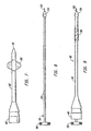
- Pigs. 1-3 illustrate the components of a first. access tube assembly without a removable sheath and thus not as such forming part of the invention.
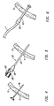
- Figs. 4-6 illustrate use of the access tube assembly of Figs. 1-3 in placing an access tube through a tissue penetration.
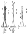
- Figs. 7-10 illustrate the components of a second access tube assembly without a removable sheath and thus not as such forming part of the invention.
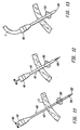
- Figs. 11-13 illustrate use of the access tube assembly of Figs. 7-10 in placing an access tube through a tissue penetration.
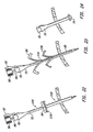
- Figs. 14-19 illustrate the components of a third access tube assembly including a self-introducing dilation nember constructed in accordance with the principles of the present invention.
- Figs. 20-24 illustrate the method of use of the access tube assembly of Figs. 14-19 and forming a tissue penetration and placing an access tube through the tissue penetration.
- Apparatus of the present invention are used to percutaneously place an elastic access tube in a patient to provide access to a target location, typically a hollow body organ or cavity or another region to be treated, such as a cyst.
- the access tube will typically be used for draining target locations, such as the bladder, kidney, chest, lungs, gallbladder, peritoneum, intestines, cysts and the like.
- the access tube will also find use for feeding patients by insertion into the stomach.
- percutaneous it is meant that the access tube will be placed through the patient's outer skin and, optionally, through intermediate tissue and organ structures to reach the desired body cavity or other location. Particular apparatus for percutaneously introducing the access tubes will be described in more detail hereinafter. In some cases, the access tube could also be used to provide peripherally sealed access to the vascular system.
- the access tube comprises an elastic tubular body having an intrinsic length in the range from 2 cm to 20 cm, usually being from 10 cm to 20 cm for drainage and feeding catheters and an intrinsic diameter in the range from 2 mm to 8 mm, usually being from 5 mm to 8 mm for drainage and feeding catheters.
- the tubular body may be composed of any medically acceptable elastic material, such as latex, silicone rubber, and the like.
- the "intrinsic" length and diameter are the length and diameter of the tube while not under axial stress or radially compression. The length may be increased, and the diameter reduced, by placing the tubular body under axial tension, typically using a stylet as described hereinafter.
- the tubular body will be "stretchable" by at least about 20%, usually at least about 30%, and preferably at least about 50%.
- the corresponding reduction in diameter will be at least about 10%, usually at least about 15%, often at least about 20%, and preferably at least about 25%.
- the above dimensions are appropriate for drainage and feeding catheters.
- the dimensions will generally be smaller.
- the intrinsic length will generally be from 2 cm to 10 cm and the intrinsic diameter will generally be from 2 mm to 5 mm.
- the access tube will usually have an expandable anchor at or near its distal end, typically in the form of a Malecot, an inflatable balloon (in the nature of a Foley catheter), a pigtail (in the nature Cope loop catheter), and the like.
- the access tube will usually also have a proximal fitting, both for connecting a drain tube, feeding tube, or the like, to the access tube, and for latching the proximal end of the access tube to the stylet to maintain axial tension and elongation.
- a suction reservoir or drainage bag may be attached via a drain tube which is secured to the proximal fitting.
- a nutrient solution may be provided via a feeding tube which is secured to the proximal fitting.
- the fitting will usually include a hemostatic valve to permit introduction of a vascular catheter and associated guiding catheters, guide wires, and the like.
- vascular catheters are available for both diagnostic procedures, such as angiography and ultrasonic imaging, and interventional procedures, such as angioplasty, atherectomy, laser ablation, stent placement, graft placement, and the like.
- the stylet will be a simple rod structure having a length greater than that of the tubular body of the access tube.
- the length of the stylet will be from 15 cm to 45 cm, usually from 20 cm to 40 cm, and preferably from 20 cm to 30 cm.
- the distal end of the stylet will be adapted to engage or couple to the distal end of the access tube in order to permit axial translation of the stylet to apply the desired tension to the access tube.
- the distal end of the stylet may be a blunt tip, where the blunt tip engages a closed end of the access tube.
- the stylet may have a collar or other fitting for engaging the distal end of the access tube, particularly when the stylet has a sharpened tip which extends distally beyond the distel end of the access tube.
- a sharpened tip is useful to permit self-introduction of the combination of access tube and stylet, as described in more detail hereinafter.
- the assembly of access tube and stylet may further include an elongate dilation member which includes a penetration element for self-introduction.
- the dilation member may be similar to the radially expanding dilator described in US 5 431 676. Briefly, the dilation member will be a tubular body having a distal end, a proximal end, and an axial lumen therebetween. The tubular body will be radially expandable so that the combination of access tube and stylet may be advanced therethrough after the dilation member has been percutaneously introduced.
- the dilation member includes an elastic tubular member covered by a lubricous sheath. The dilation member is introduced using an internal needle which is removed prior to introducing the access tube and sheath. Other radially expansible dilating members would also find use in the present invention.
- a first access tube assembly 10 (Fig. 3) comprises an access tube 12 (Fig. 1) and a stylet 14 (Fig. 2).
- the access tube 12 is shown in its relaxed configuration in Fig. 1 and its axially extended configuration in Fig. 3.
- the profile of the relaxed configuration of the access tube 12 is illustrated in broken line in Fig. 3.
- the access tube 12 includes a Malecot structure 16 at its distal end and a fitting 18 at its proximal end.
- the fitting 18 defines a port (not illustrated) which communicates with a central lumen 20 extending the full length of access tube 12.
- the stylet 14 includes an elongate rod 22 having a blunt tip 24 at its distal end.
- a finger grip 26 is secured to the proximal end of the rod 22 and includes a latch member 28.
- the stylet 14 engages a closed distal tip 30 of the Malecot structure 16 and axially stretches the tubular body of the access tube, as illustrated in Fig. 3.
- the latch member 28 engages a recess 32 formed on the proximal fitting 18. In this way, the access tube 12 can be stretched in order to reduce its diameter, as described above, and maintained in the stretched configuration by the latch member 28.
- the latch mechanism 28 will be located from 3 cm to 40 from the distal end of the stylet, preferably being from 15 cm to 40 for feeding and drainage uses and from 3 cm to 20 cm for vascular access.
- the access tube 12 may be released by depressing the latch member 28, as illustrated in broken line in Fig. 3. The access tube is then free to shorten and radially expand as a result of its elastic nature.
- FIG. 4-6 use of the access tube assembly 10 for placing the access tube 12 through a patient's skin S is illustrated.
- An initial penetration P is formed using a conventional needle or other sharpened instrument 36.
- the needle 36 is then withdrawn and the access tube assembly 10 having the access tube 12 under axial tension is introduced through the penetration P.
- the reduced diameter of the access tube caused by the axial elongation will facilitate introducing the tube through the penetration.
- the latch 28 may be depressed to release the stylet 14, permitting the access tube 12 to axially shorten and radially expand, as illustrated in Fig. 6.
- a feeding or drainage tube T can then be connected to the proximal fitting 18 in a conventional manner.
- the access tube 12 will typically have a hemostatic valve (not shown) on proximal fitting 18.
- a second access tube assembly 40 is illustrated.
- the entire access tube assembly 40 is shown in Pig. 9, with the individual access tube 42 and stylet 44 shown in Figs. 7 and 8, respectively.
- the access tube 42 is similar in many respects to the access tube 12 described previously.
- Access tube 42 includes a proximal fitting 46 and has an open distal port 48.
- An inflatable balloon 50 is located near the distal port 48, and a connector for inflating the balloon 50 will be provided on the proximal fitting 46. To avoid unnecessarily complicating the drawings, the balloon connector fitting is not shown.
- the access tube assembly 40 is designed to be self-introducing.
- a penetration element 52 is disposed at the distal end of stylet 44.
- the entire stylet may be formed from hypotube, where the penetration member 52 as defined by a sharpened tip of the hypotube.
- a collar 54 is disposed on the proxiual side of the penetration member 52 and serves to couple the distal end of the access tube 42, as described in more detail hereinafter.
- a key 56 is formed near the proximal end of the stylet 44 and serves to lock the stylet within a slot (not illustrated) in the proximal fitting 46.
- a finger grip 58 is disposed at the proximal end of the stylet 44.
- the open distal port 48 of the access tube 42 is secured within an annular recess 60 formed between the interior surface of collar 54 and the exterior surface of the hypotube body of stylet 44.
- the access tube will be held with sufficient strength so that the tube may be axially elongated, as shown in Fig. 9.
- the configuration of Fig. 9 may be maintained by locking key 56 within the hub to hold the finger grip 58 spaced proximally from the proximal fitting 46, as illustrated.
- the finger grip 58 will be rotated to release the key 56, and the stylet will be further axially advanced to pull the collar off of the access tube.
- the access tube 42 will then shorten and assume its radially expanded configuration, as shown in broken line in Fig. 10.
- the access tube 40 may be directly introduced through the patient's skin S by piercing the penetrating member 52 at the distal end of the assembly through the skin and any underlying tissue structures to reach the target location.
- the balloon 50 may be inflated, and the collar 54 may be axially advanced to release the distal end of the access tube 42, as illustrated in Fig. 12. This is accomplished by depressing the finger grip 58 within the proximal fitting 46, as illustrated.
- the access tube 42 shortens and assumes its radially expanded configuration.
- the stylet 44 may then be withdrawn, and a feeding, draining, or other tube T may be connected, as illustrated in Fig. 13.
- a hemostasis valve (not shown) will be placed on the fitting 46 and no tubing will be connected.
- An access tube 72 has a Malecot structure 74 (illustrated in Fig. 24) at its distal end 76.
- a proximal housing 78 is similar to the proximal housing 18 illustrated in Figs. 1-3.
- a distal portion of the access tube 72 is covered by a removable sheath 80.
- the sheath 80 will typically have a length from about 10 cm to 20 cm for drainage and feeding tubes or from about 2 cm to 5 cm for vascular access, and will cover approximately half of the access tube 72 in its axially elongated configuration, as illustrated in Fig. 16.
- the removable sheath 80 will typically be formed from a lubricous plastic, such as a PTPE, PEP, or other plastic.
- the sheath will be axially scored or split along a line 82 and will further include a splitable handle 84 at its proximal end.
- the diameter of the sheath will be approximately equal to that of the access tube 72 in its axially tensioned or stretched condition, i.e., from 2 mm to 8 mm.
- a stylet 86 includes an elongate rod 88, a proximal finger grip 90, and a latch member 92.
- the stylet 86 terminates at its distal end in a blunt tip 94.
- Stylet 86 is generally the same as stylet 14 illustrated in Fig. 2.
- Subassembly 100 comprising the access tube 72 elongated by the stylet 86 is illustrated in Fig. 16. Insertion of the stylet 86 causes the distal end of the assembly to assume a tapered, generally conical configuration as illustrated at 102.
- dilation member 110 includes an internal needle assembly 112 in an outer sleeve assembly 114.
- the needle assembly 112 may be a conventional Veress needle comprising hypotube 116 having a sharpened distal tip 118 and a spring-loaded obturator 120.
- the obturator 120 retracts while the needle is being penetrated through tissue, but springs back in the distal direction to protect the sharpened tip 118 from unintentionally damaging internal body organs.
- the Veress needle further includes a proximal connector 122 which permits the introduction of insufflation pressure through an open port 124 on the obturator.
- the construction of such Veress needles is conventional and well described in the medical and patent literature.
- the radially expansible sleeve assembly 114 comprises an inner elastic layer 130, typically formed from latex or silicone rubber, and an outer lubricous covering layer 132, typically formed from PTFE, PEP, or other lubricous material. Veress needle 112 passes through a central lumen of the sleeve assembly 114, and the needle 112 may be withdrawn after the assembly has been percutaneously introduced, as described in more detail hereinafter.
- the sleeve assembly 114 further includes a proximal handle 134.
- the handle 134 will be splitable and will permit separation and removal of the elastic and lubricous cover layers 130 and 132 after the access tube has been introduced. Conveniently, axial score(s) or split(s) will be formed along line 136 to facilitate such removal.
- the dilation member 110 is introduced through the patient's skin S, as illustrated in Fig. 20.
- the dilation member is self-introducing by virtue of the sharpened tip 118 of the Veress needle which is initially located within the dilation member 110.
- the Veress needle 112 is removed, as illustrated in Fig. 21, and the sub-assembly 100 including the access tube 72 and stylet 86 is inserted.
- the outer diameter the region of the subassembly which is covered by removable sheath 80 has a diameter which is larger than the internal lumen of dilation member 110.
- the sleeve assembly 114 will be expanded along its entire length.
- the sleeve assembly 114 may then be removed by breaking apart handle 134 and withdrawing the sleeve, as illustrated in Fig. 23.
- Sheath 80 is then removed by breaking apart handle 134.
- the stylet 86 may be released by depressing latch member 92, allowing the access tube 72 to fully expand radially as illustrated in Fig. 24.
Landscapes
- Health & Medical Sciences (AREA)
- Life Sciences & Earth Sciences (AREA)
- Biophysics (AREA)
- Pulmonology (AREA)
- Engineering & Computer Science (AREA)
- Anesthesiology (AREA)
- Biomedical Technology (AREA)
- Heart & Thoracic Surgery (AREA)
- Hematology (AREA)
- Animal Behavior & Ethology (AREA)
- General Health & Medical Sciences (AREA)
- Public Health (AREA)
- Veterinary Medicine (AREA)
- Media Introduction/Drainage Providing Device (AREA)
- Endoscopes (AREA)
Claims (19)
- Ensemble formant tube d'accès comprenant:caractérisé par:un tube d'accès élastique (12, 42, 72) présentant une extrémité proximale ouverte, une extrémité distale et une lumière centrale (20) s'étendant à partir de l'extrémité proximale vers l'extrémité distale, dans lequel le tube (12, 42, 72) présente une longueur propre et un diamètre externe propre lorsqu'ils ne sont pas sous l'effet d'une tension axiale ou d'une compression radiale,un stylet (14, 44, 86) pouvant être reçu à l'intérieur de la lumière centrale (20) et couplé de manière amovible à l'extrémité distale du tube (12, 42, 72),une gaine amovible (80) recouvrant au moins une partie distale du tube (12, 42, 72) et présentant un diamètre interne qui est inférieur au diamètre externe propre du tube (12, 42, 72).
- Ensemble formant tube d'accès selon la revendication 1, caractérisé en ce que le tube (12, 42, 72) présente un dispositif d'ancrage pouvant être expansé (16, 50, 74) à proximité de son extrémité distale.
- Ensemble formant tube d'accès selon la revendication 2, caractérisé en ce que le dispositif d'ancrage pouvant être expansé est une structure "Malecot" (16, 74) qui est allongée et aplatie lorsque le stylet (14, 44; 86) est introduit sur l'extrémité distale du tube (12, 42, 72).
- Ensemble formant tube d'accès selon la revendication 2, caractérisé en ce que le dispositif d'ancrage pouvant être expansé est un ballonnet gonflable (50).
- Ensemble formant tube d'accès selon la revendication 1, caractérisé en ce que le tube (12, 42, 72) présente une pointe distale fermée (30) dans laquelle est introduit le stylet (14, 44, 86) et au moins un orifice latéral situé de manière proximale par rapport à la pointe distale fermée (30).
- Ensemble formant tube d'accès selon la revendication 5, caractérisé en ce que l'orifice latéral est formé par une ou plusieurs fentes axiales qui s'ouvrent lorsque le tube (12, 42, 72) n'est pas sous tension axiale.
- Ensemble formant tube d'accès selon la revendication 1, caractérisé par un mécanisme de verrouillage (28, 92) sur le stylet (14, 44, 86) afin de fixer de manière amovible l'extrémité proximale du tube (12, 42, 72), dans lequel le mécanisme de verrouillage (28, 92) est situé à une certaine distance par rapport à une extrémité distale du stylet (14, 44, 86) qui est au moins de 20 % supérieure à la longueur propre du tube (12, 42, 72).
- Ensemble formant tube d'accès selon la revendication 7, caractérisé en ce que le tube (12, 42, 72) présente une longueur propre comprise dans la plage de 2 cm à 20 cm et un diamètre externe propre compris dans la plage de 2 mm à 8 mm.
- Ensemble formant tube d'accès selon la revendication 8, caractérisé par un raccord (18, 78) sur l'extrémité proximale du tube (12, 42, 72), lequel raccord (18, 78) est fixé par le mécanisme de verrouillage (28, 92) et le mécanisme de verrouillage (28, 92) est situé à une certaine distance par rapport à l'extrémité distale du stylet (14, 44, 86) dans la plage de 3 cm à 40 cm.
- Ensemble formant tube d'accès selon la revendication 1, dans lequel la gaine amovible (80) et un tube en polymère présentant un diamètre interne compris dans la plage de 2 mm à 8 mm.
- Ensemble formant tube d'accès selon la revendication 10, caractérisé en ce que le tube en polymère est prédécoupé ou fendu axialement (82) sur au moins un côté afin de faciliter la séparation et le retrait de la gaine (80).
- Ensemble formant tube d'accès selon l'une quelconque des revendications 1 à 11, caractérisé en ce que le stylet (14, 44, 86) comprend un élément de pénétration à son extrémité distale afin de faciliter l'introduction percutanée.
- Ensemble formant tube d'accès selon la revendication 12, caractérisé en ce que l'élément de pénétration comprend une pointe distale effilée (52) qui s'étend de manière distale au-delà du tube (12, 42, 72) lorsque le stylet (14, 44, 86) est entièrement reçu à l'intérieur du tube (12, 42, 72).
- Ensemble formant tube d'accès selon la revendication 13, caractérisé en ce que le stylet (14, 44, 86) comprend un cylindre conique à son extrémité distale lequel cylindre conique définit une cavité annulaire destinée à recevoir l'extrémité distale du tube d'accès.
- Ensemble formant tube d'accès selon l'une quelconque des revendications 1 à 14, caractérisé par:un élément de dilatation allongé (110) comprenant un corps tubulaire pouvant être expansé radialement présentant une extrémité proximale, une extrémité distale, une lumière axiale et un élément de pénétration (118) au niveau de l'extrémité distale, dans lequel une extrémité distale conique (102) est formée sur le tube (72) lorsqu'une tension axiale est exercée par le stylet (86), de telle sorte que l'extrémité distale conique (102) facilite l'introduction du tube (72) et du stylet (86) à travers la lumière axiale de l'élément de dilatation allongé (110).
- Ensemble formant tube d'accès selon la revendication 15, caractérisé en ce que l'élément de dilatation allongé (110) comprend, en outre, une gaine amovible formée sur le corps tubulaire pouvant être expansé radialement, dans lequel la gaine recouvre le corps tubulaire lorsque l'élément de dilatation allongé (110) est déplacé vers l'avant de manière percutanée et peut ensuite être retirée afin de permettre l'expansion radiale du corps tubulaire lorsque l'extrémité conique (102) du tube (72) est déplacée vers l'avant à travers ledit corps tubulaire.
- Ensemble formant tube d'accès selon la revendication 15, caractérisé en ce que le corps tubulaire pouvant être expansé radialement est un tube en élastomère ou une tresse tubulaire.
- Ensemble formant tube d'accès selon la revendication 15, caractérisé en ce que l'élément de pénétration comprend un corps pénétrant allongé (112) présentant une pointe distale effilée (118), lequel corps pénétrant (112) est reçu de manière amovible à l'intérieur de la lumière axiale du corps tubulaire pouvant être expansé radialement, la pointe distale effilée (118) s'étendant de manière distale par rapport à celui-ci.
- Ensemble formant tube d'accès selon la revendication 15, caractérisé en ce que l'élément de dilatation allongé (110) comprend, en outre, un dispositif d'ancrage pouvant être expansé à proximité de son extrémité distale.
Priority Applications (1)
| Application Number | Priority Date | Filing Date | Title |
|---|---|---|---|
| EP03002188A EP1334744B1 (fr) | 1994-05-09 | 1995-05-08 | Dispositif d'accès pour cathéterisme |
Applications Claiming Priority (3)
| Application Number | Priority Date | Filing Date | Title |
|---|---|---|---|
| US08/240,059 US5454790A (en) | 1994-05-09 | 1994-05-09 | Method and apparatus for catheterization access |
| US240059 | 1994-05-09 | ||
| PCT/US1995/005736 WO1995030449A1 (fr) | 1994-05-09 | 1995-05-08 | Procede et dispositif d'acces pour catheterisme |
Publications (3)
| Publication Number | Publication Date |
|---|---|
| EP0843569A1 EP0843569A1 (fr) | 1998-05-27 |
| EP0843569A4 EP0843569A4 (fr) | 1998-12-09 |
| EP0843569B1 true EP0843569B1 (fr) | 2003-02-05 |
Family
ID=22904943
Family Applications (2)
| Application Number | Title | Priority Date | Filing Date |
|---|---|---|---|
| EP03002188A Expired - Lifetime EP1334744B1 (fr) | 1994-05-09 | 1995-05-08 | Dispositif d'accès pour cathéterisme |
| EP95919066A Expired - Lifetime EP0843569B1 (fr) | 1994-05-09 | 1995-05-08 | Dispositif d'acces pour catheterisme |
Family Applications Before (1)
| Application Number | Title | Priority Date | Filing Date |
|---|---|---|---|
| EP03002188A Expired - Lifetime EP1334744B1 (fr) | 1994-05-09 | 1995-05-08 | Dispositif d'accès pour cathéterisme |
Country Status (6)
| Country | Link |
|---|---|
| US (1) | US5454790A (fr) |
| EP (2) | EP1334744B1 (fr) |
| JP (3) | JP3660358B2 (fr) |
| AU (1) | AU2476495A (fr) |
| DE (2) | DE69529578T2 (fr) |
| WO (1) | WO1995030449A1 (fr) |
Families Citing this family (237)
| Publication number | Priority date | Publication date | Assignee | Title |
|---|---|---|---|---|
| US5431676A (en) | 1993-03-05 | 1995-07-11 | Innerdyne Medical, Inc. | Trocar system having expandable port |
| US5857999A (en) * | 1995-05-05 | 1999-01-12 | Imagyn Medical Technologies, Inc. | Small diameter introducer for laparoscopic instruments |
| US6991614B2 (en) | 1995-11-07 | 2006-01-31 | Boston Scientific Scimed, Inc. | Ureteral stent for improved patient comfort |
| US6520951B1 (en) | 1996-09-13 | 2003-02-18 | Scimed Life Systems, Inc. | Rapid exchange catheter with detachable hood |
| US6582401B1 (en) | 1996-09-13 | 2003-06-24 | Scimed Life Sytems, Inc. | Multi-size convertible catheter |
| US6096009A (en) | 1996-09-13 | 2000-08-01 | Boston Scientific Corporation | Guidewire and catheter locking device and method |
| US6606515B1 (en) | 1996-09-13 | 2003-08-12 | Scimed Life Systems, Inc. | Guide wire insertion and re-insertion tools and methods of use |
| US6346093B1 (en) | 1996-09-13 | 2002-02-12 | Scimed Life Systems, Inc. | Single operator exchange biliary catheter with common distal lumen |
| US5921971A (en) | 1996-09-13 | 1999-07-13 | Boston Scientific Corporation | Single operator exchange biliary catheter |
| WO1998019730A1 (fr) * | 1996-11-04 | 1998-05-14 | Sherwood Medical Company | Dilatateur a expansion radiale revetu s'utilisant avec des tubes de type gastro-intestinal |
| US5749826A (en) * | 1996-11-06 | 1998-05-12 | Faulkner; James W. | Urinary incontinence control device |
| US5873854A (en) * | 1996-12-23 | 1999-02-23 | Datascope Investment Corp. | Method for percutaneous insertion of catheters |
| US5902282A (en) * | 1996-12-26 | 1999-05-11 | Johnson & Johnson Medical, Inc. | Step-down catheter |
| WO1998029026A2 (fr) * | 1996-12-30 | 1998-07-09 | Imagyn Medical Technologies, Inc. | Dispositif d'acces extensible et son procede de fabrication et d'utilisation |
| US6102884A (en) | 1997-02-07 | 2000-08-15 | Squitieri; Rafael | Squitieri hemodialysis and vascular access systems |
| US6143016A (en) * | 1997-04-21 | 2000-11-07 | Advanced Cardiovascular Systems, Inc. | Sheath and method of use for a stent delivery system |
| US6656160B1 (en) * | 1997-04-29 | 2003-12-02 | Applied Medical Resources Corporation | Insufflation needle apparatus |
| US5836913A (en) * | 1997-05-02 | 1998-11-17 | Innerdyne, Inc. | Device and method for accessing a body cavity |
| US6293952B1 (en) * | 1997-07-31 | 2001-09-25 | Circon Corporation | Medical instrument system for piercing through tissue |
| JP2001513402A (ja) | 1997-08-22 | 2001-09-04 | ダイレクト・セラピューティクス,インコーポレイテッド | 医療処置中における組成物の損失防止装置 |
| US6077250A (en) * | 1997-10-01 | 2000-06-20 | Boston Scientific Corporation | Apparatus and method for percutaneously placing gastrostomy tubes |
| DE69837611T2 (de) | 1997-10-01 | 2007-12-27 | Boston Scientific Ltd., St. Michael | Dilatationssysteme |
| US6030364A (en) | 1997-10-03 | 2000-02-29 | Boston Scientific Corporation | Apparatus and method for percutaneous placement of gastro-intestinal tubes |
| US9498604B2 (en) | 1997-11-12 | 2016-11-22 | Genesis Technologies Llc | Medical device and method |
| US6530923B1 (en) | 1998-02-10 | 2003-03-11 | Artemis Medical, Inc. | Tissue removal methods and apparatus |
| US6270464B1 (en) | 1998-06-22 | 2001-08-07 | Artemis Medical, Inc. | Biopsy localization method and device |
| US6416527B1 (en) * | 1998-01-28 | 2002-07-09 | St. Jude Medical Cardiovascular Group, Inc. | Vessel cutting device |
| JP2002502626A (ja) | 1998-02-10 | 2002-01-29 | アーテミス・メディカル・インコーポレイテッド | 補足装置およびその使用方法 |
| US6602265B2 (en) * | 1998-02-10 | 2003-08-05 | Artemis Medical, Inc. | Tissue separation medical device and method |
| US6450989B2 (en) * | 1998-04-27 | 2002-09-17 | Artemis Medical, Inc. | Dilating and support apparatus with disease inhibitors and methods for use |
| WO1999055285A2 (fr) * | 1998-04-27 | 1999-11-04 | Dubrul William R | Dispositif de dilatation et de soutien renfermant des inhibiteurs de maladie, et son mode d'utilisation |
| US20100036481A1 (en) * | 1998-04-27 | 2010-02-11 | Artemis Medical, Inc. | Cardiovascular Devices and Methods |
| US6332877B1 (en) | 1998-05-12 | 2001-12-25 | Novartis Ag | Ostomy tube placement tip |
| AU4679499A (en) * | 1998-06-10 | 1999-12-30 | Advanced Bypass Technologies, Inc. | Thermal securing anastomosis systems |
| US6245052B1 (en) * | 1998-07-08 | 2001-06-12 | Innerdyne, Inc. | Methods, systems, and kits for implanting articles |
| US6136014A (en) * | 1998-09-01 | 2000-10-24 | Vivant Medical, Inc. | Percutaneous tissue removal device |
| US6033420A (en) * | 1998-09-02 | 2000-03-07 | Embol-X, Inc. | Trocar introducer system and methods of use |
| US6280569B1 (en) * | 1998-10-15 | 2001-08-28 | Andritz-Ahlstrom Inc. | Compression rings for column relief in continuous cooking vessels |
| US6036698A (en) | 1998-10-30 | 2000-03-14 | Vivant Medical, Inc. | Expandable ring percutaneous tissue removal device |
| WO2000067825A1 (fr) * | 1999-05-07 | 2000-11-16 | Microheart, Inc. | Appareil et procede d"administration d"agents therapeutiques et diagnostiques |
| US6692462B2 (en) * | 1999-05-19 | 2004-02-17 | Mackenzie Andrew J. | System and method for establishing vascular access |
| JP4225697B2 (ja) * | 1999-05-19 | 2009-02-18 | インナーダイン, インコーポレイテッド | 脈管へのアクセスを確立するためのシステム |
| JP2003517346A (ja) | 1999-06-04 | 2003-05-27 | アーテミス・メディカル・インコーポレイテッド | 組織除去方法及び装置 |
| US6358238B1 (en) | 1999-09-02 | 2002-03-19 | Scimed Life Systems, Inc. | Expandable micro-catheter |
| US6514248B1 (en) | 1999-10-15 | 2003-02-04 | Neothermia Corporation | Accurate cutting about and into tissue volumes with electrosurgically deployed electrodes |
| US6287304B1 (en) | 1999-10-15 | 2001-09-11 | Neothermia Corporation | Interstitial cauterization of tissue volumes with electrosurgically deployed electrodes |
| US6471659B2 (en) | 1999-12-27 | 2002-10-29 | Neothermia Corporation | Minimally invasive intact recovery of tissue |
| US20030093104A1 (en) * | 1999-10-29 | 2003-05-15 | Bonner Matthew D. | Methods and apparatus for providing intra-pericardial access |
| US7758521B2 (en) * | 1999-10-29 | 2010-07-20 | Medtronic, Inc. | Methods and systems for accessing the pericardial space |
| US20050154370A1 (en) * | 1999-10-29 | 2005-07-14 | Medtronic, Inc. | Methods and systems for providing therapies into the pericardial space |
| US6613062B1 (en) * | 1999-10-29 | 2003-09-02 | Medtronic, Inc. | Method and apparatus for providing intra-pericardial access |
| US6287291B1 (en) | 1999-11-09 | 2001-09-11 | Advanced Cardiovascular Systems, Inc. | Protective sheath for catheters |
| US6277083B1 (en) | 1999-12-27 | 2001-08-21 | Neothermia Corporation | Minimally invasive intact recovery of tissue |
| US6547761B2 (en) | 2000-01-07 | 2003-04-15 | Scimed Life Systems, Inc. | Drainage catheter |
| US7811250B1 (en) | 2000-02-04 | 2010-10-12 | Boston Scientific Scimed, Inc. | Fluid injectable single operator exchange catheters and methods of use |
| US6562049B1 (en) * | 2000-03-01 | 2003-05-13 | Cook Vascular Incorporated | Medical introducer apparatus |
| US6589262B1 (en) * | 2000-03-31 | 2003-07-08 | Medamicus, Inc. | Locking catheter introducing system |
| US6648906B2 (en) | 2000-04-06 | 2003-11-18 | Innercool Therapies, Inc. | Method and apparatus for regulating patient temperature by irrigating the bladder with a fluid |
| US7517352B2 (en) | 2000-04-07 | 2009-04-14 | Bacchus Vascular, Inc. | Devices for percutaneous remote endarterectomy |
| US6558350B1 (en) * | 2000-06-20 | 2003-05-06 | Applied Medical Resources Corp. | Drainage catheter |
| FR2810555B1 (fr) * | 2000-06-26 | 2003-05-30 | Soprane Sa | Catheter reutilisable |
| US20040092879A1 (en) * | 2000-11-06 | 2004-05-13 | Medamicus, Inc. | Safety introducer apparatus and method therefor |
| US7001396B2 (en) * | 2003-03-26 | 2006-02-21 | Enpath Medical, Inc. | Safety introducer assembly and method |
| US6641564B1 (en) * | 2000-11-06 | 2003-11-04 | Medamicus, Inc. | Safety introducer apparatus and method therefor |
| US6764484B2 (en) * | 2001-03-30 | 2004-07-20 | Scimed Life Systems, Inc. | C-channel to o-channel converter for a single operator exchange biliary catheter |
| AU2002317605B2 (en) * | 2001-08-01 | 2008-09-25 | Covidien Lp | Radially dilatable percutaneous access apparatus with introducer seal in handle |
| US6827718B2 (en) | 2001-08-14 | 2004-12-07 | Scimed Life Systems, Inc. | Method of and apparatus for positioning and maintaining the position of endoscopic instruments |
| US6979319B2 (en) * | 2001-12-31 | 2005-12-27 | Cardiac Pacemakers, Inc. | Telescoping guide catheter with peel-away outer sheath |
| US7083595B2 (en) | 2002-05-01 | 2006-08-01 | Scimed Lipe Systems, Inc. | Medical catheter assembly and method of using the same |
| US7377897B1 (en) | 2002-05-02 | 2008-05-27 | Kunkel Sanford S | Portal device |
| US20050256503A1 (en) * | 2002-05-07 | 2005-11-17 | Cardiac Pacemakers, Inc. | Tapered catheter delivery system |
| EP1503677B1 (fr) * | 2002-05-16 | 2011-05-04 | Applied Medical Resources Corporation | Obturateur pointe conique |
| JP3808806B2 (ja) * | 2002-06-26 | 2006-08-16 | メディキット株式会社 | 留置針 |
| US6793678B2 (en) | 2002-06-27 | 2004-09-21 | Depuy Acromed, Inc. | Prosthetic intervertebral motion disc having dampening |
| US7329268B2 (en) * | 2002-07-02 | 2008-02-12 | Warsaw Orthopedic, Inc. | Expandable percutaneous sheath |
| DE20210394U1 (de) | 2002-07-04 | 2002-09-12 | B. Braun Melsungen Ag, 34212 Melsungen | Kathetereinführvorrichtung |
| JP2006507032A (ja) * | 2002-07-16 | 2006-03-02 | アプライド メディカル リソーシーズ コーポレイション | 排出カテーテル |
| US7005026B2 (en) * | 2002-11-15 | 2006-02-28 | Applied Medical Resources Corporation | Kink-resistant access sheath and method of making same |
| AU2003295878B2 (en) | 2002-11-22 | 2008-07-10 | Covidien Lp | Sheath introduction apparatus and method |
| US6893393B2 (en) | 2003-02-19 | 2005-05-17 | Boston Scientific Scimed., Inc. | Guidewire locking device and method |
| US7655021B2 (en) * | 2003-03-10 | 2010-02-02 | Boston Scientific Scimed, Inc. | Dilator with expandable member |
| US7479150B2 (en) | 2003-09-19 | 2009-01-20 | Tyco Healthcare Group Lp | Trocar insertion apparatus |
| US7762977B2 (en) * | 2003-10-08 | 2010-07-27 | Hemosphere, Inc. | Device and method for vascular access |
| AU2004220757B2 (en) * | 2003-10-17 | 2010-06-17 | Covidien Lp | Surgical access device and manufacture thereof |
| US9241735B2 (en) | 2003-12-05 | 2016-01-26 | Onset Medical Corporation | Expandable percutaneous sheath |
| US7780692B2 (en) | 2003-12-05 | 2010-08-24 | Onset Medical Corporation | Expandable percutaneous sheath |
| US20050182387A1 (en) * | 2004-02-13 | 2005-08-18 | Cardiac Pacemakers, Inc. | Peel-away catheter shaft |
| WO2005084563A1 (fr) * | 2004-02-27 | 2005-09-15 | Cook Vascular Incorporated | Dispositif destine a extraire une structure allongee implantee dans des tissus biologiques |
| US7425202B2 (en) * | 2004-03-05 | 2008-09-16 | Percutaneous Systems, Inc. | Non-seeding biopsy device and method |
| US20050197627A1 (en) | 2004-03-05 | 2005-09-08 | Percutaneous Systems, Inc. | Method and system for deploying protective sleeve in intraluminal catherization and dilation |
| US7972292B2 (en) | 2005-07-06 | 2011-07-05 | Percutaneous Systems, Inc. | Methods and apparatus for deploying ureteral stents |
| US7462183B2 (en) * | 2004-07-07 | 2008-12-09 | Percutaneous Systems, Inc. | Methods for deploying conformed structures in body lumens |
| US7883516B2 (en) * | 2004-07-07 | 2011-02-08 | Percutaneous Systems, Inc. | Methods for removing kidney stones from the ureter |
| US20060015131A1 (en) * | 2004-07-15 | 2006-01-19 | Kierce Paul C | Cannula for in utero surgery |
| US9387313B2 (en) | 2004-08-03 | 2016-07-12 | Interventional Spine, Inc. | Telescopic percutaneous tissue dilation systems and related methods |
| CN101001575A (zh) * | 2004-08-17 | 2007-07-18 | 株式会社Jms | 血管剥离工具 |
| US7892203B2 (en) | 2004-09-09 | 2011-02-22 | Onset Medical Corporation | Expandable transluminal sheath |
| US20060135981A1 (en) | 2004-09-09 | 2006-06-22 | Jay Lenker | Expandable transluminal sheath |
| US20060135962A1 (en) | 2004-09-09 | 2006-06-22 | Kick George F | Expandable trans-septal sheath |
| JP4355671B2 (ja) * | 2004-10-04 | 2009-11-04 | 規方 田熊 | 胃瘻用チューブの再挿入器具 |
| US7329233B2 (en) * | 2004-10-05 | 2008-02-12 | Tyco Healthcare Group Lp | Surgical system for laparoscopic surgery |
| US20060161190A1 (en) * | 2005-01-19 | 2006-07-20 | Gadberry Donald L | Disposable laparoscopic instrument |
| US8480629B2 (en) | 2005-01-28 | 2013-07-09 | Boston Scientific Scimed, Inc. | Universal utility board for use with medical devices and methods of use |
| US7803142B2 (en) | 2005-02-02 | 2010-09-28 | Summit Access Llc | Microtaper needle and method of use |
| US20060212062A1 (en) * | 2005-03-16 | 2006-09-21 | David Farascioni | Radially expandable access system including trocar seal |
| US20060259061A1 (en) * | 2005-04-22 | 2006-11-16 | Kick George F | Expandable sheath for percutaneous upper gastrointestinal tract access |
| JP2006314744A (ja) * | 2005-05-12 | 2006-11-24 | Ir Medical Kobo:Kk | 透明な脳穿刺用套管針 |
| US8092481B2 (en) | 2005-06-03 | 2012-01-10 | Onset Medical Corporation | Expandable percutaneous sheath |
| DE602006005674D1 (de) | 2005-07-06 | 2009-04-23 | Vascular Pathways Inc | Gerät zur intravenösen kathetereinführung und verwendungsverfahren |
| US8172801B2 (en) * | 2005-09-15 | 2012-05-08 | Boston Scientific Scimed, Inc. | Method for positioning a catheter guide element in a patient and kit for use in said method |
| US8709018B2 (en) * | 2005-09-16 | 2014-04-29 | Applied Medical Technology, Inc. | Non-balloon low profile feed device with insertion/removal tool |
| US20070073107A1 (en) * | 2005-09-23 | 2007-03-29 | Percutaneous Systems, Inc. | Methods and systems for sheathing tubular medical instruments |
| US7811251B2 (en) * | 2005-10-13 | 2010-10-12 | Tyco Healthcare Group Lp | Trocar anchor |
| US20070106233A1 (en) * | 2005-10-20 | 2007-05-10 | Percutaneous Systems, Inc. | Systems and methods for dilating and accessing body lumens |
| US20070167901A1 (en) * | 2005-11-17 | 2007-07-19 | Herrig Judson A | Self-sealing residual compressive stress graft for dialysis |
| US8128636B2 (en) | 2006-02-13 | 2012-03-06 | Cook Medical Technologies Llc | Device and method for removing lumenless leads |
| US8308691B2 (en) | 2006-11-03 | 2012-11-13 | B. Braun Melsungen Ag | Catheter assembly and components thereof |
| CA2594239A1 (fr) * | 2006-08-02 | 2008-02-02 | Tyco Healthcare Group Lp | Dispositif d'assistance de stabilisation pour trocart |
| US7798998B2 (en) * | 2006-10-06 | 2010-09-21 | Surgiquest, Inc. | Elastically deformable surgical access device |
| US7806870B2 (en) * | 2006-10-06 | 2010-10-05 | Surgiquest, Incorporated | Elastically deformable surgical access device having telescoping guide tube |
| US8449503B2 (en) | 2010-11-30 | 2013-05-28 | Custom Medical Applications | Neural injection system and related methods |
| US9888940B2 (en) * | 2006-09-11 | 2018-02-13 | Custom Medical Applications | Neural injection system and related methods |
| US8795235B2 (en) | 2006-10-06 | 2014-08-05 | Surgiquest, Inc. | Devices for and methods of performing minimally-invasive surgical procedures through a single incision |
| JP4994775B2 (ja) | 2006-10-12 | 2012-08-08 | 日本コヴィディエン株式会社 | 針先保護具 |
| US8105382B2 (en) | 2006-12-07 | 2012-01-31 | Interventional Spine, Inc. | Intervertebral implant |
| WO2008079828A2 (fr) | 2006-12-20 | 2008-07-03 | Onset Medical Corporation | Gaine transseptale dilatable |
| WO2008085712A1 (fr) | 2007-01-03 | 2008-07-17 | Boston Scientific Limited | Procédé et appareil pour un accès biliaire et une récupération de calcul |
| US20080195135A1 (en) * | 2007-02-12 | 2008-08-14 | Alcon, Inc. | Surgical Probe |
| ES2592719T3 (es) | 2007-02-12 | 2016-12-01 | Boston Scientific Limited | Tapa de endoscopio |
| JP5139518B2 (ja) | 2007-05-07 | 2013-02-06 | バスキュラー・パスウェイズ・インコーポレイテッド | 静脈カテーテル挿入装置 |
| US8900307B2 (en) | 2007-06-26 | 2014-12-02 | DePuy Synthes Products, LLC | Highly lordosed fusion cage |
| US7879066B2 (en) * | 2007-07-13 | 2011-02-01 | Percutaneous Sustems, Inc. | Apparatus for occluding body lumens |
| US8475489B2 (en) * | 2007-07-13 | 2013-07-02 | Percutaneous Systems, Inc. | Apparatus for occluding body lumens |
| US8469987B2 (en) * | 2007-08-09 | 2013-06-25 | Senorx, Inc. | Split sheath for trocar assembly |
| US8795326B2 (en) | 2007-10-05 | 2014-08-05 | Covidien Lp | Expanding seal anchor for single incision surgery |
| AU2009205896A1 (en) | 2008-01-17 | 2009-07-23 | Synthes Gmbh | An expandable intervertebral implant and associated method of manufacturing the same |
| GB0802201D0 (en) * | 2008-02-06 | 2008-03-12 | Isis Innovation | Treatment system |
| US8388521B2 (en) | 2008-05-19 | 2013-03-05 | Boston Scientific Scimed, Inc. | Integrated locking device with active sealing |
| US8343041B2 (en) | 2008-05-19 | 2013-01-01 | Boston Scientific Scimed, Inc. | Integrated locking device with passive sealing |
| AU2009219220A1 (en) * | 2008-02-26 | 2009-09-03 | Iyunni Venkata Sesha Sayi Nath | Feeding tube |
| US20120095432A1 (en) * | 2010-10-15 | 2012-04-19 | Nath Iyunni Venkata Sesha Sayi | Catheter and method of insertion |
| US8079973B2 (en) | 2008-03-05 | 2011-12-20 | Hemosphere Inc. | Vascular access system |
| US20110295181A1 (en) | 2008-03-05 | 2011-12-01 | Hemosphere, Inc. | Implantable and removable customizable body conduit |
| BRPI0910325A8 (pt) | 2008-04-05 | 2019-01-29 | Synthes Gmbh | implante intervertebral expansível |
| US20100004601A1 (en) * | 2008-07-03 | 2010-01-07 | Cook Incorporated | Malecot gastronomy tube with splittable sheath |
| US8986291B2 (en) * | 2008-12-01 | 2015-03-24 | Percutaneous Systems, Inc. | Methods and systems for capturing and removing urinary stones from body cavities |
| US9526620B2 (en) | 2009-03-30 | 2016-12-27 | DePuy Synthes Products, Inc. | Zero profile spinal fusion cage |
| GB2472058B (en) * | 2009-07-23 | 2014-05-14 | Mediplus Ltd | Lock mechanism for a catheter |
| US9393129B2 (en) | 2009-12-10 | 2016-07-19 | DePuy Synthes Products, Inc. | Bellows-like expandable interbody fusion cage |
| WO2011112800A2 (fr) * | 2010-03-10 | 2011-09-15 | The Cleveland Clinic Foudation | Ensemble cathéter |
| US8449512B2 (en) | 2010-04-09 | 2013-05-28 | Davinci Biomedical Research Products Inc. | Stoma stabilitating device and method |
| US8932258B2 (en) | 2010-05-14 | 2015-01-13 | C. R. Bard, Inc. | Catheter placement device and method |
| US9872971B2 (en) | 2010-05-14 | 2018-01-23 | C. R. Bard, Inc. | Guidewire extension system for a catheter placement device |
| US11925779B2 (en) | 2010-05-14 | 2024-03-12 | C. R. Bard, Inc. | Catheter insertion device including top-mounted advancement components |
| US9950139B2 (en) | 2010-05-14 | 2018-04-24 | C. R. Bard, Inc. | Catheter placement device including guidewire and catheter control elements |
| US10384039B2 (en) | 2010-05-14 | 2019-08-20 | C. R. Bard, Inc. | Catheter insertion device including top-mounted advancement components |
| US10335577B2 (en) | 2010-05-19 | 2019-07-02 | Nfinium Vascular Technologies, Llc | Augmented delivery catheter and method |
| US9763678B2 (en) | 2010-06-24 | 2017-09-19 | DePuy Synthes Products, Inc. | Multi-segment lateral cage adapted to flex substantially in the coronal plane |
| US8979860B2 (en) | 2010-06-24 | 2015-03-17 | DePuy Synthes Products. LLC | Enhanced cage insertion device |
| AU2011271465B2 (en) | 2010-06-29 | 2015-03-19 | Synthes Gmbh | Distractible intervertebral implant |
| US9561094B2 (en) | 2010-07-23 | 2017-02-07 | Nfinium Vascular Technologies, Llc | Devices and methods for treating venous diseases |
| US20120035585A1 (en) * | 2010-08-03 | 2012-02-09 | Cook Incorporated | Tapered venous access introducer |
| US9272085B2 (en) | 2010-08-03 | 2016-03-01 | Cook Medical Technologies Llc | Method of introducing a catheter |
| US9402732B2 (en) | 2010-10-11 | 2016-08-02 | DePuy Synthes Products, Inc. | Expandable interspinous process spacer implant |
| JP5126910B2 (ja) * | 2010-10-29 | 2013-01-23 | 朝日インテック株式会社 | 補助ダイレータとこれを用いたカテーテル組立体 |
| US8690833B2 (en) | 2011-01-31 | 2014-04-08 | Vascular Pathways, Inc. | Intravenous catheter and insertion device with reduced blood spatter |
| EP3563898B1 (fr) | 2011-02-25 | 2020-11-11 | C.R. Bard, Inc. | Dispositif d'introduction de composant médical comprenant une aiguille rétractable |
| US8486024B2 (en) | 2011-04-27 | 2013-07-16 | Covidien Lp | Safety IV catheter assemblies |
| USD903101S1 (en) | 2011-05-13 | 2020-11-24 | C. R. Bard, Inc. | Catheter |
| US10849771B2 (en) | 2011-06-27 | 2020-12-01 | Boston Scientific Scimed, Inc. | Stent delivery systems and methods for making and using stent delivery systems |
| EP2753376B1 (fr) | 2011-09-06 | 2015-07-01 | Hemosphere Inc. | Système d'accès vasculaire doté d'un connecteur |
| US20130103000A1 (en) * | 2011-09-09 | 2013-04-25 | The Cleveland Clinic Foundation | Catheter assembly |
| WO2013048768A1 (fr) | 2011-09-26 | 2013-04-04 | Covidien Lp | Ensemble cathéter et aiguille de sécurité intraveineux |
| WO2013048975A1 (fr) | 2011-09-26 | 2013-04-04 | Covidien Lp | Cathéter à sécurité |
| US8834422B2 (en) | 2011-10-14 | 2014-09-16 | Covidien Lp | Vascular access assembly and safety device |
| CN104254584A (zh) | 2012-04-27 | 2014-12-31 | 株式会社德山 | 光致变色固化性组合物 |
| US8986264B2 (en) * | 2012-05-08 | 2015-03-24 | Greatbatch Ltd. | Transseptal needle apparatus |
| US9358039B2 (en) | 2012-05-08 | 2016-06-07 | Greatbatch Ltd. | Transseptal needle apparatus |
| CA2879882A1 (fr) | 2012-07-23 | 2014-01-30 | University Of Utah Research Foundation | Sonde urinaire a demeure |
| WO2014018098A1 (fr) | 2012-07-26 | 2014-01-30 | DePuy Synthes Products, LLC | Implant expansible |
| US20140067069A1 (en) | 2012-08-30 | 2014-03-06 | Interventional Spine, Inc. | Artificial disc |
| US10022520B2 (en) * | 2012-12-17 | 2018-07-17 | Nico Corporation | Surgical access system |
| CN105102054B (zh) | 2013-01-30 | 2018-04-20 | 血管通路股份有限公司 | 用于静脉穿刺和导管放置的系统和方法 |
| US9717601B2 (en) | 2013-02-28 | 2017-08-01 | DePuy Synthes Products, Inc. | Expandable intervertebral implant, system, kit and method |
| US9522070B2 (en) | 2013-03-07 | 2016-12-20 | Interventional Spine, Inc. | Intervertebral implant |
| CN105377150B (zh) | 2013-04-16 | 2017-12-05 | 泰利福医疗公司 | 带有可重复使用的手柄和可拆卸的针组件的针式腹腔镜器械 |
| JP2016516552A (ja) * | 2013-05-03 | 2016-06-09 | シー・アール・バード・インコーポレーテッドC R Bard Incorporated | 剥がすことができる保護シース |
| US10856901B2 (en) | 2013-09-18 | 2020-12-08 | Teleflex Medical Incorporated | Exchanger surgical access port assembly and methods of use |
| CA2924601C (fr) * | 2013-09-24 | 2022-05-31 | Merit Medical Systems, Inc. | Ensemble et methodes de guidage d'instrument chirurgical |
| US10682453B2 (en) | 2013-12-20 | 2020-06-16 | Merit Medical Systems, Inc. | Vascular access system with reinforcement member |
| WO2015134568A1 (fr) * | 2014-03-06 | 2015-09-11 | Barbara Schulz | Cathéter à ballonnet amélioré à gaine amovible pelable destiné à être utilisé pour induire le travail |
| EP3151904A4 (fr) | 2014-06-04 | 2018-02-14 | Nfinium Vascular Technologies, LLC | Dispositif vasculaire à faible force radiale et procédé d'occlusion |
| US9545264B2 (en) * | 2014-06-06 | 2017-01-17 | Surgiquest, Inc. | Trocars and obturators |
| JP6400682B2 (ja) * | 2014-07-15 | 2018-10-03 | テレフレックス メディカル インコーポレイテッド | 交換式外科用アクセスポート組立体 |
| WO2016037127A1 (fr) | 2014-09-05 | 2016-03-10 | C.R. Bard, Inc. | Dispositif d'insertion de cathéter comprenant une aiguille rétractable |
| US11426290B2 (en) | 2015-03-06 | 2022-08-30 | DePuy Synthes Products, Inc. | Expandable intervertebral implant, system, kit and method |
| USD903100S1 (en) | 2015-05-01 | 2020-11-24 | C. R. Bard, Inc. | Catheter placement device |
| WO2016187037A1 (fr) | 2015-05-15 | 2016-11-24 | C.R.Bard, Inc. | Dispositif de mise en place de cathéter comprenant un composant de protection de l'aiguille extensible |
| US9913727B2 (en) | 2015-07-02 | 2018-03-13 | Medos International Sarl | Expandable implant |
| US10117675B2 (en) * | 2015-07-28 | 2018-11-06 | Covidien Lp | Trocar tip protector |
| CN109640889B (zh) | 2016-06-28 | 2021-07-30 | Eit 新兴移植技术股份有限公司 | 可扩张的角度可调节式关节运动椎间保持架 |
| JP6995789B2 (ja) | 2016-06-28 | 2022-01-17 | イーアイティー・エマージング・インプラント・テクノロジーズ・ゲーエムベーハー | 拡張可能かつ角度調節可能な椎間ケージ |
| JP6921660B2 (ja) * | 2016-07-06 | 2021-08-18 | 株式会社カネカ | ガイドワイヤサポートカテーテル |
| CA3032247A1 (fr) * | 2016-08-03 | 2018-02-08 | Vascular Barcelona Devices, S.L. | Dispositifs a catheter, ensembles aiguilles, kits et procedes associes |
| DE112016007187T5 (de) * | 2016-08-30 | 2019-05-23 | Spiration, Inc. D/B/A Olympus Respiratory America | Griffsperre für medizinische vorrichtung |
| CN109715093B (zh) | 2016-09-12 | 2020-11-06 | C·R·巴德股份有限公司 | 导管插入装置的血液控制 |
| US10537436B2 (en) | 2016-11-01 | 2020-01-21 | DePuy Synthes Products, Inc. | Curved expandable cage |
| US10499920B2 (en) | 2016-11-10 | 2019-12-10 | Merit Medical Systems, Inc. | Anchor device for vascular anastomosis |
| US10888433B2 (en) | 2016-12-14 | 2021-01-12 | DePuy Synthes Products, Inc. | Intervertebral implant inserter and related methods |
| US11383072B2 (en) | 2017-01-12 | 2022-07-12 | Merit Medical Systems, Inc. | Methods and systems for selection and use of connectors between conduits |
| WO2018140306A1 (fr) | 2017-01-25 | 2018-08-02 | Merit Medical Systems, Inc. | Procédés et systèmes pour faciliter un écoulement laminaire entre des conduits |
| US11400260B2 (en) | 2017-03-01 | 2022-08-02 | C. R. Bard, Inc. | Catheter insertion device |
| WO2018164945A1 (fr) | 2017-03-06 | 2018-09-13 | Merit Medical Systems, Inc. | Systèmes et procédés de décoagulation d'ensemble d'accès vasculaire |
| WO2018175850A1 (fr) | 2017-03-24 | 2018-09-27 | Merit Medical Systems, Inc. | Ensembles vasculaires sous-cutanés pour améliorer la circulation sanguine et dispositifs et procédés associés |
| US10398563B2 (en) | 2017-05-08 | 2019-09-03 | Medos International Sarl | Expandable cage |
| US11344424B2 (en) | 2017-06-14 | 2022-05-31 | Medos International Sarl | Expandable intervertebral implant and related methods |
| US10940016B2 (en) | 2017-07-05 | 2021-03-09 | Medos International Sarl | Expandable intervertebral fusion cage |
| US11179543B2 (en) | 2017-07-14 | 2021-11-23 | Merit Medical Systems, Inc. | Releasable conduit connectors |
| US9987464B1 (en) | 2017-07-20 | 2018-06-05 | Donaco Medical Design, LLC | Urinary catheter insertion device and kit |
| US11911585B2 (en) | 2017-07-20 | 2024-02-27 | Merit Medical Systems, Inc. | Methods and systems for coupling conduits |
| CN115813455A (zh) | 2017-08-11 | 2023-03-21 | 波士顿科学国际有限公司 | 用于内窥镜的活检帽 |
| WO2019089569A1 (fr) | 2017-10-31 | 2019-05-09 | Merit Medical Systems, Inc. | Ensembles vasculaires sous-cutanés pour améliorer la circulation sanguine et dispositifs et procédés associés |
| CN115671504A (zh) | 2018-03-07 | 2023-02-03 | 巴德阿克塞斯系统股份有限公司 | 用于医疗装置插入系统的导丝推进和血液闪回系统 |
| USD921884S1 (en) | 2018-07-27 | 2021-06-08 | Bard Access Systems, Inc. | Catheter insertion device |
| US11389627B1 (en) | 2018-10-02 | 2022-07-19 | Lutonix Inc. | Balloon protectors, balloon-catheter assemblies, and methods thereof |
| US11446156B2 (en) | 2018-10-25 | 2022-09-20 | Medos International Sarl | Expandable intervertebral implant, inserter instrument, and related methods |
| WO2020137899A1 (fr) * | 2018-12-26 | 2020-07-02 | テルモ株式会社 | Ensemble cathéter |
| US20220023513A1 (en) * | 2019-03-01 | 2022-01-27 | Nailmark Medical, Llc | Methods of chest tube insertion |
| US11344309B2 (en) * | 2019-07-05 | 2022-05-31 | Covidien Lp | Circular stapling instruments |
| CN213312819U (zh) | 2019-08-19 | 2021-06-01 | 贝克顿·迪金森公司 | 中线导管放置装置 |
| WO2021054980A1 (fr) | 2019-09-20 | 2021-03-25 | Bard Peripheral Vascular, Inc. | Dispositif de placement de cathéter intraveineux |
| US11426286B2 (en) | 2020-03-06 | 2022-08-30 | Eit Emerging Implant Technologies Gmbh | Expandable intervertebral implant |
| JP7593844B2 (ja) * | 2021-03-18 | 2024-12-03 | テルモ株式会社 | カテーテルシステム |
| US11850160B2 (en) | 2021-03-26 | 2023-12-26 | Medos International Sarl | Expandable lordotic intervertebral fusion cage |
| US11752009B2 (en) | 2021-04-06 | 2023-09-12 | Medos International Sarl | Expandable intervertebral fusion cage |
| US12090064B2 (en) | 2022-03-01 | 2024-09-17 | Medos International Sarl | Stabilization members for expandable intervertebral implants, and related systems and methods |
| US20240225654A9 (en) * | 2022-10-20 | 2024-07-11 | Trisalus Life Sciences, Inc. | Therapeutic treatment device with braided microvalve occluder having collapsible cover |
Family Cites Families (22)
| Publication number | Priority date | Publication date | Assignee | Title |
|---|---|---|---|---|
| US2616429A (en) * | 1948-11-27 | 1952-11-04 | Merenlender Israel | Draining probe |
| DE885917C (de) * | 1951-05-17 | 1953-08-10 | Martin Dr Med Boesl | Dauerkatheter aus elastischem Material |
| US3490457A (en) * | 1967-02-06 | 1970-01-20 | Roy A Petersen | Catheter |
| US3713447A (en) * | 1971-08-16 | 1973-01-30 | E Adair | Suprapubic shunt |
| US3948271A (en) * | 1972-11-07 | 1976-04-06 | Taichiro Akiyama | Drain for the eardrum and apparatus for introducing the same |
| US3890970A (en) * | 1974-01-21 | 1975-06-24 | Robert L Gullen | Retention cannula or catheter and applicator |
| US3961632A (en) * | 1974-12-13 | 1976-06-08 | Moossun Mohamed H | Stomach intubation and catheter placement system |
| US4112932A (en) * | 1977-02-24 | 1978-09-12 | Chiulli Robert D | Laparoscopic cannula |
| US4141364A (en) * | 1977-03-18 | 1979-02-27 | Jorge Schultze | Expandable endotracheal or urethral tube |
| US4593687A (en) * | 1983-10-31 | 1986-06-10 | Gray Leo C | Endotracheal catheter |
| US4589868A (en) * | 1984-03-12 | 1986-05-20 | Dretler Stephen P | Expandable dilator-catheter |
| US4871358A (en) * | 1987-11-09 | 1989-10-03 | Gold Steven K | Externally-based inversionary tube |
| US4867524A (en) * | 1988-09-08 | 1989-09-19 | United Technologies Corporation | Metallic bond for mounting of optical fibers to integrated optical chips |
| US5074867A (en) * | 1990-05-18 | 1991-12-24 | Wilk Peter J | Surgical instrument assembly and related surgical method |
| US5102401A (en) * | 1990-08-22 | 1992-04-07 | Becton, Dickinson And Company | Expandable catheter having hydrophobic surface |
| US5176649A (en) * | 1991-01-28 | 1993-01-05 | Akio Wakabayashi | Insertion device for use with curved, rigid endoscopic instruments and the like |
| US5183464A (en) * | 1991-05-17 | 1993-02-02 | Interventional Thermodynamics, Inc. | Radially expandable dilator |
| US5098392A (en) * | 1991-06-28 | 1992-03-24 | Fleischhacker John J | Locking dilator for peel away introducer sheath |
| US5183471A (en) * | 1992-01-24 | 1993-02-02 | Wilk Peter J | Laparoscopic cannula |
| US5248302A (en) * | 1992-08-05 | 1993-09-28 | Biosearch Medical Products Inc. | Percutaneous obturatable internal anchoring device |
| US5344439A (en) * | 1992-10-30 | 1994-09-06 | Medtronic, Inc. | Catheter with retractable anchor mechanism |
| US5320611A (en) * | 1993-02-04 | 1994-06-14 | Peter M. Bonutti | Expandable cannula having longitudinal wire and method of use |
-
1994
- 1994-05-09 US US08/240,059 patent/US5454790A/en not_active Expired - Lifetime
-
1995
- 1995-05-08 EP EP03002188A patent/EP1334744B1/fr not_active Expired - Lifetime
- 1995-05-08 AU AU24764/95A patent/AU2476495A/en not_active Abandoned
- 1995-05-08 DE DE69529578T patent/DE69529578T2/de not_active Expired - Lifetime
- 1995-05-08 EP EP95919066A patent/EP0843569B1/fr not_active Expired - Lifetime
- 1995-05-08 JP JP52916595A patent/JP3660358B2/ja not_active Expired - Fee Related
- 1995-05-08 DE DE69534481T patent/DE69534481T2/de not_active Expired - Lifetime
- 1995-05-08 WO PCT/US1995/005736 patent/WO1995030449A1/fr not_active Ceased
-
2004
- 2004-12-15 JP JP2004363342A patent/JP2005161065A/ja not_active Withdrawn
-
2010
- 2010-03-24 JP JP2010067514A patent/JP5032622B2/ja not_active Expired - Lifetime
Also Published As
| Publication number | Publication date |
|---|---|
| DE69534481T2 (de) | 2006-06-14 |
| US5454790A (en) | 1995-10-03 |
| AU2476495A (en) | 1995-11-29 |
| EP0843569A1 (fr) | 1998-05-27 |
| JP5032622B2 (ja) | 2012-09-26 |
| DE69529578T2 (de) | 2003-12-11 |
| JPH09512732A (ja) | 1997-12-22 |
| EP1334744A2 (fr) | 2003-08-13 |
| EP1334744B1 (fr) | 2005-09-21 |
| DE69534481D1 (de) | 2006-02-02 |
| EP0843569A4 (fr) | 1998-12-09 |
| JP3660358B2 (ja) | 2005-06-15 |
| DE69529578D1 (de) | 2003-03-13 |
| JP2011050730A (ja) | 2011-03-17 |
| EP1334744A3 (fr) | 2003-08-27 |
| JP2005161065A (ja) | 2005-06-23 |
| WO1995030449A1 (fr) | 1995-11-16 |
Similar Documents
| Publication | Publication Date | Title |
|---|---|---|
| EP1334744B1 (fr) | Dispositif d'accès pour cathéterisme | |
| AU654710B2 (en) | Radially expandable dilator | |
| US6685671B1 (en) | Balloon catheter for puncturing, medical tube introduction device using the catheter and method for use thereof | |
| CA2430749C (fr) | Systeme et procede pour etablir un acces vasculaire | |
| US5290249A (en) | Surgical access sheath | |
| US4710181A (en) | Variable diameter catheter | |
| US6093173A (en) | Introducer/dilator with balloon protection and methods of use | |
| JP3073019B2 (ja) | 胃瘻形成術用カテーテル・システム | |
| US4738666A (en) | Variable diameter catheter | |
| US6706017B1 (en) | Percutaneous ostomy device and method for creating a stoma and implanting a canula | |
| US5275611A (en) | Tension guide and dilator | |
| CA2754247C (fr) | Catheter et methode d'insertion | |
| US20050197627A1 (en) | Method and system for deploying protective sleeve in intraluminal catherization and dilation | |
| CA2052541A1 (fr) | Appareil medical pour chirurgie endoscopique et methode connexe | |
| WO1995012427A1 (fr) | Instrument, systeme, trousse et procede de catheterisme | |
| US9089663B2 (en) | Percutaneous access device | |
| AU2004233451A1 (en) | Percutaneous plug |
Legal Events
| Date | Code | Title | Description |
|---|---|---|---|
| PUAI | Public reference made under article 153(3) epc to a published international application that has entered the european phase |
Free format text: ORIGINAL CODE: 0009012 |
|
| 17P | Request for examination filed |
Effective date: 19961204 |
|
| AK | Designated contracting states |
Kind code of ref document: A1 Designated state(s): DE FR GB IT |
|
| A4 | Supplementary search report drawn up and despatched |
Effective date: 19981027 |
|
| AK | Designated contracting states |
Kind code of ref document: A4 Designated state(s): DE FR GB IT |
|
| RAP3 | Party data changed (applicant data changed or rights of an application transferred) |
Owner name: INNERDYNE, INC. |
|
| 17Q | First examination report despatched |
Effective date: 20010214 |
|
| GRAG | Despatch of communication of intention to grant |
Free format text: ORIGINAL CODE: EPIDOS AGRA |
|
| RTI1 | Title (correction) |
Free format text: APPARATUS FOR CATHETERIZATION ACCESS |
|
| GRAG | Despatch of communication of intention to grant |
Free format text: ORIGINAL CODE: EPIDOS AGRA |
|
| GRAG | Despatch of communication of intention to grant |
Free format text: ORIGINAL CODE: EPIDOS AGRA |
|
| GRAH | Despatch of communication of intention to grant a patent |
Free format text: ORIGINAL CODE: EPIDOS IGRA |
|
| GRAH | Despatch of communication of intention to grant a patent |
Free format text: ORIGINAL CODE: EPIDOS IGRA |
|
| GRAA | (expected) grant |
Free format text: ORIGINAL CODE: 0009210 |
|
| AK | Designated contracting states |
Designated state(s): DE FR GB IT |
|
| REG | Reference to a national code |
Ref country code: GB Ref legal event code: FG4D |
|
| REF | Corresponds to: |
Ref document number: 69529578 Country of ref document: DE Date of ref document: 20030313 Kind code of ref document: P |
|
| ET | Fr: translation filed | ||
| PLBE | No opposition filed within time limit |
Free format text: ORIGINAL CODE: 0009261 |
|
| STAA | Information on the status of an ep patent application or granted ep patent |
Free format text: STATUS: NO OPPOSITION FILED WITHIN TIME LIMIT |
|
| 26N | No opposition filed |
Effective date: 20031106 |
|
| REG | Reference to a national code |
Ref country code: GB Ref legal event code: 732E Free format text: REGISTERED BETWEEN 20100826 AND 20100901 |
|
| REG | Reference to a national code |
Ref country code: FR Ref legal event code: TP |
|
| PGFP | Annual fee paid to national office [announced via postgrant information from national office to epo] |
Ref country code: IT Payment date: 20130524 Year of fee payment: 19 |
|
| PGFP | Annual fee paid to national office [announced via postgrant information from national office to epo] |
Ref country code: GB Payment date: 20140527 Year of fee payment: 20 |
|
| PGFP | Annual fee paid to national office [announced via postgrant information from national office to epo] |
Ref country code: DE Payment date: 20140529 Year of fee payment: 20 Ref country code: FR Payment date: 20140519 Year of fee payment: 20 |
|
| PG25 | Lapsed in a contracting state [announced via postgrant information from national office to epo] |
Ref country code: IT Free format text: LAPSE BECAUSE OF NON-PAYMENT OF DUE FEES Effective date: 20140508 |
|
| REG | Reference to a national code |
Ref country code: DE Ref legal event code: R071 Ref document number: 69529578 Country of ref document: DE |
|
| REG | Reference to a national code |
Ref country code: GB Ref legal event code: PE20 Expiry date: 20150507 |
|
| PG25 | Lapsed in a contracting state [announced via postgrant information from national office to epo] |
Ref country code: GB Free format text: LAPSE BECAUSE OF EXPIRATION OF PROTECTION Effective date: 20150507 |