EP0843809B1 - Mikromechanischer drehratensensor (drs) - Google Patents
Mikromechanischer drehratensensor (drs) Download PDFInfo
- Publication number
- EP0843809B1 EP0843809B1 EP96927661A EP96927661A EP0843809B1 EP 0843809 B1 EP0843809 B1 EP 0843809B1 EP 96927661 A EP96927661 A EP 96927661A EP 96927661 A EP96927661 A EP 96927661A EP 0843809 B1 EP0843809 B1 EP 0843809B1
- Authority
- EP
- European Patent Office
- Prior art keywords
- gyrometer
- tuning fork
- gyrometer according
- effected
- excitation
- Prior art date
- Legal status (The legal status is an assumption and is not a legal conclusion. Google has not performed a legal analysis and makes no representation as to the accuracy of the status listed.)
- Expired - Lifetime
Links
- XUIMIQQOPSSXEZ-UHFFFAOYSA-N Silicon Chemical compound [Si] XUIMIQQOPSSXEZ-UHFFFAOYSA-N 0.000 claims abstract description 12
- 229910052710 silicon Inorganic materials 0.000 claims abstract description 12
- 239000010703 silicon Substances 0.000 claims abstract description 12
- 239000000463 material Substances 0.000 claims abstract description 7
- 238000000034 method Methods 0.000 claims abstract description 7
- 239000004065 semiconductor Substances 0.000 claims abstract description 7
- 150000003377 silicon compounds Chemical class 0.000 claims abstract description 3
- 230000005284 excitation Effects 0.000 claims description 28
- 235000012431 wafers Nutrition 0.000 claims description 26
- 239000000725 suspension Substances 0.000 claims description 18
- 230000001133 acceleration Effects 0.000 claims description 12
- 239000010409 thin film Substances 0.000 claims description 12
- VYPSYNLAJGMNEJ-UHFFFAOYSA-N Silicium dioxide Chemical compound O=[Si]=O VYPSYNLAJGMNEJ-UHFFFAOYSA-N 0.000 claims description 6
- 239000004020 conductor Substances 0.000 claims description 4
- 239000010453 quartz Substances 0.000 claims description 4
- 229910052751 metal Inorganic materials 0.000 claims description 3
- 239000002184 metal Substances 0.000 claims description 3
- 229910021420 polycrystalline silicon Inorganic materials 0.000 claims description 3
- 229910021421 monocrystalline silicon Inorganic materials 0.000 claims description 2
- 238000009966 trimming Methods 0.000 claims description 2
- 235000012239 silicon dioxide Nutrition 0.000 claims 2
- 229910017083 AlN Inorganic materials 0.000 claims 1
- JBRZTFJDHDCESZ-UHFFFAOYSA-N AsGa Chemical compound [As]#[Ga] JBRZTFJDHDCESZ-UHFFFAOYSA-N 0.000 claims 1
- 229910001218 Gallium arsenide Inorganic materials 0.000 claims 1
- 229910052581 Si3N4 Inorganic materials 0.000 claims 1
- 229910052451 lead zirconate titanate Inorganic materials 0.000 claims 1
- 150000002739 metals Chemical class 0.000 claims 1
- 229910003465 moissanite Inorganic materials 0.000 claims 1
- 150000003376 silicon Chemical class 0.000 claims 1
- HBMJWWWQQXIZIP-UHFFFAOYSA-N silicon carbide Chemical compound [Si+]#[C-] HBMJWWWQQXIZIP-UHFFFAOYSA-N 0.000 claims 1
- 229910010271 silicon carbide Inorganic materials 0.000 claims 1
- 239000000377 silicon dioxide Substances 0.000 claims 1
- HQVNEWCFYHHQES-UHFFFAOYSA-N silicon nitride Chemical compound N12[Si]34N5[Si]62N3[Si]51N64 HQVNEWCFYHHQES-UHFFFAOYSA-N 0.000 claims 1
- 239000011521 glass Substances 0.000 abstract description 3
- 150000001875 compounds Chemical class 0.000 abstract description 2
- 230000033001 locomotion Effects 0.000 description 11
- 238000004519 manufacturing process Methods 0.000 description 10
- 238000005259 measurement Methods 0.000 description 9
- 238000005516 engineering process Methods 0.000 description 5
- 230000000694 effects Effects 0.000 description 4
- 230000010354 integration Effects 0.000 description 4
- 230000035945 sensitivity Effects 0.000 description 4
- 201000000913 Duane retraction syndrome Diseases 0.000 description 3
- 238000010923 batch production Methods 0.000 description 3
- 230000033228 biological regulation Effects 0.000 description 3
- 230000008859 change Effects 0.000 description 3
- 238000010586 diagram Methods 0.000 description 3
- 238000000162 direct recoil spectroscopy Methods 0.000 description 3
- 238000005530 etching Methods 0.000 description 3
- 230000003287 optical effect Effects 0.000 description 3
- 230000000737 periodic effect Effects 0.000 description 3
- 230000006641 stabilisation Effects 0.000 description 3
- 238000011105 stabilization Methods 0.000 description 3
- HCHKCACWOHOZIP-UHFFFAOYSA-N Zinc Chemical compound [Zn] HCHKCACWOHOZIP-UHFFFAOYSA-N 0.000 description 2
- 238000005452 bending Methods 0.000 description 2
- 238000010276 construction Methods 0.000 description 2
- 230000007246 mechanism Effects 0.000 description 2
- 238000005457 optimization Methods 0.000 description 2
- 230000008569 process Effects 0.000 description 2
- 239000007858 starting material Substances 0.000 description 2
- 230000000930 thermomechanical effect Effects 0.000 description 2
- 229910052725 zinc Inorganic materials 0.000 description 2
- 239000011701 zinc Substances 0.000 description 2
- 101100423065 Caenorhabditis elegans dars-1 gene Proteins 0.000 description 1
- 230000003044 adaptive effect Effects 0.000 description 1
- 230000015572 biosynthetic process Effects 0.000 description 1
- 230000008878 coupling Effects 0.000 description 1
- 238000010168 coupling process Methods 0.000 description 1
- 238000005859 coupling reaction Methods 0.000 description 1
- 229910021419 crystalline silicon Inorganic materials 0.000 description 1
- 238000013016 damping Methods 0.000 description 1
- 238000013461 design Methods 0.000 description 1
- 238000001514 detection method Methods 0.000 description 1
- 238000011156 evaluation Methods 0.000 description 1
- 238000001914 filtration Methods 0.000 description 1
- 230000006870 function Effects 0.000 description 1
- 238000002324 minimally invasive surgery Methods 0.000 description 1
- 238000012544 monitoring process Methods 0.000 description 1
- 230000010355 oscillation Effects 0.000 description 1
- 230000002093 peripheral effect Effects 0.000 description 1
- 229920005591 polysilicon Polymers 0.000 description 1
- 238000012545 processing Methods 0.000 description 1
- 230000009467 reduction Effects 0.000 description 1
- 230000001105 regulatory effect Effects 0.000 description 1
- 239000012781 shape memory material Substances 0.000 description 1
- 230000035939 shock Effects 0.000 description 1
- 238000001228 spectrum Methods 0.000 description 1
- 230000000638 stimulation Effects 0.000 description 1
- 238000003756 stirring Methods 0.000 description 1
- 238000003860 storage Methods 0.000 description 1
- 239000000126 substance Substances 0.000 description 1
- 239000013589 supplement Substances 0.000 description 1
- 230000007704 transition Effects 0.000 description 1
Images


Classifications
-
- G—PHYSICS
- G01—MEASURING; TESTING
- G01C—MEASURING DISTANCES, LEVELS OR BEARINGS; SURVEYING; NAVIGATION; GYROSCOPIC INSTRUMENTS; PHOTOGRAMMETRY OR VIDEOGRAMMETRY
- G01C19/00—Gyroscopes; Turn-sensitive devices using vibrating masses; Turn-sensitive devices without moving masses; Measuring angular rate using gyroscopic effects
- G01C19/56—Turn-sensitive devices using vibrating masses, e.g. vibratory angular rate sensors based on Coriolis forces
- G01C19/5607—Turn-sensitive devices using vibrating masses, e.g. vibratory angular rate sensors based on Coriolis forces using vibrating tuning forks
- G01C19/5614—Signal processing
-
- G—PHYSICS
- G01—MEASURING; TESTING
- G01C—MEASURING DISTANCES, LEVELS OR BEARINGS; SURVEYING; NAVIGATION; GYROSCOPIC INSTRUMENTS; PHOTOGRAMMETRY OR VIDEOGRAMMETRY
- G01C19/00—Gyroscopes; Turn-sensitive devices using vibrating masses; Turn-sensitive devices without moving masses; Measuring angular rate using gyroscopic effects
- G01C19/56—Turn-sensitive devices using vibrating masses, e.g. vibratory angular rate sensors based on Coriolis forces
- G01C19/5607—Turn-sensitive devices using vibrating masses, e.g. vibratory angular rate sensors based on Coriolis forces using vibrating tuning forks
- G01C19/5621—Turn-sensitive devices using vibrating masses, e.g. vibratory angular rate sensors based on Coriolis forces using vibrating tuning forks the devices involving a micromechanical structure
Definitions
- the invention relates to a micromechanical rotation rate sensor in which Parts of silicon, silicon compounds or silicon / glass compounds or other semiconductor materials with micromechanical techniques out structured are.
- robot movements can be monitored as well Robot components are controlled.
- such components are for vibration measurement (possibly Active Vibration Control), especially for the measurement of those Component of impedance-vibrating elastic structures produced by the "rotational part" of the movement, useful.
- vibration measurement possibly Active Vibration Control
- miniaturization low weight and small footprint crucial.
- the documents DE 35 09 948 A1 (Draper) and EP 0 422 280 A2 (Draper) describe gyroscopes whose geometry corresponds to a miniaturized gimbal Suspension (gimbal) is ajar. Will the overall system be one rotated suitable axis, so couples a torsional vibration around the suspension the outer frame to a torsional vibration about the suspension of the inner Frame (and / or vice versa).
- the specified three-dimensional geometry for optimal sensor function the production mechanically stress-free structures or structures with defined Tensioning is required, which is very difficult to realize.
- WO 93/05400 is an electrostatic or electromagnetic excited rotation rate sensor known, which consists of a disc, which stirs out small periodic rotational movements in the wafer plane.
- a Rotation of the system about an axis parallel to the wafer plane causes a Tilt the disc with respect to its plane of motion.
- This tilt is powered by piezoresistive sensors in the four elastic suspensions of the Disc measured.
- This sensor only under large auric wall is mechanically stress-free manufacture and that the tilting the disc in a rotated coordinate system causes the Control of the capacitive excitation of the periodic rotation of the Disc is very expensive.
- the document EP 0 519 404 A1 (Honda) describes a gas flow sensor in the Anemometer principle in which the effect of a rotation rate over the change of the Differential resistance of a pair of conductors is measured.
- This pair of conductors is located in the wall of a gas-carrying Si tube and measures the Direction change of the gas flow due to the Coriolis force.
- the disadvantages can be seen here in the fact that the system for the supply and regulation of the Gas additionally actuators (such as valves and / or pumps) and other peripherals needed for gas storage and supply etc. The presence these components are presupposed in this patent. Furthermore, by the Use of a gas to expect a high temperature sensitivity.
- the already miniaturized geometries and modes of operation also include various types of tuning fork sensors for measuring the rate of rotation. They are known, for example, from EP 0 574 143 A1 (Lucas), WO 93/05401 (Draper), DE 40 22 485 A1, WO 92/01941 (Bosch) DE 42 28 795 A1 and DE 40 41 582 A1 (Bosch) ,
- the tines are excited to vibrate parallel to the wafer plane. Bringing the sensor system in a rotated coordinate system, this causes a bending of the tines in a plane perpendicular to the direction of excitation and / or a torsion of the tine suspension.
- a single-sided suspended tuning fork sensor with piezoresistive readout of the Torsion of the tuning fork suspension is known from EP 0574 143 A1 (Lucas).
- the tuning fork is electrostatically oscillated via an interdigital structure excited at the wafer level. Due to the small structural depth of the Sensor element (perpendicular to the wafer plane), it is problematic here To ensure rigidity of the tuning fork base and tines in this direction. However, this rigidity is necessary to a signal reading of the Turn rate about the twist of the tuning fork suspension to realize.
- the miniaturization can be driven forward, because the solution is robust against shock due to low mass and symmetrical construction and cost saving, saves weight, saves space and saves energy;
- CMOS compatible Production is also the prerequisite for monolithic integrability with the sensor electronics or parts thereof as well as other suitable micromechanical Components guaranteed.
- the monolithic integrability with the sensor electronics or with parts from this to a robust, low-cost rotation rate sensor, e.g. with acceleration sensors to microinertial components is particularly advantageous.
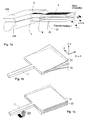
- the sensor consists of a tuning fork S with double tines Z1 and Z2, whose Base point, the base B, hangs on a torsion bar T, which in turn opens in a massive support structure, the upper wafer OW and the lower wafer UW is formed.
- a torsion bar T On the upper teeth Z1 of the Tuning fork S is an actuator layer or an actuator element A for tine excitation applied.
- the torsion bar T carries a sensitive layer S for signal detection, i.e. for torsion measurement.
- the basic prerequisite for the utilization of the Coriolis effect is the excitation of a tuning fork vibration.
- the corresponding excitation or tuning fork mode is shown schematically in Fig.lb.
- Bringing the thus oscillating sensor in a system that rotates about the longitudinal axis of the torsion bar (x-axis) with a rotational speed ⁇ so acts due to the antiphase oscillation of the prongs Z1 and Z2, which is perpendicular to the wafer surface (xy plane) , a torque D about the x-axis on the structure.
- This periodic torque leads to a torsional vibration of the torsion bar T.
- the corresponding torsional or readout mode is shown in Fig. 1c.
- the amplitude of the torsional vibration is directly proportional to the rate of rotation to be measured and the speed v of the tines.
- first embodiment will be described in two variants.
- the two variants differ in that in the first variant A is the thickness of the tuning fork suspension equal to the thickness of the tuning fork structure is. ( Figures 1-4).
- the thickness of the tuning fork suspension is smaller as the thickness of the tuning fork structure, i.
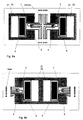
- the tuning fork (sensor middle part) consists of two Si wafers.
- the assembly is stacked of base and top wafers (of silicon and / or glass) and bonded to the central part so that the sensor cavity can be evacuated (Figure 4).
- the bonding frame is electrically tunnelled through a suitable doping profile in the bonding frame region in a vacuum-tight manner (FIG. 4).
- the excitation of a zinc is carried out via a piezoelectric thin film A, for example, AIN, ZnO 2 , PZT or the like. (Fig.1-4).
- the piezoelectric thin film A is contacted at the bottom via doped silicon (FIG. 4) or an electrically conductive thin film, at the top via an electrically conductive thin film.
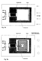
- the reading of the shear stress on the surface of the torsion bar T (or the suspension of the tuning fork) is piezoresistive; For this purpose, a four-sided contacting of the piezoresistor is necessary (Fig.3). Overall, the system operates as a resonant actuator-sensor system ( Figure 1).
- the starting material is two silicon wafers with buried thin films if necessary used for an etch stop when wet chemical, anisotropic Etching are suitable.
- monocrystalline silicon possibly also Poly-silicon
- SOI monocrystalline silicon
- doping types and doping concentrations preferably (100) silicum
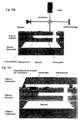
- Fig. 6 shows a block diagram of a proposed according to the invention Selection principle for the combination of piezoelectric excitation and the piezoresistive readout.
- the phase difference between current and voltage must be with compensated self-capacitance and stray capacitance of the piezoelectric Layer be equal to 0 °.
- This may e.g. by a phase comparator with Frequency tracking of a voltage controlled oscillator (VCO) achieved become.
- VCO voltage controlled oscillator
- a second possibility consists in the circuit in the feedback branch in a vibratory system. The amplitude stability of Prongs Z1 and Z2 are adjusted by tracking the piezo voltage ensures the piezoelectric current.
- the output signal of the piezoresistive sensor will after a preamp and a bandpass filtering with the order 90 ° out of phase excitation signal of the tines multiplied.
- the multiplier is a low-pass band limiting device downstream. If necessary, it is possible to use the sensor as a tethered Version interpreted. This can increase sensitivity and resolution become.
- the silicon wafers used can also be supplemented by epitaxial growth of silicon.
- the specified materials can also buried p / n transitions for the 'electrochemical etch stop' are used;
- wing structures or booms for targeted damping or for electrostatic excitation / readout can be used as e.g. in Fig.10a is shown.
- the tines can also with a predetermined profile such.
- the cross section of the torsion bar T can, for example, as shown in FIG 7f shown to be formed as a hollow profile.
- the geometry, in particular the length, the tuning fork base can adapt to the given material properties be adjusted.
- a tuning fork tines can be used accordingly Figure 7c be provided with a mass M for later trimming.
- the mechanical crosstalk can be achieved by the appropriate placement of the piezoresistive Element on the torsion bar are minimized. Furthermore can by applying one or more piezoresistors, the the longitudinal or transverse PR effect for measuring the bending stress use in the suspension of the tuning fork, the mechanical crosstalk be measured.
- thermomechanical excitation via implanted resistors or thin film resistors is a magnetic excitation represented by a magnetostrictive thin film TbFe, SmFe, (TbDy) Fe.
- electrostatic excitation of Fig. 9c with excitation electrodes is possible.
- electromagnetic excitation e.g. via a conductor loop in the homogeneous magnetic field and in Fig. 9e e.g. over a coil in the Inhomogeneous magnetic field parallel to the tine movement reproduced.
- shape memory materials in an arrangement such as come to use according to Figure 9a.
- all of the actuator thin films used may be on one or the other be applied to both tines of the tuning fork.
- the readout can be optically, for example by a reflective Layer and beam deflection angle, or through a layer whose optical properties depend on the mechanical stress in the layer or by a layer which according to FIG. 10b is part of a Michelson interferometer is done.
- FIGS. 11 a-d Various integration variants are presented with reference to FIGS. 11 a-d.
- the sensor electronics or parts of the electronics on the Chip to be integrated with the rotation rate sensor.
- at least two yaw-rate sensors are provided for simultaneous purposes Integrated measurement of several components of angular velocity.
- a DRS 1 and at least an acceleration sensor (BS) integrated on the same chip are provided.
- the BS may be sensitive to the wafer level or perpendicular to the wafer plane be arranged.
- Such an integrated microsystem may e.g. in an anti-spinner system for measuring yaw rate and lateral acceleration be used.
- the microsystem consists of at least two DRSs and at least two acceleration sensors and the associated electronics for precise determination of the two components of angular velocity and the acceleration in wafer plane as well as the acceleration perpendicular to.
- the natural frequencies of the excitation and the readout mode is set to be outside of the field of application the sensor relevant interference spectrum are.
- a frequency-selective Measurement according to the Lockin principle, thus results in an increased Insensitivity to lateral acceleration.
Landscapes
- Engineering & Computer Science (AREA)
- Physics & Mathematics (AREA)
- General Physics & Mathematics (AREA)
- Radar, Positioning & Navigation (AREA)
- Remote Sensing (AREA)
- Signal Processing (AREA)
- Gyroscopes (AREA)
- Pressure Sensors (AREA)
Abstract
Description
- Fig. 1a-c
- eine dreidimensionale Darstellung des ersten Ausführungsbeispiels,
und zwar
- a) die Prinzipdarstellung
- b) die Darstellung der Anregungsmode und
- c) die Darstellung der Auslesungs- oder Torsionsmode
- Fig. 2
- eine schematische Darstellung des Querschnitts des ersten Ausführungsbeispiels in der Variante A
- Fig.3
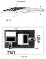
- eine schematische Aufsicht auf den Gegenstand der Erfindung,
- Fig.4
- einen schematischen Querschnitt A-A' durch den Gegenstand von Fig. 3,
- Fig.5
- schematisch den Querschnitt des ersten Ausführungsbeispiels in der Variante B
- Fig.6
- ein Blockschaltbild zur Auswertung des ersten Ausführungsbeispiels
- Fig. 7 a-c
- Konstruktive Varianten für die Geometrie zur Optimierung der Abstimmung
und zwar
- a) U-Profil
- b) Hohlprofil des Torsionsbalkens
- c) Zinken mit Trimmasse
- Fig. 8 a-b
- Varianten für die Bildung von Differenzsignalen und zwar
- a) entgegengesetzte Anordnung in zwei Ätzgruben und
- b) entgegengesetzte Anordnung in einer Ätzgrube
- Fig. 9. a-e:
- Varianten für die Anregung, und zwar
- a) Thermomechanisch (Formgedächtnis: analoger Aufbau),
- b) Magnetostriktiv,
- c) Elektrostatisch,
- d) Elektromagnetisch im homogenen B-Feld und
- e) Elektromagnetisch im inhomogenen B-Feld
- Fig. 10 a-c
- Varianten für den Auslesemechanismus, und zwar
- a) Elektrostatisch,
- b) Optisch (Interferometer) und
- c) Piezoelektrisch.
- Fig. 11 a-d
- Varianten für die monolithische Integration (insb. DRS und BS
mit der empfindlichen Richtung senkrecht zur Waferoberfläche)
und zwar
- a) Drehratensensor mit Signverarbeitungselektronik,
- b) zwei Drehratensensoren für unterschiedliche Achsen,
- c) ein Drehratensensor und ein Beschleunigungssensor und
- d) zwei Drehratensensoren und zwei Beschleunigungssensoren.
Claims (24)
- Mikromechanischer Drehratensensor, bei dem Teile aus Silizium, Siliziumverbindungen oder Silizium/Glasverbindungen oder anderen Halbleitermaterialien mit Techniken der Mikromechanik herausstrukturiert sind, dadurch gekennzeichnet,daß der Drehratensensor die Form einer Stimmgabel (S) aufweist, die an Halbleiterwafern (OW, UW) durch eine Stimmgabelaufhängung befestigt ist, wobei Zinken (Z1, Z2) der Stimmgabel (S) in Ebenen parallel zu der Oberfläche der Halbleiterwafer (OW, UW) liegen,daß diese Zinken (Z1, Z2) in einer Ebene senkrecht zur Waferebene zu Schwingungen anregbar sind, unddaß er ein Sensorelement (S) aufweist, das die Winkelgeschwindigkeit einer Drehung des Sensors um eine zur Stimmgabelaufhängung parallele Achse mißt.
- Drehratensensor nach Anspruch 1, dadurch gekennzeichnet, daß das Sensorelement die Torsion der Stimmgabelaufhängung registriert.
- Drehratensensor nach Anspruch 2, dadurch gekennzeichnet, daß das Sensorelement aus einkristallinem Si hergestellt ist.
- Drehratensensor nach Anspruch 2, dadurch gekennzeichnet, daß das Sensorelement aus anderen mikromechanisch strukturierbaren Materialien wie z.B.: Poly-Si, SiC, Siliziumnitrid, Siliziumdioxid, GaAs, Quarz, AlN, PZT oder Metallen besteht.
- Drehratensensor nach Anspruch 3 oder 4, dadurch gekennzeichnet, daß die Stimmgabel aus zwei Silizium-Wafern ggf. mit vergrabenen Dünnschichten besteht, die zwischen einem Basis- und einem Deckwafer liegen und daß die Teile so gebondet sind, daß die die Stimmgabel umgebende Kavität evakuierbar ist.
- Drehratensensor nach einem der vorhergehenden Ansprüche, dadurch gekennzeichnet, daß die Anregung eines Zinkens der Stimmgabel über eine piezoelektrische Dünnschicht und die Auslesung der Schubspannung des Torsionsbalkens piezoresistiv erfolgt.
- Drehratensensor nach einem der vorhergehenden Ansprüche, dadurch gekennzeichnet, daß der Querschnitt des Torsionsbalkens (T) als Hohlprofil ausgebildet ist.
- Drehratensensor nach einem der vorhergehenden Ansprüche, dadurch gekennzeichnet, daß der Querschnitt wenigstens eines Zinkens (Z1) ein U-förmiges Profil aufweist.
- Drehratensensor nach einem der vorhergehenden Ansprüche, dadurch gekennzeichnet, daß wenigstens ein Zinken (Z1) mit einer Trimmasse versehen ist.
- Drehratensensor nach einem der vorhergehenden Ansprüche, dadurch gekennzeichnet, daß die Anregung eines Zinkens der Stimmgabel thermomechanisch über implantierte Heizwiderstände oder Dünnschichtheizwiderstände erfolgt.
- Drehratensensor nach einem der vorhergehenden Ansprüche, dadurch gekennzeichnet, daß die Anregung eines Zinkens der Stimmgabel magnetisch über eine magnetostriktive Dünnschicht erfolgt.
- Drehratensensor nach einem der vorhergehenden Ansprüche, dadurch gekennzeichnet, daß die Anregung eines Zinkens der Stimmgabel elektrostatisch mit Hilfe von Anregungselektroden erfolgt.
- Drehratensensor nach einem der vorhergehenden Ansprüche, dadurch gekennzeichnet, daß die Anregung eines Zinkens der Stimmgabel elektromagnetisch über eine Leiterschleife in einem Magnetfeld erfolgt.
- Drehratensensor nach einem der vorhergehenden Ansprüche, dadurch gekennzeichnet, daß die Auslesung der Schubspannung des Torsionsbalkens elektrostatisch erfolgt.
- Drehratensensor nach einem der vorhergehenden Ansprüche, dadurch gekennzeichnet, daß die Auslesung der Schubspannung des Torsionsbalkens optisch über eine reflektierende Schicht und Ablenkung eines Strahls erfolgt.
- Drehratensensor nach Anspruch 15, dadurch gekennzeichnet, daß die reflektierende Schicht Bestandteil eines Interferometers ist.
- Drehratensensor nach einem der vorhergehenden Ansprüche, dadurch gekennzeichnet, daß die Auslesung der Schubspannung des Torsionsbalkens piezoelektrisch erfolgt.
- Drehratensensor nach einem der vorhergehenden Ansprüche, dadurch gekennzeichnet, daß wenigstens Teile der Ansteuer- oder Ausleseelektronik auf dem Chip mit dem Drehratensensor integriert sind.
- Drehratensensor nach einem der vorhergehenden Ansprüche, dadurch gekennzeichnet, daß er mit wenigstens einem weiteren Drehratensensor auf einem Chip integriert ist.
- Drehratensensor nach einem der vorhergehenden Ansprüche, dadurch gekennzeichnet, daß er mit wenigstens einem Beschleunigungssensor (BS) auf einem Chip integriert ist.
- Drehratensensor nach einem der vorhergehenden Ansprüche, dadurch gekennzeichnet, daß er mit wenigstens einem Beschleunigungssensor (BS) und einem Drehratensensor (DRS) auf einem Chip integriert ist.
- Drehratensensor nach einem der vorhergehenden Ansprüche, dadurch gekennzeichnet, daß die Dicke der Stimmgabelaufhängung gleich der Dicke der Stimmgabel-Struktur ist.
- Drehratensensor nach einem der vorhergehenden Ansprüche, dadurch gekennzeichnet, daß die Dicke der Stimmgabelaufhängung kleiner als die Dicke der Stimmgabel-Struktur ist.
- Drehratensensor nach einem der vorhergehenden Ansprüche, dadurch gekennzeichnet, daß er bezüglich der Torsion als gefesselter Sensor ausgebildet ist.
Applications Claiming Priority (3)
| Application Number | Priority Date | Filing Date | Title |
|---|---|---|---|
| DE19528961 | 1995-08-08 | ||
| DE19528961A DE19528961C2 (de) | 1995-08-08 | 1995-08-08 | Mikromechanischer Drehratensensor (DRS) und Sensoranordnung |
| PCT/EP1996/003412 WO1997006412A1 (de) | 1995-08-08 | 1996-08-02 | Mikromechanischer drehratensensor (drs) |
Publications (2)
| Publication Number | Publication Date |
|---|---|
| EP0843809A1 EP0843809A1 (de) | 1998-05-27 |
| EP0843809B1 true EP0843809B1 (de) | 2003-02-12 |
Family
ID=7768880
Family Applications (1)
| Application Number | Title | Priority Date | Filing Date |
|---|---|---|---|
| EP96927661A Expired - Lifetime EP0843809B1 (de) | 1995-08-08 | 1996-08-02 | Mikromechanischer drehratensensor (drs) |
Country Status (6)
| Country | Link |
|---|---|
| US (1) | US6474162B1 (de) |
| EP (1) | EP0843809B1 (de) |
| JP (1) | JP3950925B2 (de) |
| DE (2) | DE19528961C2 (de) |
| ES (1) | ES2189879T3 (de) |
| WO (1) | WO1997006412A1 (de) |
Cited By (1)
| Publication number | Priority date | Publication date | Assignee | Title |
|---|---|---|---|---|
| CN102507980A (zh) * | 2011-11-02 | 2012-06-20 | 重庆理工大学 | 一种基于自谐振技术的硅微二维加速度传感器 |
Families Citing this family (30)
| Publication number | Priority date | Publication date | Assignee | Title |
|---|---|---|---|---|
| DE19528961C2 (de) | 1995-08-08 | 1998-10-29 | Daimler Benz Ag | Mikromechanischer Drehratensensor (DRS) und Sensoranordnung |
| DE19812773C2 (de) * | 1998-03-24 | 2002-11-14 | Conti Temic Microelectronic | Mikrosensor mit einer Resonatorstruktur |
| DE19831594C1 (de) * | 1998-07-14 | 2000-01-27 | Litef Gmbh | Mikromechanischer Drehratensensor mit Koppelstruktur |
| DE19834535C1 (de) * | 1998-07-31 | 2000-03-16 | Daimler Chrysler Ag | Mikromechanischer Drehratensensor |
| DE19844686A1 (de) | 1998-09-29 | 2000-04-06 | Fraunhofer Ges Forschung | Mikromechanischer Drehratensensor und Verfahren zur Herstellung |
| DE19845185B4 (de) * | 1998-10-01 | 2005-05-04 | Eads Deutschland Gmbh | Sensor mit Resonanzstruktur sowie Vorrichtung und Verfahren zum Selbsttest eines derartigen Sensors |
| AUPQ081599A0 (en) * | 1999-06-08 | 1999-06-24 | Harris, Martin | Electrically operated tuning forks with novel geometry |
| RU2244936C2 (ru) * | 1999-11-30 | 2005-01-20 | Некрасов Яков Анатольевич | Устройство стабилизации температуры микромеханического чувствительного элемента |
| DE10007868B4 (de) * | 2000-02-21 | 2010-02-18 | Robert Bosch Gmbh | Elektronische Steuerschaltung |
| DE10010975B4 (de) * | 2000-03-07 | 2010-04-08 | Robert Bosch Gmbh | Mikromechanisches Bauelement |
| WO2001087767A2 (en) * | 2000-05-18 | 2001-11-22 | Stefaan De Schrijver | Micro-electrocmechamical sensor (mems) resonator |
| DE10139443A1 (de) * | 2001-08-10 | 2003-03-06 | Eads Deutschland Gmbh | Verfahren und Vorrichtung zum Trimmen von Sensoren mit schwingenden Strukturen |
| US6925413B2 (en) | 2001-12-14 | 2005-08-02 | Robert Bosch Gmbh | Method and system for detecting a spatial movement state of moving objects |
| DE10254163A1 (de) * | 2002-11-21 | 2004-06-03 | Eads Deutschland Gmbh | Mikromechanischer Drehratensensor |
| JP2005098841A (ja) * | 2003-09-25 | 2005-04-14 | Nippon Dempa Kogyo Co Ltd | 音叉型水晶振動子、角速度センサ素子、角速度センサ及び音叉型水晶振動子の製造方法。 |
| DE10349014B4 (de) * | 2003-10-17 | 2014-01-09 | Austriamicrosystems Ag | Mikroelektromechanischer Drehratensensor |
| DE102005045378A1 (de) * | 2005-09-22 | 2007-03-29 | Eads Deutschland Gmbh | Drehratensensor |
| DE102005045379A1 (de) * | 2005-09-22 | 2007-03-29 | Eads Deutschland Gmbh | Drehratensensor |
| JP2007248328A (ja) | 2006-03-17 | 2007-09-27 | Matsushita Electric Ind Co Ltd | 複合センサ |
| DE102006029443B3 (de) * | 2006-06-21 | 2008-01-31 | Siemens Ag | Sensor in mikromechanischer Bauweise zum Messen des Massendurchflusses nach dem Coriolis-Prinzip |
| US7808061B2 (en) * | 2006-07-28 | 2010-10-05 | Hewlett-Packard Development Company, L.P. | Multi-die apparatus including moveable portions |
| DE102007018834A1 (de) | 2007-04-20 | 2008-10-23 | Eads Deutschland Gmbh | Drehratensensor |
| GB2450157B (en) * | 2007-06-15 | 2011-12-21 | Baker Hughes Inc | System for determining an initial direction of rotation of an electrical submersible pump |
| DE102010018048A1 (de) | 2010-04-23 | 2011-10-27 | Northrop Grumman Litef Gmbh | Drehratensensor-Anordnung und Verfahren zum Betrieb einer Drehratensensor-Anordnung |
| JP5752803B2 (ja) * | 2010-12-23 | 2015-07-22 | クゥアルコム・テクノロジーズ・インコーポレイテッド | Rf装置およびrf装置のチューニング方法 |
| US9021887B2 (en) * | 2011-12-19 | 2015-05-05 | Infineon Technologies Ag | Micromechanical semiconductor sensing device |
| US8991250B2 (en) * | 2012-09-11 | 2015-03-31 | The United States Of America As Represented By Secretary Of The Navy | Tuning fork gyroscope time domain inertial sensor |
| DE102018213513B4 (de) * | 2018-08-10 | 2024-03-21 | Zf Friedrichshafen Ag | Fahrwerkbauteil, Verfahren zur Herstellung eines Fahrwerkbauteils sowie Radaufhängung für ein Kraftfahrzeug |
| US11060868B2 (en) * | 2019-04-09 | 2021-07-13 | United States Of America, As Represented By The Secretary Of The Navy | Weak value amplification Coriolis vibratory gyroscope |
| CN119533756B (zh) * | 2024-11-18 | 2025-10-21 | 中电科芯片技术(集团)有限公司 | 一种低温漂mems谐振压力传感器敏感芯片及其制备方法 |
Family Cites Families (31)
| Publication number | Priority date | Publication date | Assignee | Title |
|---|---|---|---|---|
| US3017775A (en) | 1958-03-27 | 1962-01-23 | Honeywell Regulator Co | Oscillatory inertial reference |
| US3218850A (en) * | 1962-08-14 | 1965-11-23 | Vernon L Rogallo | Thermo-protective device for balances |
| US3258617A (en) | 1963-02-07 | 1966-06-28 | Avco Corp | Piezoelectric device |
| SU534694A1 (ru) | 1975-04-14 | 1976-11-05 | Московское Ордена Ленина И Ордена Трудового Красного Знамени Высшее Техническое Училище Им.Н.Э.Баумана | Акселерометр |
| US4317126A (en) | 1980-04-14 | 1982-02-23 | Motorola, Inc. | Silicon pressure sensor |
| US4381672A (en) * | 1981-03-04 | 1983-05-03 | The Bendix Corporation | Vibrating beam rotation sensor |
| US4429248A (en) * | 1981-05-27 | 1984-01-31 | Statek Corporation | Mounting apparatus and method for piezoelectric tuning fork |
| US4489609A (en) | 1981-12-08 | 1984-12-25 | National Research Development Corporation | Gyroscopes |
| JPS60113105A (ja) | 1983-11-25 | 1985-06-19 | Yokogawa Hokushin Electric Corp | 振動式角速度計 |
| GB2158579B (en) * | 1984-01-23 | 1988-07-13 | Piezoelectric Technology Inves | Angular rate sensor system |
| US4598585A (en) * | 1984-03-19 | 1986-07-08 | The Charles Stark Draper Laboratory, Inc. | Planar inertial sensor |
| GB8408659D0 (en) | 1984-04-04 | 1984-05-16 | Syrinx Precision Instr Ltd | Rotation rate sensor |
| JPS6293668A (ja) * | 1985-10-21 | 1987-04-30 | Hitachi Ltd | 角速度・加速度検出器 |
| US4742260A (en) * | 1986-02-06 | 1988-05-03 | Hiroshi Shimizu | Piezoelectrically driving device |
| GB2208318B (en) * | 1987-07-24 | 1991-11-06 | Yazaki Corp | Vibrational angular velocity sensor |
| JPH02218914A (ja) | 1989-02-18 | 1990-08-31 | Nec Home Electron Ltd | 振動ジャイロ |
| US4889590A (en) | 1989-04-27 | 1989-12-26 | Motorola Inc. | Semiconductor pressure sensor means and method |
| DE4022495A1 (de) * | 1990-07-14 | 1992-01-23 | Bosch Gmbh Robert | Mikromechanischer drehratensensor |
| DE4041582A1 (de) * | 1990-12-22 | 1992-06-25 | Bosch Gmbh Robert | Drehratensensor |
| US5331853A (en) * | 1991-02-08 | 1994-07-26 | Alliedsignal Inc. | Micromachined rate and acceleration sensor |
| JP2992660B2 (ja) * | 1991-06-19 | 1999-12-20 | 本田技研工業株式会社 | ガスレートセンサ |
| DE69227910T2 (de) * | 1991-08-29 | 1999-05-12 | Bei Electronics, Inc., Sylmar, Calif. | Drehmessfühler |
| US5331852A (en) * | 1991-09-11 | 1994-07-26 | The Charles Stark Draper Laboratory, Inc. | Electromagnetic rebalanced micromechanical transducer |
| GB9207148D0 (en) * | 1992-04-01 | 1992-05-13 | British Aerospace | Planar rate sensor |
| JPH05333038A (ja) * | 1992-06-03 | 1993-12-17 | Canon Inc | 角速度センサ |
| GB9212099D0 (en) * | 1992-06-06 | 1992-07-22 | Lucas Ind Plc | Angular rate sensor and method of production thereof |
| DE4228795C2 (de) * | 1992-08-29 | 2003-07-31 | Bosch Gmbh Robert | Drehratensensor und Verfahren zur Herstellung |
| US5802684A (en) * | 1993-09-14 | 1998-09-08 | Nikon Corporation | Process for producing a vibration angular-velocity sensor |
| US5488862A (en) | 1993-10-18 | 1996-02-06 | Armand P. Neukermans | Monolithic silicon rate-gyro with integrated sensors |
| US5629790A (en) | 1993-10-18 | 1997-05-13 | Neukermans; Armand P. | Micromachined torsional scanner |
| DE19528961C2 (de) | 1995-08-08 | 1998-10-29 | Daimler Benz Ag | Mikromechanischer Drehratensensor (DRS) und Sensoranordnung |
-
1995
- 1995-08-08 DE DE19528961A patent/DE19528961C2/de not_active Expired - Fee Related
-
1996
- 1996-08-02 US US09/011,233 patent/US6474162B1/en not_active Expired - Fee Related
- 1996-08-02 JP JP50811297A patent/JP3950925B2/ja not_active Expired - Fee Related
- 1996-08-02 DE DE59610132T patent/DE59610132D1/de not_active Expired - Fee Related
- 1996-08-02 ES ES96927661T patent/ES2189879T3/es not_active Expired - Lifetime
- 1996-08-02 WO PCT/EP1996/003412 patent/WO1997006412A1/de not_active Ceased
- 1996-08-02 EP EP96927661A patent/EP0843809B1/de not_active Expired - Lifetime
Cited By (2)
| Publication number | Priority date | Publication date | Assignee | Title |
|---|---|---|---|---|
| CN102507980A (zh) * | 2011-11-02 | 2012-06-20 | 重庆理工大学 | 一种基于自谐振技术的硅微二维加速度传感器 |
| CN102507980B (zh) * | 2011-11-02 | 2013-11-27 | 重庆理工大学 | 一种基于自谐振技术的硅微二维加速度传感器 |
Also Published As
| Publication number | Publication date |
|---|---|
| DE59610132D1 (de) | 2003-03-20 |
| EP0843809A1 (de) | 1998-05-27 |
| US6474162B1 (en) | 2002-11-05 |
| JPH11510895A (ja) | 1999-09-21 |
| DE19528961A1 (de) | 1997-02-13 |
| ES2189879T3 (es) | 2003-07-16 |
| JP3950925B2 (ja) | 2007-08-01 |
| WO1997006412A1 (de) | 1997-02-20 |
| DE19528961C2 (de) | 1998-10-29 |
Similar Documents
| Publication | Publication Date | Title |
|---|---|---|
| EP0843809B1 (de) | Mikromechanischer drehratensensor (drs) | |
| EP1099094B1 (de) | Mikromechanischer drehratensensor und verfahren zur herstellung | |
| DE69731742T2 (de) | Aus silizium in mikrotechnologie hergestellter symmetrischer vibrationskreiselsensor | |
| DE4032559C2 (de) | Drehratensensor und Verfahren zur Herstellung | |
| DE102007017209B4 (de) | Mikromechanischer Inertialsensor zur Messung von Drehraten | |
| DE69328500T2 (de) | In konstantem elektrischen feldangetriebener schwingungswandler mit mikromechanischem balken | |
| EP0906557B1 (de) | Drehratensensor mit entkoppelten orthogonalen primär- und sekundärschwingungen | |
| DE69527714T2 (de) | Drehgeschwindigkeitskreiselsensor aus monolithischem silizium mit integrierten sensoren | |
| DE69735759T2 (de) | Mikrogefertigter vibrationsdrehgeschwindigkeitskreisel | |
| DE102010000818B4 (de) | MEMS-Resonatorbauelemente | |
| DE3719037A1 (de) | Vibrierender beschleunigungsmesser-multisensor | |
| DE69306314T2 (de) | Winkelgeschwindigkeitsmessaufnehmer sowie Methode zu seiner Herstellung | |
| DE69924235T2 (de) | Anordnung zur messung der winkelgeschwindigkeit | |
| WO2006034706A1 (de) | Drehratensensor | |
| DE10001361B4 (de) | Verfahren zum Herstellen eines Mikroträgheitssensors | |
| DE10040537B4 (de) | Mikromechanischer Drehratensensor und Verfahren zu seiner Herstellung | |
| DE69610013T2 (de) | Kraftmessaufnehmer | |
| DE60037312T2 (de) | Schwingbalken-kraftaufnehmer | |
| Nonomura et al. | SOI rate gyro sensor for automotive control | |
| DE69320977T2 (de) | Ferroelektrischer dünnfilm-wanderwellen-umdrehungssensor | |
| EP2153170B1 (de) | Drehratensensor | |
| DE10349014B4 (de) | Mikroelektromechanischer Drehratensensor | |
| DE4336004C2 (de) | Schwingungsgyroskop | |
| DE102005045379A1 (de) | Drehratensensor |
Legal Events
| Date | Code | Title | Description |
|---|---|---|---|
| PUAI | Public reference made under article 153(3) epc to a published international application that has entered the european phase |
Free format text: ORIGINAL CODE: 0009012 |
|
| 17P | Request for examination filed |
Effective date: 19980203 |
|
| AK | Designated contracting states |
Kind code of ref document: A1 Designated state(s): DE ES FR GB IT SE |
|
| RAP1 | Party data changed (applicant data changed or rights of an application transferred) |
Owner name: DAIMLERCHRYSLER AG |
|
| RAP1 | Party data changed (applicant data changed or rights of an application transferred) |
Owner name: EADS DEUTSCHLAND GMBH |
|
| 17Q | First examination report despatched |
Effective date: 20010801 |
|
| GRAH | Despatch of communication of intention to grant a patent |
Free format text: ORIGINAL CODE: EPIDOS IGRA |
|
| GRAH | Despatch of communication of intention to grant a patent |
Free format text: ORIGINAL CODE: EPIDOS IGRA |
|
| RAP1 | Party data changed (applicant data changed or rights of an application transferred) |
Owner name: EADS DEUTSCHLAND GMBH |
|
| GRAA | (expected) grant |
Free format text: ORIGINAL CODE: 0009210 |
|
| AK | Designated contracting states |
Designated state(s): DE ES FR GB IT SE |
|
| REG | Reference to a national code |
Ref country code: GB Ref legal event code: FG4D Free format text: NOT ENGLISH |
|
| REF | Corresponds to: |
Ref document number: 59610132 Country of ref document: DE Date of ref document: 20030320 Kind code of ref document: P |
|
| REG | Reference to a national code |
Ref country code: SE Ref legal event code: TRGR |
|
| GBT | Gb: translation of ep patent filed (gb section 77(6)(a)/1977) | ||
| REG | Reference to a national code |
Ref country code: ES Ref legal event code: FG2A Ref document number: 2189879 Country of ref document: ES Kind code of ref document: T3 |
|
| ET | Fr: translation filed | ||
| PLBE | No opposition filed within time limit |
Free format text: ORIGINAL CODE: 0009261 |
|
| STAA | Information on the status of an ep patent application or granted ep patent |
Free format text: STATUS: NO OPPOSITION FILED WITHIN TIME LIMIT |
|
| 26N | No opposition filed |
Effective date: 20031113 |
|
| PGFP | Annual fee paid to national office [announced via postgrant information from national office to epo] |
Ref country code: DE Payment date: 20060816 Year of fee payment: 11 |
|
| PGFP | Annual fee paid to national office [announced via postgrant information from national office to epo] |
Ref country code: FR Payment date: 20060817 Year of fee payment: 11 |
|
| PGFP | Annual fee paid to national office [announced via postgrant information from national office to epo] |
Ref country code: GB Payment date: 20060824 Year of fee payment: 11 |
|
| PGFP | Annual fee paid to national office [announced via postgrant information from national office to epo] |
Ref country code: ES Payment date: 20060830 Year of fee payment: 11 |
|
| PGFP | Annual fee paid to national office [announced via postgrant information from national office to epo] |
Ref country code: IT Payment date: 20060831 Year of fee payment: 11 |
|
| PGFP | Annual fee paid to national office [announced via postgrant information from national office to epo] |
Ref country code: SE Payment date: 20060814 Year of fee payment: 11 |
|
| EUG | Se: european patent has lapsed | ||
| GBPC | Gb: european patent ceased through non-payment of renewal fee |
Effective date: 20070802 |
|
| PG25 | Lapsed in a contracting state [announced via postgrant information from national office to epo] |
Ref country code: SE Free format text: LAPSE BECAUSE OF NON-PAYMENT OF DUE FEES Effective date: 20070803 |
|
| REG | Reference to a national code |
Ref country code: FR Ref legal event code: ST Effective date: 20080430 |
|
| PG25 | Lapsed in a contracting state [announced via postgrant information from national office to epo] |
Ref country code: DE Free format text: LAPSE BECAUSE OF NON-PAYMENT OF DUE FEES Effective date: 20080301 |
|
| PG25 | Lapsed in a contracting state [announced via postgrant information from national office to epo] |
Ref country code: FR Free format text: LAPSE BECAUSE OF NON-PAYMENT OF DUE FEES Effective date: 20070831 |
|
| REG | Reference to a national code |
Ref country code: ES Ref legal event code: FD2A Effective date: 20070803 |
|
| PG25 | Lapsed in a contracting state [announced via postgrant information from national office to epo] |
Ref country code: GB Free format text: LAPSE BECAUSE OF NON-PAYMENT OF DUE FEES Effective date: 20070802 |
|
| PG25 | Lapsed in a contracting state [announced via postgrant information from national office to epo] |
Ref country code: ES Free format text: LAPSE BECAUSE OF NON-PAYMENT OF DUE FEES Effective date: 20070803 |
|
| PG25 | Lapsed in a contracting state [announced via postgrant information from national office to epo] |
Ref country code: IT Free format text: LAPSE BECAUSE OF NON-PAYMENT OF DUE FEES Effective date: 20070802 |