EP0844007A2 - Distributeur de produit - Google Patents
Distributeur de produit Download PDFInfo
- Publication number
- EP0844007A2 EP0844007A2 EP97118019A EP97118019A EP0844007A2 EP 0844007 A2 EP0844007 A2 EP 0844007A2 EP 97118019 A EP97118019 A EP 97118019A EP 97118019 A EP97118019 A EP 97118019A EP 0844007 A2 EP0844007 A2 EP 0844007A2
- Authority
- EP
- European Patent Office
- Prior art keywords
- template
- storage space
- flow
- dispenser according
- medium
- Prior art date
- Legal status (The legal status is an assumption and is not a legal conclusion. Google has not performed a legal analysis and makes no representation as to the accuracy of the status listed.)
- Withdrawn
Links
- 239000002775 capsule Substances 0.000 claims description 11
- 230000007704 transition Effects 0.000 claims description 9
- 239000012530 fluid Substances 0.000 claims description 8
- 238000011144 upstream manufacturing Methods 0.000 claims description 7
- 239000011248 coating agent Substances 0.000 claims description 5
- 238000000576 coating method Methods 0.000 claims description 5
- 239000000843 powder Substances 0.000 claims description 3
- 230000006378 damage Effects 0.000 claims description 2
- 230000015572 biosynthetic process Effects 0.000 claims 1
- 239000003795 chemical substances by application Substances 0.000 claims 1
- 239000010419 fine particle Substances 0.000 claims 1
- 230000000149 penetrating effect Effects 0.000 claims 1
- 230000029058 respiratory gaseous exchange Effects 0.000 claims 1
- 230000000630 rising effect Effects 0.000 claims 1
- 239000002245 particle Substances 0.000 description 7
- 230000001154 acute effect Effects 0.000 description 2
- 210000003811 finger Anatomy 0.000 description 2
- 230000009969 flowable effect Effects 0.000 description 2
- 239000002184 metal Substances 0.000 description 2
- 210000003800 pharynx Anatomy 0.000 description 2
- 230000001681 protective effect Effects 0.000 description 2
- 210000003813 thumb Anatomy 0.000 description 2
- 108010010803 Gelatin Proteins 0.000 description 1
- 238000004026 adhesive bonding Methods 0.000 description 1
- 238000000889 atomisation Methods 0.000 description 1
- 230000005465 channeling Effects 0.000 description 1
- 239000000356 contaminant Substances 0.000 description 1
- 230000003247 decreasing effect Effects 0.000 description 1
- 230000001419 dependent effect Effects 0.000 description 1
- 230000000694 effects Effects 0.000 description 1
- 229920000159 gelatin Polymers 0.000 description 1
- 239000008273 gelatin Substances 0.000 description 1
- 235000019322 gelatine Nutrition 0.000 description 1
- 235000011852 gelatine desserts Nutrition 0.000 description 1
- 238000001746 injection moulding Methods 0.000 description 1
- 238000003780 insertion Methods 0.000 description 1
- 230000037431 insertion Effects 0.000 description 1
- 239000007788 liquid Substances 0.000 description 1
- 210000004072 lung Anatomy 0.000 description 1
- 238000004519 manufacturing process Methods 0.000 description 1
- 238000010137 moulding (plastic) Methods 0.000 description 1
- 238000010422 painting Methods 0.000 description 1
- 235000011837 pasties Nutrition 0.000 description 1
- 230000002093 peripheral effect Effects 0.000 description 1
- 238000007639 printing Methods 0.000 description 1
- 230000000241 respiratory effect Effects 0.000 description 1
- BFKJFAAPBSQJPD-UHFFFAOYSA-N tetrafluoroethene Chemical group FC(F)=C(F)F BFKJFAAPBSQJPD-UHFFFAOYSA-N 0.000 description 1
Images
Classifications
-
- A—HUMAN NECESSITIES
- A61—MEDICAL OR VETERINARY SCIENCE; HYGIENE
- A61M—DEVICES FOR INTRODUCING MEDIA INTO, OR ONTO, THE BODY; DEVICES FOR TRANSDUCING BODY MEDIA OR FOR TAKING MEDIA FROM THE BODY; DEVICES FOR PRODUCING OR ENDING SLEEP OR STUPOR
- A61M15/00—Inhalators
- A61M15/0028—Inhalators using prepacked dosages, one for each application, e.g. capsules to be perforated or broken-up
-
- A—HUMAN NECESSITIES
- A61—MEDICAL OR VETERINARY SCIENCE; HYGIENE
- A61M—DEVICES FOR INTRODUCING MEDIA INTO, OR ONTO, THE BODY; DEVICES FOR TRANSDUCING BODY MEDIA OR FOR TAKING MEDIA FROM THE BODY; DEVICES FOR PRODUCING OR ENDING SLEEP OR STUPOR
- A61M15/00—Inhalators
- A61M15/0001—Details of inhalators; Constructional features thereof
- A61M15/0013—Details of inhalators; Constructional features thereof with inhalation check valves
- A61M15/0016—Details of inhalators; Constructional features thereof with inhalation check valves located downstream of the dispenser, i.e. traversed by the product
-
- A—HUMAN NECESSITIES
- A61—MEDICAL OR VETERINARY SCIENCE; HYGIENE
- A61M—DEVICES FOR INTRODUCING MEDIA INTO, OR ONTO, THE BODY; DEVICES FOR TRANSDUCING BODY MEDIA OR FOR TAKING MEDIA FROM THE BODY; DEVICES FOR PRODUCING OR ENDING SLEEP OR STUPOR
- A61M15/00—Inhalators
- A61M15/0028—Inhalators using prepacked dosages, one for each application, e.g. capsules to be perforated or broken-up
- A61M15/003—Inhalators using prepacked dosages, one for each application, e.g. capsules to be perforated or broken-up using capsules, e.g. to be perforated or broken-up
- A61M15/0033—Details of the piercing or cutting means
- A61M15/0035—Piercing means
-
- A—HUMAN NECESSITIES
- A61—MEDICAL OR VETERINARY SCIENCE; HYGIENE
- A61M—DEVICES FOR INTRODUCING MEDIA INTO, OR ONTO, THE BODY; DEVICES FOR TRANSDUCING BODY MEDIA OR FOR TAKING MEDIA FROM THE BODY; DEVICES FOR PRODUCING OR ENDING SLEEP OR STUPOR
- A61M15/00—Inhalators
- A61M15/0028—Inhalators using prepacked dosages, one for each application, e.g. capsules to be perforated or broken-up
- A61M15/0045—Inhalators using prepacked dosages, one for each application, e.g. capsules to be perforated or broken-up using multiple prepacked dosages on a same carrier, e.g. blisters
- A61M15/0046—Inhalators using prepacked dosages, one for each application, e.g. capsules to be perforated or broken-up using multiple prepacked dosages on a same carrier, e.g. blisters characterized by the type of carrier
- A61M15/0048—Inhalators using prepacked dosages, one for each application, e.g. capsules to be perforated or broken-up using multiple prepacked dosages on a same carrier, e.g. blisters characterized by the type of carrier the dosages being arranged in a plane, e.g. on diskettes
-
- A—HUMAN NECESSITIES
- A61—MEDICAL OR VETERINARY SCIENCE; HYGIENE
- A61M—DEVICES FOR INTRODUCING MEDIA INTO, OR ONTO, THE BODY; DEVICES FOR TRANSDUCING BODY MEDIA OR FOR TAKING MEDIA FROM THE BODY; DEVICES FOR PRODUCING OR ENDING SLEEP OR STUPOR
- A61M2202/00—Special media to be introduced, removed or treated
- A61M2202/06—Solids
- A61M2202/064—Powder
-
- A—HUMAN NECESSITIES
- A61—MEDICAL OR VETERINARY SCIENCE; HYGIENE
- A61M—DEVICES FOR INTRODUCING MEDIA INTO, OR ONTO, THE BODY; DEVICES FOR TRANSDUCING BODY MEDIA OR FOR TAKING MEDIA FROM THE BODY; DEVICES FOR PRODUCING OR ENDING SLEEP OR STUPOR
- A61M2202/00—Special media to be introduced, removed or treated
- A61M2202/06—Solids
- A61M2202/064—Powder
- A61M2202/066—Powder made from a compacted product by abrading
-
- A—HUMAN NECESSITIES
- A61—MEDICAL OR VETERINARY SCIENCE; HYGIENE
- A61M—DEVICES FOR INTRODUCING MEDIA INTO, OR ONTO, THE BODY; DEVICES FOR TRANSDUCING BODY MEDIA OR FOR TAKING MEDIA FROM THE BODY; DEVICES FOR PRODUCING OR ENDING SLEEP OR STUPOR
- A61M2205/00—General characteristics of the apparatus
- A61M2205/02—General characteristics of the apparatus characterised by a particular materials
- A61M2205/0233—Conductive materials, e.g. antistatic coatings for spark prevention
-
- A—HUMAN NECESSITIES
- A61—MEDICAL OR VETERINARY SCIENCE; HYGIENE
- A61M—DEVICES FOR INTRODUCING MEDIA INTO, OR ONTO, THE BODY; DEVICES FOR TRANSDUCING BODY MEDIA OR FOR TAKING MEDIA FROM THE BODY; DEVICES FOR PRODUCING OR ENDING SLEEP OR STUPOR
- A61M2205/00—General characteristics of the apparatus
- A61M2205/07—General characteristics of the apparatus having air pumping means
- A61M2205/071—General characteristics of the apparatus having air pumping means hand operated
- A61M2205/073—Syringe, piston type
Definitions
- the invention relates to a dispenser for media which are gaseous, can be liquid, pasty and / or powdery. Of the It is advisable to carry the dispenser freely with one hand and to operate with this hand at the same time. Essentially all parts, especially housing parts, can consist of plastic or injection molding, so that their Wall thickness is not more than 5 mm or 2 mm.
- the Medium should in particular be finely distributed in a fluid stream, conveyed like a gas or air and as precisely as possible dosed single quanta and for this within the Device sufficiently swirled by multiple deflection will.
- the donor is to inhale a pharmaceutical Serve medium, it is expedient the flow only admixed during use, taking it beforehand is compressed much more compactly.
- the invention has for its object to a donor create the disadvantages of known training avoided or advantages of the type mentioned are to be achieved and which in particular is a precisely dosed, deep inside End of a patient's airway insertion Medium in finest atomization with ergonomically cheaper Handling guaranteed.
- means are provided to keep the medium inside to open up the donor's funding channels very finely, for example, by only one or more reciprocating Movement of the medium. So you can use existing ones larger particles into smaller particles on at least two opposing baffles are separated. in the In the case of a powder, this can be with or without airflow from the Storage first down into a trough-shaped baffle or Guide surface. After that it gets through the air flow lifted off this first surface at high speed, swirled and hurled against an opposite wall. This leads to a crushing of the possibly clumped Powder particles.
- the proportion of respiratory, i.e. particles that penetrate into the patient's lungs thereby significantly increased compared to such donors, which only for nasal application or for application of the medium in the pharynx are provided.
- the said first or another surface can also be used as Buffer or template for at least part of the Single application dose of the medium can be provided. At least part of this dose of the flowable medium falls then during the opening and if necessary afterwards on the template that is expanded upwards in a channel shape. With that only afterwards starting flow rate, this medium is from the template lifted off with swirling. Immediately afterwards it will be against hurled the wall above and against it again deflected in the direction of the fall towards the outlet or mouthpiece.
- the memory outlet and the template Divider can be another between the memory outlet and the template Divider provided for fanning out the media flow be, for example, a mandrel or a point. This serves also to open the memory. The tip extends into the Storage space or the medium contained therein.
- the conveyor path between the storage and the is advantageous Outlet at which the medium is completely detached emerges from the donor into the open, as short as possible.
- From the The swirl zone is the conveying path as straight as possible or only angled or curved at an obtuse angle. This results in low flow losses.
- the first way between the storage outlet and the swirl zone shorter than the second flow path between the middle of this Swirl zone and the outlet.
- the second way is at most four or three times longer than the first way.
- the middle the swirl zone can be with the center of the opposite Impact surface collapse.
- the smallest passage cross section the funding path is advantageously smaller than that of the continuous constant passage cross section of the storage space and is advantageously due to the transition. This is considered the closest Place from the two opposite surfaces limited.
- the straight end channel forms the outlet with one end.
- This and the end channel are at an angle to the storage or main axis of the device. This can therefore at oral application with head slightly tilted back be held vertically. The operator's thumb then lies between the upper lip and mouthpiece and can both are created.
- a pressure-dependent opening valve is provided from the storage space be. Only after reaching a predetermined negative pressure downstream of the valve, the flow is through the Valve opening started suddenly. Surrender very high flow rates.
- the valve can be a Be a cuff valve.
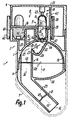
- the dispenser 1 has a base body 2 consisting of only five housing parts 3 to 7. Of these, on standby or Operating state only three firmly connected parts 3, 4, 6 together with a magazine unit 8 the entire Outer surface of the discharge device 1. Part 5 is complete sunk stuck in part 3 and through the part 4 immediately axially secured.
- the unit 8 has at least four and a maximum of eight evenly distributed and immediately adjacent to each other in a wreath by one Axis 10 arranged storage locations 9 for the medium.
- the Axis 10 is parallel to the main axis 11, in which the respective in the operating position 9 is. Right away from this position the 9th place for the discharge emptied through an outlet 12.
- Its axis 13 is below an obtuse angle of at least 110 ° and at most 160 °, in particular 135 °, to axis 10 or 11.
- the outlet 12 lies completely parallel to the axis 10, 11 within the outer circumference of the base body 2.
- the outlet 15 has one essential smaller distance from the upstream end of the Guide 14 as from its exit end 12.
- the outlet 15 is through one end of an elongated, separate storage body 16 formed with an elongated storage space 17. This is coaxial with the axis 11 in the emptying position.
- the rigid body 16 is in two parts Capsule made of hard gelatin or the like. Both of them sleeve-shaped Parts are closely matched axially.
- the capsule ends facing away from each other are hemispherical.
- the medium contained in room 17 is before opening packed tightly closed with a device 18.
- the non-gaseous, flowable medium completely fills the room 17 or only partially as a single dose.
- the body 16 or space 17 can only be closed by destruction to open. In operation, it forms one over its entire length reaching section of the guide 14.
- the on the two Openings lying at the ends of the room are essential in the manner of a throttle narrower than the part of the room 17 lying between the ends. This part has constant passage cross-sections throughout.
- the exposed one, formed only by parts 3, 4, 6, 8 Outer jacket 19 of device 1 can be operated with a single hand are almost completely enclosed.
- the guide 14 forms a zone 20 for swirling, Shredding and finely distributed processing of the Medium.
- the medium was already upstream of zone 20 absorbed by the air flow.
- Midway between the ends of the Guide 14 or the device 1 is in the operating position below the outlet 15 a bowl-shaped or trough-shaped Template 21 provided. It is only open at the top.
- your Bottom 24 has one of the length 15 of the outlet Room 17 smaller distance.
- the concave curved bottom 24 connects to a longer edge 22 and a shorter edge 23 on.
- the flanks 22, 23 diverge at an acute angle.
- the one between axes 10, 11, but closer to axis 10 lying common axial plane of the surfaces 22 to 24 or the The trough 21 is laterally opposite the axis 11 of the outlet 15 transferred.
- the outlet 15 is vertically above the center of the Bottom 24 when the device 1 is slightly in the operating position is tipped back.
- the axis 13 is flatter than slanted when the axes 10, 11 are aligned vertically is.
- the flank 22 connects to the outlet 15 in a sealed manner.
- the Flank 23 only extends to a narrow transition 25 between the trough 21 and the downstream thereof Part of the guide 14.
- the edge 23 extends to a rounded Edge 26 which is concave along its length.
- the edge 26 is opposite an overlying concave surface 27. It is like the trough 21 around one of the axes 10, 11 right-angled transverse axis curved. she has a compared to the bottom 24 at least four or five times larger Radius of curvature.
- the surface 27 extends in and against the flow direction about the crossing delimited by the edge 26 25 beyond.
- the area 27 extends to the outlet 15 and as Circumference limitation into a channel section 28. This closes downstream at the transition 25 and the edge 26 on.
- section 28 closes obtuse-angled at an end channel 29. Its end forms the outlet 12.
- the axis 30 of the section 28 lies parallel to axis 10, 11 and on the side away from axis 11 Side of the axis 10.
- the two channel sections 28, 29 are straightforward. You have constant throughout Passage cross sections which are larger than that of the crossing 25 are.
- Section 29 is characterized by a freely projecting, tubular connecting piece 31 of constant external cross sections educated.
- the mouthpiece 31 is over a largest Insert part of its length into the patient's mouth and to seal tightly with his lips.
- Section 29 can be slightly longer than section 28 to Edge 26. Trough 21 and nozzle 31 lie on the same Side of section 28.
- the trough 21 including the surfaces 22 to 24, 26 and a first longitudinal section of the channel part 28 is exclusive limited by part 5. This is against the direction of flow in part 3 until it stops inserted sunk and by the same in this direction inserted part 4 axially secured.
- Part 4 forms a longitudinal section adjoining part 3 of the channel part 28 and the section 29, the nozzle 31 and the outlet 12.
- Part 4 stands over the outer circumference of the Part 3 does not propose and strikes at its lower, more annular End face sealed with a ring shoulder.
- the Surface 27 extends over an arc angle of less than 90 ° and more than 45 °.
- the surface 27 is only through part 3 formed and continued continuously at both ends. So it forms an intermediate section of a semicircular or hemispherical or U-shaped inner surface of part 3. This inner surface has a continuation, which on the surface 27 adjoins.
- Part 5 lies with convex Surfaces close to this continuation. Following the Part 5 is part 4 with a peripheral surface close to the Continued on.
- the flank 22 extends up to these curved surfaces.
- the Surface 27 is in the area of the outlet 15 and in the connection to the flank 22 of a transition opening 46 for the Medium and the air flow penetrated.
- the opening 46 is in the axis 11.
- the passage cross section corresponds to the opening 46 the largest passage cross section of the room 17.
- Die The width of the transfer opening 46 is larger than the largest Width of the room 17.
- the trough 21 lies between the axes 11, 30.
- the largest width of the trough 21 is at the level of the edge 26 greater than the associated depth of this trough 21.
- Die Channel sections 21, 25, 28 point parallel to the plane of the drawing limits. They can be roughly flat as well be parallel to each other. Then the device is in the associated Area in web view in the form of a web. This area can be rotated like the surfaces mentioned, but also the axis 11 may be curved.
- the Part 4 of the body 2 a crowned handle 32.
- the other handle 33 is formed by the rear end of the body 2, namely through the outside of the end wall of part 6.
- the two Handle form a handle 32, 33.
- the thumb can on of the handle 32 and other fingers of the same hand can rest like a clamp on the handle 33 facing away from it.
- the mouthpiece 31 is between the lips introduced by the patient.
- the unit 8 has a magazine body which can be moved about the axis 10 34 on. This is fixed axially between the parts 3.6. It carries replaceable on its side facing part 6 a magazine insert 35 with the number mentioned the storage body 16.
- the body 34 has 9 for each place a holder 36, which projects freely in the direction of flow and is sleeve-shaped.
- the holder 36 encloses sealed as well as just one lower end of the body 16. By narrowing the jacket 36 forms a stop for the lower, curved end surface of the body 16.
- a corresponding bracket 37 only projects in the direction of flow. It is essential shorter than the bracket 36.
- Insert 35 a jacket 37 is provided.
- the cuff 37 engages a conical outer circumference in a conical inner surface on rear end of the bracket 36 a. So it is radial narrows close to the outer circumference of the narrower part of the body 16 on. Its extended cover part can with its end face rest on the upper end face of the insert disk 35. This protrudes this rear end or the cover part against the flow direction without contact into the interior of part 6.
- the lower longitudinal section of the capsule 16 lies completely in the brackets 36, 37 and penetrates the Body 34, 35. Like each of the other parts is 3 to 7, 35 the body 34 is formed in one piece. He points to the extreme Circumference of a jacket 38.
- the narrowed end is in the operating position or the outlet 15 of the holder 36 immediately adjacent to the transfer opening 46 in the surface 27 or to the outside the curved wall 47, which forms the surface 27.
- the body 34 lies completely on this outside. He is directly on part 3 with two concentric bearings 41, 42 rotatably mounted and axially in the opposite direction secured.
- the bearing parts are formed in one piece with part 3. They are made up of two interlocking bearing bodies for example, formed sleeves that are opposite to the flow direction protrude freely. They slide with their end faces Sleeves at the bottom of the wall 39.
- the outer sleeve of the outer bearing 41 slides with its outer circumference on the inner circumference of the jacket 38 and with its inner circumference on the outer circumferences of the brackets 36.
- the inner sleeve of the inner Bearing 42 also slides with its outer circumference to the External circumferences of the brackets 36, which together form one Form inner circumference.
- the opening lies between the two sleeves 46, which connects to the outlet 15.
- the two sleeves go in one piece into the curved wall of surface 27.
- the sleeve of the bearing 41 is eccentric to the axis 11 of the including adjacent housing part 3, 4 of the body 2 provided and stands on the side away from the handle 32 Page about parts 3, 4.
- a snap connection is provided be.
- Another radial and axial bearing is on the upper side the body 35, 39 provided.
- the jacket 43 slides Part 6 on this side on the inner circumference of the jacket 38 and on the upper end face of the body 35.
- the body 35 will kept in close contact with the top of wall 39.
- the jacket 43 also forms only over a partial circumference Outer jacket of part 6, since it is eccentric to this outer jacket lies. Outside of the bearing member 43, this engages Outer jacket stuck inside the jacket of part 3 a.
- the outer jacket is a resilient Snap lock secured against pulling off. By application however, it can counteract a correspondingly high pull-off force Flow direction can be replaced. After this peeling lies the body 35 with the bodies 16 freely accessible for replacement.
- the device 18 has two in the axis 11 and each other opposite opening members 44, 45. you are through Metal tips are formed and serve to break open the end walls the capsule 16 during the switching movement of the unit 8. The capsule 16 is thereby in the last phase of the transfer in the operating position of the members 44, 45 detected and shattered at the ends. Then the tips protrude into the room 17, each with a jagged opening is surrounded.
- the associated transition opening 46 of the curved Wall 47 is penetrated by link 44. It's on the wall 47 secured with the arms of a star-shaped bracket.
- the outer circumference of the tip 44 forms a guide surface. By they become the medium and the air flow in an envelope flow expanded.
- the rear tip 45 is on the inside of the End wall of part 3 attached.
- the tips 44, 45 are directed coaxially against each other.
- the ring 38 is with a Provide display device for its rotational position and snaps resilient in every operating position.
- the ring 38 is rotated until until the next capsule 16 lies in the axis 11 and then on is open at both ends. Part of it trickles when opened of the medium along the tip 44, then over a free fall and then along the flanks 22 and 23 to the ground 24 of the trough 21. Then the patient sucks on the mouthpiece 31. It is through openings in the housing space, which the upper end of the capsule 16 and the tip 45 receives from outside sucked in air. It flows through the upper opening of the Capsule 16 in room 17.
- the mixed medium then flows directly through the outlet 15 around the tip 44 into the opening 46. From this it flows against the Flank 22 closer to the outlet 12 deflected back upwards along the flank 22 and the bottom 24, tears off at the edge 26 and is immediately against the surface 27 passed.
- the flow rate takes this into account the trough 21 located medium. In the area of the trough 21 a roller flow can briefly arise. Through the The flow is accelerated by suction. The flow flows through the transition 25 into the channel 28, 29. There the flow is calmed down to the outlet 12 continues. When hitting the surface 27, opposite which the flank 23 lies on a radius beam larger media particles crushed by impact. For the next application will be the unit 8 by a place 9 turned on.
- the unit 8 is with a freewheel lock only rotatable in one direction.
- a sieve 48 or a filter is provided in the channel 28. It is inserted between parts 3, 4. This can possibly chipped particles of the capsule 16 or too large Media particles do not get into the patient's throat.
- a valve 49 may be provided downstream of the space 17. It opens depending on the pressure if a lower one downstream Pressure as upstream. The valve can increase with increasing Opening a constant or decreasing opening force exhibit. Then it opens suddenly after opening completely and the flow is released in pulses. The valve 49 returns to the closed position depending on the pressure. The valve 49 is close to the outlet 12 within the channel 29. This makes the upstream section the Guide 14 during the rest periods against the ingress of contaminants tightly closed.
- Part 7 is a protective cap educated. It becomes axially complete for use deducted. Part 7 takes the socket 31 in the protective position including opening 12 and the entire part 4 and the lower section of part 3 tightly closed.
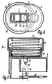
- Fig. 3 is only the upper portion of the dispenser from Part 6 shown.
- an air pump 50 is arranged at the top.
- the top end wall of the part 6 does not form a handle here, but detects one freely projecting jacket 52 on top.
- a cup-shaped Piston 41 with its jacket up to the stop on the End wall of part 6 inserted firmly.
- the extended Piston lip protrudes over the upper end of the jacket 52.
- the Piston lip slides on a cylinder 53. This surrounds the Outer circumference of the jacket 52 closely.
- the cylinder 53 can by Stop on the end wall of part 6 against the force of one Spring 54 to be moved down. This creates air through an opening 55 in the piston crown and in the end wall of the part 6 to the capsule 16 around the tip 45.
- the pump 50 lies in the axis 11.
- the end wall of the cylinder 53 forms the movable handle 33. After its release the pump returns to its starting position while drawing in fresh air back.
- the path through the opening 55 can a valve, for example valve 49, against suction be closed.
- the air flow can pass through Suction generated through opening 12 and to any Time can be increased by operating the pump 50.
- 3 is the insert 35 in its changing position for itself and shown without insert 34.
- the donor can be designed to scale according to Figures 1 to 3.
- the Boundary areas of the areas in contact with the medium come, especially in areas 12, 14, 18, 20 to 29, 44 to 46, 48 and 49, can be used with a non-stick or antistatic Coating made of metal and / or plastic, such as Tetrafluoroethylene. This can cause sticking of the medium by electrical charging or the like. avoided will.
- the coating is only a few ⁇ m thin. she can by painting, gluing, printing or the like. on the surfaces of the areas mentioned.
Landscapes
- Health & Medical Sciences (AREA)
- Engineering & Computer Science (AREA)
- Bioinformatics & Cheminformatics (AREA)
- Pulmonology (AREA)
- Anesthesiology (AREA)
- Biomedical Technology (AREA)
- Heart & Thoracic Surgery (AREA)
- Hematology (AREA)
- Life Sciences & Earth Sciences (AREA)
- Animal Behavior & Ethology (AREA)
- General Health & Medical Sciences (AREA)
- Public Health (AREA)
- Veterinary Medicine (AREA)
- Containers And Packaging Bodies Having A Special Means To Remove Contents (AREA)
- Medicinal Preparation (AREA)
- Nozzles (AREA)
- Dental Tools And Instruments Or Auxiliary Dental Instruments (AREA)
Applications Claiming Priority (2)
| Application Number | Priority Date | Filing Date | Title |
|---|---|---|---|
| DE19647947A DE19647947A1 (de) | 1996-11-20 | 1996-11-20 | Austragvorrichtung für Medien |
| DE19647947 | 1996-11-20 |
Publications (2)
| Publication Number | Publication Date |
|---|---|
| EP0844007A2 true EP0844007A2 (fr) | 1998-05-27 |
| EP0844007A3 EP0844007A3 (fr) | 1998-12-09 |
Family
ID=7812191
Family Applications (1)
| Application Number | Title | Priority Date | Filing Date |
|---|---|---|---|
| EP97118019A Withdrawn EP0844007A3 (fr) | 1996-11-20 | 1997-10-17 | Distributeur de produit |
Country Status (4)
| Country | Link |
|---|---|
| US (1) | US5964417A (fr) |
| EP (1) | EP0844007A3 (fr) |
| JP (1) | JPH10155907A (fr) |
| DE (1) | DE19647947A1 (fr) |
Cited By (30)
| Publication number | Priority date | Publication date | Assignee | Title |
|---|---|---|---|---|
| EP0950423A2 (fr) | 1998-04-18 | 1999-10-20 | Ing. Erich Pfeiffer GmbH | Distributeur de produit, en particulier pour une poudre |
| EP1466642A3 (fr) * | 1998-08-26 | 2005-11-30 | Bespak Plc | Dispositifs d'administration de médicaments |
| EP1649886A3 (fr) * | 1999-07-23 | 2006-07-19 | Mannkind Corporation | Capsules à dose unitaire pour un inhalateur à poudre sèche |
| EP1726323A3 (fr) * | 1999-12-17 | 2007-08-22 | Nektar Therapeutics | Recipients permettant l'extraction de poudres |
| US7464706B2 (en) | 1999-07-23 | 2008-12-16 | Mannkind Corporation | Unit dose cartridge and dry powder inhaler |
| US8146588B2 (en) | 1999-07-23 | 2012-04-03 | Mannkind Corporation | Unit dose capsules and dry powder inhaler |
| US9610351B2 (en) | 2011-10-24 | 2017-04-04 | Mannkind Corporation | Methods and compositions for treating pain |
| US9630930B2 (en) | 2009-06-12 | 2017-04-25 | Mannkind Corporation | Diketopiperazine microparticles with defined specific surface areas |
| US9700690B2 (en) | 2002-03-20 | 2017-07-11 | Mannkind Corporation | Inhalation apparatus |
| US9706944B2 (en) | 2009-11-03 | 2017-07-18 | Mannkind Corporation | Apparatus and method for simulating inhalation efforts |
| US9717689B2 (en) | 2005-09-14 | 2017-08-01 | Mannkind Corporation | Method of drug formulation based on increasing the affinity of crystalline microparticle surfaces for active agents |
| US9796688B2 (en) | 2004-08-20 | 2017-10-24 | Mannkind Corporation | Catalysis of diketopiperazine synthesis |
| US9801925B2 (en) | 1999-06-29 | 2017-10-31 | Mannkind Corporation | Potentiation of glucose elimination |
| US9802012B2 (en) | 2012-07-12 | 2017-10-31 | Mannkind Corporation | Dry powder drug delivery system and methods |
| US9925144B2 (en) | 2013-07-18 | 2018-03-27 | Mannkind Corporation | Heat-stable dry powder pharmaceutical compositions and methods |
| US9943571B2 (en) | 2008-08-11 | 2018-04-17 | Mannkind Corporation | Use of ultrarapid acting insulin |
| US9983108B2 (en) | 2009-03-11 | 2018-05-29 | Mannkind Corporation | Apparatus, system and method for measuring resistance of an inhaler |
| US10130709B2 (en) | 2011-06-17 | 2018-11-20 | Mannkind Corporation | High capacity diketopiperazine microparticles and methods |
| US10130581B2 (en) | 2006-02-22 | 2018-11-20 | Mannkind Corporation | Method for improving the pharmaceutic properties of microparticles comprising diketopiperazine and an active agent |
| US10130685B2 (en) | 2004-08-23 | 2018-11-20 | Mannkind Corporation | Diketopiperazine salts for drug delivery and related methods |
| US10159644B2 (en) | 2012-10-26 | 2018-12-25 | Mannkind Corporation | Inhalable vaccine compositions and methods |
| US10172850B2 (en) | 2008-12-29 | 2019-01-08 | Mannkind Corporation | Substituted diketopiperazine analogs for use as drug delivery agents |
| US10201672B2 (en) | 2008-06-13 | 2019-02-12 | Mannkind Corporation | Dry powder inhaler and system for drug delivery |
| US10307464B2 (en) | 2014-03-28 | 2019-06-04 | Mannkind Corporation | Use of ultrarapid acting insulin |
| US10342938B2 (en) | 2008-06-13 | 2019-07-09 | Mannkind Corporation | Dry powder drug delivery system |
| US10421729B2 (en) | 2013-03-15 | 2019-09-24 | Mannkind Corporation | Microcrystalline diketopiperazine compositions and methods |
| US10561806B2 (en) | 2014-10-02 | 2020-02-18 | Mannkind Corporation | Mouthpiece cover for an inhaler |
| US10625034B2 (en) | 2011-04-01 | 2020-04-21 | Mannkind Corporation | Blister package for pharmaceutical cartridges |
| US10675421B2 (en) | 2008-06-20 | 2020-06-09 | Mannkind Corporation | Interactive apparatus and method for real-time profiling of inhalation efforts |
| US11446127B2 (en) | 2013-08-05 | 2022-09-20 | Mannkind Corporation | Insufflation apparatus and methods |
Families Citing this family (50)
| Publication number | Priority date | Publication date | Assignee | Title |
|---|---|---|---|---|
| US6540154B1 (en) | 1991-04-24 | 2003-04-01 | Aerogen, Inc. | Systems and methods for controlling fluid feed to an aerosol generator |
| US7628339B2 (en) | 1991-04-24 | 2009-12-08 | Novartis Pharma Ag | Systems and methods for controlling fluid feed to an aerosol generator |
| US5758637A (en) | 1995-08-31 | 1998-06-02 | Aerogen, Inc. | Liquid dispensing apparatus and methods |
| US6085740A (en) | 1996-02-21 | 2000-07-11 | Aerogen, Inc. | Liquid dispensing apparatus and methods |
| ES2216418T3 (es) | 1995-12-07 | 2004-10-16 | Jago Research Ag | Boquilla para un inhalador para la administracion de varias dosis de un polvo seco farmacologico. |
| US7131441B1 (en) | 1995-12-07 | 2006-11-07 | Skyepharma Ag | Inhaler for multiple dosed administration of a pharmacological dry powder |
| DE19831525A1 (de) * | 1998-07-14 | 2000-01-20 | Pfeiffer Erich Gmbh & Co Kg | Spender für Medien |
| DE29908593U1 (de) | 1999-05-14 | 1999-07-22 | Jago Research AG, Hergiswil | Mundstück für einen Inhalator zur Abgabe eines Medikaments |
| DE19942791A1 (de) | 1999-09-08 | 2001-03-15 | Pfeiffer Erich Gmbh & Co Kg | Spender für Medien |
| US6235177B1 (en) | 1999-09-09 | 2001-05-22 | Aerogen, Inc. | Method for the construction of an aperture plate for dispensing liquid droplets |
| DE19961300A1 (de) * | 1999-12-18 | 2001-06-21 | Asta Medica Ag | Vorratssystem für Arzneimittel in Pulverform und damit ausgestatteter Inhalator |
| DE10011120A1 (de) * | 2000-03-09 | 2001-09-13 | Pfeiffer Erich Gmbh & Co Kg | Spender für Medien |
| US7971588B2 (en) | 2000-05-05 | 2011-07-05 | Novartis Ag | Methods and systems for operating an aerosol generator |
| US7600511B2 (en) | 2001-11-01 | 2009-10-13 | Novartis Pharma Ag | Apparatus and methods for delivery of medicament to a respiratory system |
| US6948491B2 (en) | 2001-03-20 | 2005-09-27 | Aerogen, Inc. | Convertible fluid feed system with comformable reservoir and methods |
| US8336545B2 (en) | 2000-05-05 | 2012-12-25 | Novartis Pharma Ag | Methods and systems for operating an aerosol generator |
| MXPA02010884A (es) | 2000-05-05 | 2003-03-27 | Aerogen Ireland Ltd | Aparato y metodo para el suministro de medicamentos al sistema respiratorio. |
| US7100600B2 (en) | 2001-03-20 | 2006-09-05 | Aerogen, Inc. | Fluid filled ampoules and methods for their use in aerosolizers |
| US6732944B2 (en) | 2001-05-02 | 2004-05-11 | Aerogen, Inc. | Base isolated nebulizing device and methods |
| US7677467B2 (en) | 2002-01-07 | 2010-03-16 | Novartis Pharma Ag | Methods and devices for aerosolizing medicament |
| US7360536B2 (en) | 2002-01-07 | 2008-04-22 | Aerogen, Inc. | Devices and methods for nebulizing fluids for inhalation |
| WO2003059424A1 (fr) | 2002-01-15 | 2003-07-24 | Aerogen, Inc. | Procedes et systemes de fonctionnement d'un generateur d'aerosol |
| US7258118B2 (en) | 2002-01-24 | 2007-08-21 | Sofotec Gmbh & Co, Kg | Pharmaceutical powder cartridge, and inhaler equipped with same |
| ES2572770T3 (es) | 2002-05-20 | 2016-06-02 | Novartis Ag | Aparato para proporcionar pulverización para tratamiento médico y métodos |
| DE10245326A1 (de) * | 2002-09-27 | 2004-04-08 | Abb Patent Gmbh | Ultraschall-Stehwellen-Zerstäuberanordnung |
| DE10252437A1 (de) * | 2002-11-12 | 2004-05-27 | Abb Patent Gmbh | Ultraschall-Stehwellen-Zerstäuberanordnung |
| US8616195B2 (en) | 2003-07-18 | 2013-12-31 | Novartis Ag | Nebuliser for the production of aerosolized medication |
| DE10352277A1 (de) * | 2003-11-08 | 2005-06-02 | Boehringer Ingelheim Pharma Gmbh & Co. Kg | Pulverinhalator |
| US7658721B2 (en) | 2004-01-16 | 2010-02-09 | Biodel Inc. | Sublingual drug delivery device |
| US7267121B2 (en) | 2004-04-20 | 2007-09-11 | Aerogen, Inc. | Aerosol delivery apparatus and method for pressure-assisted breathing systems |
| US7946291B2 (en) | 2004-04-20 | 2011-05-24 | Novartis Ag | Ventilation systems and methods employing aerosol generators |
| US7290541B2 (en) | 2004-04-20 | 2007-11-06 | Aerogen, Inc. | Aerosol delivery apparatus and method for pressure-assisted breathing systems |
| CA2563365A1 (fr) * | 2004-04-23 | 2005-11-03 | Mystic Pharmaceuticals, Inc. | Systeme d'administration de medicament en doses unitaires multiples |
| AU2014253488A1 (en) * | 2004-09-15 | 2014-11-13 | Optinose As | Nasal delivery devices |
| GB0420513D0 (en) * | 2004-09-15 | 2004-10-20 | Optinose As | Powder delivery devices |
| PL370286A1 (pl) * | 2004-09-23 | 2006-04-03 | Glaxosmithkline Pharmaceuticals Spółka Akcyjna | Inhalator proszkowy - układ otwierania i opróżniania kapsułek |
| EP1896662B1 (fr) | 2005-05-25 | 2014-07-23 | AeroGen, Inc. | Systemes et procedes de vibrations |
| US20070212307A1 (en) * | 2006-02-10 | 2007-09-13 | Daniel Wermeling | Pharmaceutical Compositions Comprising an Opioid Receptor Antagonist and Methods of Using Same |
| GB0611659D0 (en) * | 2006-06-13 | 2006-07-19 | Cambridge Consultants | Dry powder inhalers |
| JP2010515541A (ja) | 2007-01-09 | 2010-05-13 | ミスティック ファーマシューティカルズ, インコーポレイテッド | 経鼻カートリッジデバイス |
| US8683995B2 (en) | 2007-05-16 | 2014-04-01 | Mystic Pharmaceuticals, Inc. | Dose dispensing containers |
| CA2688689C (fr) | 2007-05-16 | 2015-06-30 | Mystic Pharmaceuticals, Inc. | Contenants combines de distribution-dose unitaire |
| US9248076B2 (en) | 2007-05-16 | 2016-02-02 | Mystic Pharmaceuticals, Inc. | Dose dispensing containers |
| CA2699634C (fr) * | 2007-09-14 | 2015-06-09 | Mystic Pharmaceuticals, Inc. | Procede de faconnage d'un receptacle par emboutissage profond |
| US8056343B2 (en) * | 2008-10-01 | 2011-11-15 | General Electric Company | Off center combustor liner |
| IT1395945B1 (it) * | 2009-09-30 | 2012-11-02 | Oliva | Inalatore perfezionato per preparati in polvere |
| IL223742A (en) | 2010-06-21 | 2016-06-30 | Mannkind Corp | A dry powder inhaler and preparation for it |
| GB2544477A (en) * | 2015-11-16 | 2017-05-24 | 3M Innovative Properties Co | Improvements in or relating to medical actuators |
| US10933208B2 (en) * | 2016-11-14 | 2021-03-02 | Vandana M. Krishna | Asthma inhaler accessory |
| WO2022049087A1 (fr) * | 2020-09-01 | 2022-03-10 | Janssen Pharmaceutica Nv | Dispositifs d'administration de médicament avec multiples flacons de médicament |
Family Cites Families (23)
| Publication number | Priority date | Publication date | Assignee | Title |
|---|---|---|---|---|
| GB1118341A (en) * | 1965-04-20 | 1968-07-03 | Fisons Pharmaceuticals Ltd | Inhalation device |
| US3888252A (en) * | 1974-01-23 | 1975-06-10 | Anthony J Side | Powder inhaler |
| FR2352556A1 (fr) * | 1976-05-26 | 1977-12-23 | Pasteur Institut | Inhalateur de poudre |
| US4778054A (en) * | 1982-10-08 | 1988-10-18 | Glaxo Group Limited | Pack for administering medicaments to patients |
| GB2169265B (en) * | 1982-10-08 | 1987-08-12 | Glaxo Group Ltd | Pack for medicament |
| DE3811309C2 (de) * | 1988-04-02 | 1997-09-04 | Weitmann & Konrad Fa | Vorrichtung zum Zerstäuben von Puder |
| US5113855A (en) * | 1990-02-14 | 1992-05-19 | Newhouse Michael T | Powder inhaler |
| DE4004904A1 (de) * | 1990-02-16 | 1990-09-13 | Gerhard Brendel | Trommel-applikator |
| NZ250988A (en) * | 1990-06-14 | 1995-09-26 | Rhone Poulenc Rorer Ltd | Powder inhaler: swirling chamber with anti-static walls |
| DE4021263C2 (de) * | 1990-07-04 | 1996-04-11 | Pfeiffer Erich Gmbh & Co Kg | Austragvorrichtung für Medien |
| GB9015522D0 (en) * | 1990-07-13 | 1990-08-29 | Braithwaite Philip W | Inhaler |
| FR2667509B1 (fr) * | 1990-10-04 | 1995-08-25 | Valois | Inhalateur a poudre, dispositif de conditionnement de microdoses de poudre sous forme de bandes adaptees a etre utilisees dans un inhalateur a poudre, et procede de fabrication de ces bandes. |
| GB9027234D0 (en) * | 1990-12-15 | 1991-02-06 | Harris Pharma Ltd | An inhalation device |
| DE4128295A1 (de) * | 1991-08-27 | 1993-03-04 | Pfeiffer Erich Gmbh & Co Kg | Austragvorrichtung fuer fliessfaehige medien |
| DE4133281A1 (de) * | 1991-10-08 | 1993-04-15 | Kloeckner Humboldt Deutz Ag | Spruehvorrichtung zum aufbringen von antihaftmitteln auf die kontaktflaeche einer formplatte |
| DE4134665A1 (de) * | 1991-10-19 | 1993-04-22 | Solvay Deutschland | Medizinisches inhalationssystem |
| DE4208880A1 (de) * | 1992-03-19 | 1993-09-23 | Boehringer Ingelheim Kg | Separator fuer pulverinhalatoren |
| US5239993A (en) * | 1992-08-26 | 1993-08-31 | Glaxo Inc. | Dosage inhalator providing optimized compound inhalation trajectory |
| DE4306458C2 (de) * | 1993-03-02 | 1996-06-05 | Lindopharm Gmbh | Vernebler für medizinische Zwecke |
| SE9302550D0 (sv) * | 1993-07-30 | 1993-07-30 | Ernst Hoerlin | Powder inhaler |
| NL9400346A (nl) * | 1994-03-07 | 1995-10-02 | Itsac Nv | Vloeistofdispenser met navulverpakking. |
| DE4415462C1 (de) * | 1994-05-03 | 1995-08-31 | Transcoject Marketing Gmbh | Inhalator |
| GB2300371B (en) * | 1995-05-05 | 1997-08-06 | Andrew Ian Briggs | Particulate dispenser |
-
1996
- 1996-11-20 DE DE19647947A patent/DE19647947A1/de not_active Withdrawn
-
1997
- 1997-10-17 EP EP97118019A patent/EP0844007A3/fr not_active Withdrawn
- 1997-11-07 US US08/966,377 patent/US5964417A/en not_active Expired - Fee Related
- 1997-11-07 JP JP9320618A patent/JPH10155907A/ja active Pending
Cited By (37)
| Publication number | Priority date | Publication date | Assignee | Title |
|---|---|---|---|---|
| EP0950423A2 (fr) | 1998-04-18 | 1999-10-20 | Ing. Erich Pfeiffer GmbH | Distributeur de produit, en particulier pour une poudre |
| EP1466642A3 (fr) * | 1998-08-26 | 2005-11-30 | Bespak Plc | Dispositifs d'administration de médicaments |
| US9801925B2 (en) | 1999-06-29 | 2017-10-31 | Mannkind Corporation | Potentiation of glucose elimination |
| EP1649886A3 (fr) * | 1999-07-23 | 2006-07-19 | Mannkind Corporation | Capsules à dose unitaire pour un inhalateur à poudre sèche |
| US7464706B2 (en) | 1999-07-23 | 2008-12-16 | Mannkind Corporation | Unit dose cartridge and dry powder inhaler |
| US8146588B2 (en) | 1999-07-23 | 2012-04-03 | Mannkind Corporation | Unit dose capsules and dry powder inhaler |
| US8156936B2 (en) | 1999-07-23 | 2012-04-17 | Mannkind Corporation | Unit dose capsules and dry powder inhaler |
| US8215300B2 (en) | 1999-07-23 | 2012-07-10 | Mannkind Corporation | Unit dose cartridge and dry powder inhaler |
| US9061111B2 (en) | 1999-07-23 | 2015-06-23 | Mannkind Corporation | Unit dose capsules and dry powder inhaler |
| EP1726323A3 (fr) * | 1999-12-17 | 2007-08-22 | Nektar Therapeutics | Recipients permettant l'extraction de poudres |
| US9700690B2 (en) | 2002-03-20 | 2017-07-11 | Mannkind Corporation | Inhalation apparatus |
| US9796688B2 (en) | 2004-08-20 | 2017-10-24 | Mannkind Corporation | Catalysis of diketopiperazine synthesis |
| US10130685B2 (en) | 2004-08-23 | 2018-11-20 | Mannkind Corporation | Diketopiperazine salts for drug delivery and related methods |
| US9717689B2 (en) | 2005-09-14 | 2017-08-01 | Mannkind Corporation | Method of drug formulation based on increasing the affinity of crystalline microparticle surfaces for active agents |
| US10143655B2 (en) | 2005-09-14 | 2018-12-04 | Mannkind Corporation | Method of drug formulation |
| US10130581B2 (en) | 2006-02-22 | 2018-11-20 | Mannkind Corporation | Method for improving the pharmaceutic properties of microparticles comprising diketopiperazine and an active agent |
| US10342938B2 (en) | 2008-06-13 | 2019-07-09 | Mannkind Corporation | Dry powder drug delivery system |
| US10201672B2 (en) | 2008-06-13 | 2019-02-12 | Mannkind Corporation | Dry powder inhaler and system for drug delivery |
| US12447293B2 (en) | 2008-06-13 | 2025-10-21 | Mannkind Corporation | Dry powder inhaler and system for drug delivery |
| US10751488B2 (en) | 2008-06-13 | 2020-08-25 | Mannkind Corporation | Dry powder inhaler and system for drug delivery |
| US10675421B2 (en) | 2008-06-20 | 2020-06-09 | Mannkind Corporation | Interactive apparatus and method for real-time profiling of inhalation efforts |
| US9943571B2 (en) | 2008-08-11 | 2018-04-17 | Mannkind Corporation | Use of ultrarapid acting insulin |
| US10172850B2 (en) | 2008-12-29 | 2019-01-08 | Mannkind Corporation | Substituted diketopiperazine analogs for use as drug delivery agents |
| US9983108B2 (en) | 2009-03-11 | 2018-05-29 | Mannkind Corporation | Apparatus, system and method for measuring resistance of an inhaler |
| US9630930B2 (en) | 2009-06-12 | 2017-04-25 | Mannkind Corporation | Diketopiperazine microparticles with defined specific surface areas |
| US9706944B2 (en) | 2009-11-03 | 2017-07-18 | Mannkind Corporation | Apparatus and method for simulating inhalation efforts |
| US10625034B2 (en) | 2011-04-01 | 2020-04-21 | Mannkind Corporation | Blister package for pharmaceutical cartridges |
| US10130709B2 (en) | 2011-06-17 | 2018-11-20 | Mannkind Corporation | High capacity diketopiperazine microparticles and methods |
| US9610351B2 (en) | 2011-10-24 | 2017-04-04 | Mannkind Corporation | Methods and compositions for treating pain |
| US10258664B2 (en) | 2011-10-24 | 2019-04-16 | Mannkind Corporation | Methods and compositions for treating pain |
| US9802012B2 (en) | 2012-07-12 | 2017-10-31 | Mannkind Corporation | Dry powder drug delivery system and methods |
| US10159644B2 (en) | 2012-10-26 | 2018-12-25 | Mannkind Corporation | Inhalable vaccine compositions and methods |
| US10421729B2 (en) | 2013-03-15 | 2019-09-24 | Mannkind Corporation | Microcrystalline diketopiperazine compositions and methods |
| US9925144B2 (en) | 2013-07-18 | 2018-03-27 | Mannkind Corporation | Heat-stable dry powder pharmaceutical compositions and methods |
| US11446127B2 (en) | 2013-08-05 | 2022-09-20 | Mannkind Corporation | Insufflation apparatus and methods |
| US10307464B2 (en) | 2014-03-28 | 2019-06-04 | Mannkind Corporation | Use of ultrarapid acting insulin |
| US10561806B2 (en) | 2014-10-02 | 2020-02-18 | Mannkind Corporation | Mouthpiece cover for an inhaler |
Also Published As
| Publication number | Publication date |
|---|---|
| DE19647947A1 (de) | 1998-05-28 |
| US5964417A (en) | 1999-10-12 |
| EP0844007A3 (fr) | 1998-12-09 |
| JPH10155907A (ja) | 1998-06-16 |
Similar Documents
| Publication | Publication Date | Title |
|---|---|---|
| EP0844007A2 (fr) | Distributeur de produit | |
| EP0147755B1 (fr) | Inhalateur | |
| DE69528912T2 (de) | Inhalator | |
| DE69129188T2 (de) | Inhalator mit einem reservoir für mehrere dosierte inhalationsmittel, mit transportvorrichtung und mit wirbelkammer | |
| EP0957962B1 (fr) | Distributeur de substances | |
| EP1220700B1 (fr) | Inhalateur de respiration controlée pour poudre | |
| DE69723156T2 (de) | Inhalatoren mit reguliertem Durchfluss | |
| DE69515536T2 (de) | Vorrichtung zum Inhalieren von Pulverarzneimitteln | |
| EP0530625B1 (fr) | Distributeur de fluides | |
| DE69832679T2 (de) | Vorrichtung zur Verabreichung von einem Arzneimittel in Aerosolform | |
| DE69033607T2 (de) | Vorrichtung zum wirkungsvollen Zerstäuben eines pulverförmigen Medikaments zur Inhalation | |
| DE3429389C1 (de) | Inhalator | |
| DE69203541T2 (de) | Einblasgerät für Mehrfachdosierungen von pulverförmigen Medikamenten. | |
| DE68911003T2 (de) | Verteiler für eine pulverförmige Medikation. | |
| DE3786757T2 (de) | Inhalator. | |
| DE60027714T3 (de) | Zerstäubungssystem mit niedriger spraykraft und retention | |
| DE2600862A1 (de) | Inhalationseinrichtung | |
| DE2625925A1 (de) | Inhaliervorrichtung | |
| EP0661070A1 (fr) | Dispositif d'inhalation | |
| EP0923993A1 (fr) | Distributeur de fluide | |
| DE10007591A1 (de) | Medizinischer Vernebelungsapparat | |
| DE19502725A1 (de) | Austragvorrichtung für Medien | |
| DE4415462C1 (de) | Inhalator | |
| DE10258360A1 (de) | Pulverinhalator mit Kapselkammer zum Aufnehmen einer mit Wirkstoff gefüllten Einwegkapsel | |
| EP0782866B1 (fr) | Tête de diffuseur, en particulier pour le traitement médicamenteux de la gorge |
Legal Events
| Date | Code | Title | Description |
|---|---|---|---|
| PUAI | Public reference made under article 153(3) epc to a published international application that has entered the european phase |
Free format text: ORIGINAL CODE: 0009012 |
|
| AK | Designated contracting states |
Kind code of ref document: A2 Designated state(s): BE CH DE DK ES FI FR GB IT LI NL PT SE |
|
| PUAL | Search report despatched |
Free format text: ORIGINAL CODE: 0009013 |
|
| AK | Designated contracting states |
Kind code of ref document: A3 Designated state(s): AT BE CH DE DK ES FI FR GB GR IE IT LI LU MC NL PT SE |
|
| 17P | Request for examination filed |
Effective date: 19990205 |
|
| AKX | Designation fees paid |
Free format text: BE CH DE DK ES FI FR GB IT LI NL PT SE |
|
| 17Q | First examination report despatched |
Effective date: 20010509 |
|
| STAA | Information on the status of an ep patent application or granted ep patent |
Free format text: STATUS: THE APPLICATION HAS BEEN WITHDRAWN |
|
| 18W | Application withdrawn |
Withdrawal date: 20020305 |