EP0844092A2 - Calotte pour poste de nettoyage pour têtes d'imprimante à jet d'encre - Google Patents
Calotte pour poste de nettoyage pour têtes d'imprimante à jet d'encre Download PDFInfo
- Publication number
- EP0844092A2 EP0844092A2 EP97250341A EP97250341A EP0844092A2 EP 0844092 A2 EP0844092 A2 EP 0844092A2 EP 97250341 A EP97250341 A EP 97250341A EP 97250341 A EP97250341 A EP 97250341A EP 0844092 A2 EP0844092 A2 EP 0844092A2
- Authority
- EP
- European Patent Office
- Prior art keywords
- cap
- ink
- printhead
- cavity
- cap body
- Prior art date
- Legal status (The legal status is an assumption and is not a legal conclusion. Google has not performed a legal analysis and makes no representation as to the accuracy of the status listed.)
- Granted
Links
- 230000002093 peripheral effect Effects 0.000 claims description 9
- 239000002245 particle Substances 0.000 description 4
- 238000001035 drying Methods 0.000 description 3
- 230000002745 absorbent Effects 0.000 description 2
- 239000002250 absorbent Substances 0.000 description 2
- 244000043261 Hevea brasiliensis Species 0.000 description 1
- 230000006835 compression Effects 0.000 description 1
- 238000007906 compression Methods 0.000 description 1
- 230000003247 decreasing effect Effects 0.000 description 1
- 239000000428 dust Substances 0.000 description 1
- 239000000463 material Substances 0.000 description 1
- 229920003052 natural elastomer Polymers 0.000 description 1
- 229920001194 natural rubber Polymers 0.000 description 1
- 230000001681 protective effect Effects 0.000 description 1
- 238000007789 sealing Methods 0.000 description 1
- 229920003051 synthetic elastomer Polymers 0.000 description 1
- 239000005061 synthetic rubber Substances 0.000 description 1
- 238000013022 venting Methods 0.000 description 1
- 238000009736 wetting Methods 0.000 description 1
Images


Classifications
-
- B—PERFORMING OPERATIONS; TRANSPORTING
- B41—PRINTING; LINING MACHINES; TYPEWRITERS; STAMPS
- B41J—TYPEWRITERS; SELECTIVE PRINTING MECHANISMS, i.e. MECHANISMS PRINTING OTHERWISE THAN FROM A FORME; CORRECTION OF TYPOGRAPHICAL ERRORS
- B41J2/00—Typewriters or selective printing mechanisms characterised by the printing or marking process for which they are designed
- B41J2/005—Typewriters or selective printing mechanisms characterised by the printing or marking process for which they are designed characterised by bringing liquid or particles selectively into contact with a printing material
- B41J2/01—Ink jet
- B41J2/135—Nozzles
- B41J2/165—Prevention or detection of nozzle clogging, e.g. cleaning, capping or moistening for nozzles
- B41J2/16505—Caps, spittoons or covers for cleaning or preventing drying out
- B41J2/16508—Caps, spittoons or covers for cleaning or preventing drying out connected with the printer frame
Definitions
- the present invention relates to ink-jet printers and, more particularly, to a cap for a service station for servicing ink-jet printheads.
- Ink-jet printers print by shooting drops of ink onto a page.
- the ink is stored in a reservoir and discharged onto the page through nozzles in a printhead.
- the printhead moves back and forth across the page shooting drops as it moves.
- a problem with ink-jet printers is that air bubbles may be forced into the nozzles to interfere with the operation of the printhead. Additionally, ink may drool out of the nozzles, dry and clog them. Items such as dirt and paper dust may also collect on the printhead and clog the nozzles.
- ink-jet printers typically include caps and service stations.
- a cap encloses and defines a cavity around the printhead when the printhead is not in use or needs servicing.
- a service station is a location on the printer where the printhead can be serviced. The cap is usually located in the service station.
- the cap helps prevent ink from drying on the printhead by providing a cavity that is kept moist. Ink is discharged into the cavity and the moisture from the ink keeps it from drying on the printhead.
- the volume of the cavity is decreased when the cap encloses the printhead, resulting in a change of pressure within the cavity. If the pressure within the cavity changes, air bubbles are forced into the nozzles of the printhead. Thus, the caps are vented to allow the pressure within the cavity to equalize with the pressure outside the cavity so that air bubbles are not forced into the nozzle of the printhead.
- caps have been vented through a pump connected to the cavity.
- An example of such a cap is disclosed in U.S. Pat. No. 4,853,717 entitled “Service Station for Ink-Jet Printer. "
- a control algorithm causes printhead to fire ink through all the nozzles into cap to clean the nozzles and remove any plugs of ink.
- the nozzles may also be fired at selected times during printing. The drops of ink that are fired keep the cavity defined by the cap moist or in humid environment so that ink will not dry on the printhead when it is not in use.
- an elastic cap is placed over the nozzle end of a printhead to ensure a sufficiently humid environment.
- a cap must form a leak-free seal between the printhead nozzles and the ambient environment. Forcing the cap into the printhead with enough force to deform the cap around its sealing lip accomplishes this leak-free seal.
- An example of such an elastic cap is disclosed in U.S. Pat. No. 5,448,270 entitled “Ink-Jet Printhead Cap Having Suspended Lip.”
- a problem with ink-jet printhead caps is that humid environment within a cavity around the nozzles may be broken through vents that open directly to the cavity.
- vents may be covered with an absorbent pad to create an effective seal while insuring venting to the ambient environment, thereby preventing the cavity from being dried.
- An object of the present invention is to provide an effective seal between the cavity defined by a cap and the ambient environment without any absorbent pad.
- a cap defines a cavity around a printhead and a capillary space to create effective seal between the cavity and a vent associated with the cavity.
- an ink-jet printer comprising:
- a cap for an ink-jet printhead comprising:
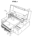
- Fig. 1 shows a typical ink-jet printer 10 with its lid 12 open and raised so that a printhead carriage 14 and printhead cartridge 16 are visible.
- Cartridge 16 is mounted on carriage 14 and they both move back and forth on rod 18 and guard 20.
- carriage 14 and cartridge 16 are shown at the extreme right end of rod 18, in the location of the service station.
- Cartridge 14 is moved to the service station when the printer is not printing or when it needs servicing. On other printers the service station may be located in the left end of rod 18.
- Printer 10 also includes an input paper tray 22 and an output paper tray 24. Paper enters the printer from tray 22, moves through the printer, and exits into tray 24. As the paper exists into tray 24, cartridge 16 moves back and forth across the sheet and discharges drops of ink, resulting in a printed image. In Fig. 1, a sheet of paper 26 is shown exiting the printer after printing.
- Cartridge 16 includes an ink reservoir (not shown) and a printhead 30 (see Fig. 4).
- printhead 30 includes nozzles (not shown) through which ink is discharged from the reservoir onto the paper.
- printhead 30 is shown enclosed by a protective cap 32 that defines a cavity around the printhead.
- the cavity is kept moist by drops of ink that have been discharged or drooled into the cavity from the printhead. Ink may be discharged from the printhead into the cavity to clear the nozzles from any plugs of ink or simply to keep the cavity moist. The moisture in the cavity helps prevent ink from drying on the printhead or clogging the nozzles.
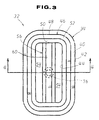
- Cap 32 is illustrated in detail in Figs. 2 through 5.
- Cap 32 in its preferred embodiment includes a cap body 34 and a basin structure 36.
- the cap body 34 includes base and top walls 38 and 40 that are spaced but interconnected by outer and inner peripheral walls 42 and 44.
- the cap body 34 also includes a lip region 46 protruding from the top wall 40. Lip region 46 extends around the periphery of the cap body. As may be seen in Figs. 3 and 4, lip region 46 is preferably peripherally coextensive with the top wall 40. Lip region 46 may be seen in Fig. 4 to include a vertical surface 48 and an outwardly inclined surface 50 that terminate in a top surface 52 that is dimensioned to provide an impact point for the generally planer ink-jet's printhead, thereby to sealingly engage it, as shown.
- Cap body 34 may be seen by reference to Figs. 1 and 3 to be annular.
- the inner peripheral wall 44 defines a hole 54 centrally located in the cap body.
- Cap body 34 also includes a beam 56 extending across hole 54.
- Beam 56 may be seen by reference to Fig. 4 to taper in cross section upwardly and inwardly to a point in what may be described as a generally trapezoidal configuration.
- beam 56 extends from one portion of inner peripheral wall 44 to the remotest opposite portion thereof, and has a base flat surface 58 that bridges base wall 38 and a top surface 60 that bridges top wall 40.
- base flat surface 58 extends coplanar with base flat wall 38.
- cap body 34 has a peripheral channel 62 dimensioned to receive an upwardly extending annular boss region or cap mount 64 of the basin structure 35 partly therein.
- channel 62 in cross section may be seen to have an upwardly and inwardly inclined exterior sidewall 70 and an upwardly and outwardly inclined interior sidewall 72.
- Inclined exterior and interior sidewalls 70 and 72 extend upwardly to a point in a generally triangular cross-sectional profile of channel 62.
- Cap mount 64 extends along the periphery of a relatively stiff frame member 66 of basin structure 36.
- Frame member 66 mounts cam mount 64 on its upper planar flat wall 68.
- Frame member 66 has a vent hole 74 extending downwardly, viewing in Fig.
- Vent hole 74 is centrally located and opposed to base surface 58 of the beam 56.
- Cap mount 64 tapers in cross section upwardly and inwardly substantially to a point in a generally triangular cross-sectional configuration.
- Channel 62 and cam mount 64 are dimensioned such that a predetermined clearance C is provided between base wall 38 of cap body 34 and upper planar flat wall 68 of frame member 66.
- a capillary space 78 is defined between base surface 58 ofbeam 56 and upper planar flat wall of the frame 66.
- Capillary space 78 extends completely along the periphery of vent port 76 so that the vent port communicates via the capillary space with hole 54.
- cap body 34 is constructed of a wetting material such as natural rubber or synthetic rubber.
- Vent hole 74 extends through a downwardly protruding boss 80. As seen in Fig. 4, vent hole 74 is connected via a tube 82 to a suction pump 84.
- cap 32 is moved against the printhead.
- cap body 34 engages, to form compression fit of lip region 46, with, printhead 30. This seals the cavity that is defined by the working surface of printhead 30, lip region 46, inner peripheral wall 44 of cap body 34, and the upper planar flat wall 68 of frame 66.
- pump 84 is put into operation, dried ink particles and bubbles are drawn from the nozzles of printhead 30 into the inside of the cavity defined by cap 32.
- the ink particles collected in the inside of cap body 34 are drawn into tube 82 past through capillary space 78 and the vent hole 74 toward suction pump 84.
- the ink particles are discharged into a reservoir, not shown, after leaving pump 84.
- ink particles Owing to capillary action, a portion of the ink particles remains in the capillary 78 to form ink film, providing effective seal between port 76 of vent hole 74 and the cavity defined by cap 32. This prevents the nozzles of printhead 30 from communicating with the ambient environment. Provision of the ink film in capillary space 78 not only seals the cavity defined by cap 32, but also keeps the cavity and the nozzles of printhead 30 humid.
- the present invention is embodied in a cap of the so-called temporary capping type wherein, when an ink-jet printhead needs servicing, an cap is moved against the printhead.
- the present invention may equally be embodied in a cap of the so-called permanent capping type.
Landscapes
- Ink Jet (AREA)
Applications Claiming Priority (3)
| Application Number | Priority Date | Filing Date | Title |
|---|---|---|---|
| JP8308568A JP2878214B2 (ja) | 1996-11-20 | 1996-11-20 | インクジェット記録装置 |
| JP30856896 | 1996-11-20 | ||
| JP308568/96 | 1996-11-20 |
Publications (3)
| Publication Number | Publication Date |
|---|---|
| EP0844092A2 true EP0844092A2 (fr) | 1998-05-27 |
| EP0844092A3 EP0844092A3 (fr) | 1998-08-26 |
| EP0844092B1 EP0844092B1 (fr) | 2002-04-03 |
Family
ID=17982597
Family Applications (1)
| Application Number | Title | Priority Date | Filing Date |
|---|---|---|---|
| EP97250341A Expired - Lifetime EP0844092B1 (fr) | 1996-11-20 | 1997-11-15 | Calotte pour poste de nettoyage pour têtes d'imprimante à jet d'encre |
Country Status (7)
| Country | Link |
|---|---|
| US (1) | US6068364A (fr) |
| EP (1) | EP0844092B1 (fr) |
| JP (1) | JP2878214B2 (fr) |
| CN (1) | CN1078538C (fr) |
| AU (1) | AU724168B2 (fr) |
| CA (1) | CA2221764A1 (fr) |
| DE (1) | DE69711552T2 (fr) |
Cited By (6)
| Publication number | Priority date | Publication date | Assignee | Title |
|---|---|---|---|---|
| EP1086815A1 (fr) * | 1999-09-27 | 2001-03-28 | Nec Corporation | Unité de nettoyage pour imprimante à jet d'encre capable d'aspirer suffisamment de l'encre perdu |
| EP1095774A1 (fr) * | 1999-10-29 | 2001-05-02 | Xerox Corporation | Ensemble de fermeture et d'amorçage à aération pour tête d'impression à jet d'encre |
| EP1106359A1 (fr) * | 1999-12-01 | 2001-06-13 | Seiko Epson Corporation | Apareil d'enregistrement à jet d'encre |
| DE10147999A1 (de) * | 2000-12-21 | 2002-07-11 | Acer Comm & Multimedia Inc | Tintenstrahlabdeckung mit Entlüftungsöffnung |
| US6517185B1 (en) | 2001-03-09 | 2003-02-11 | Lexmark International, Inc. | Low force ink jet printhead capping system |
| AU2004202887B2 (en) * | 2000-10-20 | 2005-10-06 | Zamtec Limited | Printhead nozzles using viscous drag |
Families Citing this family (23)
| Publication number | Priority date | Publication date | Assignee | Title |
|---|---|---|---|---|
| JP4630452B2 (ja) * | 2000-09-29 | 2011-02-09 | セイコーインスツル株式会社 | キャップ部材の製造方法 |
| JP2002326366A (ja) * | 2001-04-27 | 2002-11-12 | Canon Inc | インクジェット記録装置及び記録ヘッド用キャップ |
| US6905189B1 (en) | 2002-05-16 | 2005-06-14 | Vutek, Inc. | Wet capping tray for ink jet printheads |
| JP3991900B2 (ja) * | 2003-03-27 | 2007-10-17 | ブラザー工業株式会社 | 印刷ヘッド用キャップ |
| JP4343573B2 (ja) * | 2003-04-10 | 2009-10-14 | 芝浦メカトロニクス株式会社 | 塗布装置およびヘッドのクリーニング方法 |
| JP2005193568A (ja) * | 2004-01-08 | 2005-07-21 | Sony Corp | ノズルキャップ、ヘッドキャップユニット、及び液体吐出ヘッド |
| US7188925B2 (en) * | 2004-01-30 | 2007-03-13 | Hewlett-Packard Development Company, L.P. | Fluid ejection head assembly |
| CN100427312C (zh) * | 2004-05-20 | 2008-10-22 | 明基电通股份有限公司 | 事务机及其喷墨卡匣密闭装置 |
| JP4626264B2 (ja) * | 2004-10-28 | 2011-02-02 | ブラザー工業株式会社 | 記録ヘッドの保管装置および保管方法 |
| JP4728633B2 (ja) * | 2004-12-03 | 2011-07-20 | 株式会社東芝 | インクジェット塗布装置 |
| JP2006239936A (ja) * | 2005-03-01 | 2006-09-14 | Brother Ind Ltd | 画像形成装置およびキャップ |
| US7520588B2 (en) * | 2005-12-23 | 2009-04-21 | Xerox Corp | Apparatus for reducing ink jet contamination |
| JP2007261216A (ja) * | 2006-03-29 | 2007-10-11 | Seiko Epson Corp | アクチュエータ装置及び液体噴射ヘッド並びに液体噴射装置 |
| JP4895358B2 (ja) * | 2006-05-16 | 2012-03-14 | キヤノン株式会社 | インクジェット記録ヘッド |
| US7571996B2 (en) * | 2006-08-10 | 2009-08-11 | Xerox Corporation | Apparatus for reducing particulate in an ink jet printer |
| JP4241792B2 (ja) * | 2006-09-25 | 2009-03-18 | ブラザー工業株式会社 | キャップ及びインクジェット保護アセンブリ |
| CN101224666B (zh) * | 2007-11-23 | 2010-10-06 | 李支斌 | 喷墨打印机的墨栈结构 |
| WO2011136788A1 (fr) | 2010-04-30 | 2011-11-03 | Hewlett-Packard Development Company, L.P. | Obturation par capuchon pour imprimantes à jet d'encre |
| JP2012016852A (ja) * | 2010-07-07 | 2012-01-26 | Miyakoshi Printing Machinery Co Ltd | 吐出インク回収装置 |
| JP5598317B2 (ja) * | 2010-12-27 | 2014-10-01 | セイコーエプソン株式会社 | キャッピング装置、および液体噴射装置 |
| US9375933B2 (en) | 2014-03-17 | 2016-06-28 | Seiko Epson Corporation | Liquid ejecting apparatus |
| US10814632B2 (en) * | 2018-03-22 | 2020-10-27 | Kyocera Document Solutions Inc. | Cap member and ink-jet recording apparatus including same |
| CN108357210A (zh) * | 2018-04-19 | 2018-08-03 | 湖南长城信息金融设备有限责任公司 | 喷墨打印机构及其应用的票据处理设备 |
Family Cites Families (13)
| Publication number | Priority date | Publication date | Assignee | Title |
|---|---|---|---|---|
| JPS5945161A (ja) * | 1982-09-08 | 1984-03-13 | Seiko Epson Corp | インクジェットプリンタのノズル乾燥防止方法 |
| US4853717A (en) * | 1987-10-23 | 1989-08-01 | Hewlett-Packard Company | Service station for ink-jet printer |
| US5027134A (en) * | 1989-09-01 | 1991-06-25 | Hewlett-Packard Company | Non-clogging cap and service station for ink-jet printheads |
| DE59007404D1 (de) * | 1990-01-09 | 1994-11-10 | Eastman Kodak Co | Saug- und abdeckeinrichtung zum absaugen von tinte aus tintendruckköpfen eines tintendruckwerkes und zum abdecken der tintendruckköpfe. |
| JPH03213351A (ja) * | 1990-01-19 | 1991-09-18 | Canon Inc | 液体噴射記録装置 |
| US5717444A (en) * | 1990-04-11 | 1998-02-10 | Canon Kabushiki Kaisha | Suction recovery device and ink jet recording apparatus using the device |
| EP0670223B1 (fr) * | 1990-04-11 | 2000-07-12 | Canon Kabushiki Kaisha | Méthode de régénération à décharge pour une tête à jet d'encre et dispositif pour l'application de cette méthode |
| US5216449A (en) * | 1991-07-29 | 1993-06-01 | Hewlett-Packard Company | Rounded capillary vent system for ink-jet printers |
| US5146243A (en) * | 1991-07-29 | 1992-09-08 | Hewlett-Packard Company | Diaphragm cap system for ink-jet printers |
| US5210550A (en) * | 1991-12-23 | 1993-05-11 | Xerox Corporation | Maintenance station for ink jet printers |
| DE69307053T2 (de) * | 1992-08-26 | 1997-04-17 | Hewlett Packard Co | Abdeckung mit einer federnden Lippe für einen Tintenstrahl-Druckkopf |
| JP3155871B2 (ja) * | 1992-10-30 | 2001-04-16 | キヤノン株式会社 | インクジェット記録装置 |
| JPH06336029A (ja) * | 1993-05-28 | 1994-12-06 | Canon Inc | インクジェット記録装置 |
-
1996
- 1996-11-20 JP JP8308568A patent/JP2878214B2/ja not_active Expired - Fee Related
-
1997
- 1997-11-15 US US08/971,480 patent/US6068364A/en not_active Expired - Lifetime
- 1997-11-15 EP EP97250341A patent/EP0844092B1/fr not_active Expired - Lifetime
- 1997-11-15 DE DE69711552T patent/DE69711552T2/de not_active Expired - Lifetime
- 1997-11-19 AU AU45277/97A patent/AU724168B2/en not_active Expired
- 1997-11-19 CA CA002221764A patent/CA2221764A1/fr not_active Abandoned
- 1997-11-20 CN CN97121646A patent/CN1078538C/zh not_active Expired - Lifetime
Cited By (10)
| Publication number | Priority date | Publication date | Assignee | Title |
|---|---|---|---|---|
| EP1086815A1 (fr) * | 1999-09-27 | 2001-03-28 | Nec Corporation | Unité de nettoyage pour imprimante à jet d'encre capable d'aspirer suffisamment de l'encre perdu |
| US6491369B1 (en) | 1999-09-27 | 2002-12-10 | Nec Corporation | Head cleaning unit for ink-jet printer capable of sufficiently sucking up waste ink |
| EP1095774A1 (fr) * | 1999-10-29 | 2001-05-02 | Xerox Corporation | Ensemble de fermeture et d'amorçage à aération pour tête d'impression à jet d'encre |
| US6283576B1 (en) | 1999-10-29 | 2001-09-04 | Xerox Corporation | Ventable ink jet printhead capping and priming assembly |
| EP1106359A1 (fr) * | 1999-12-01 | 2001-06-13 | Seiko Epson Corporation | Apareil d'enregistrement à jet d'encre |
| US6491370B2 (en) | 1999-12-01 | 2002-12-10 | Seiko Epson Corporation | Ink jet recording apparatus |
| AU2004202887B2 (en) * | 2000-10-20 | 2005-10-06 | Zamtec Limited | Printhead nozzles using viscous drag |
| DE10147999A1 (de) * | 2000-12-21 | 2002-07-11 | Acer Comm & Multimedia Inc | Tintenstrahlabdeckung mit Entlüftungsöffnung |
| DE10147999B4 (de) * | 2000-12-21 | 2004-02-12 | Benq Corp., Kweishan | Tintenstrahlabdeckung mit Entlüftungsöffnung |
| US6517185B1 (en) | 2001-03-09 | 2003-02-11 | Lexmark International, Inc. | Low force ink jet printhead capping system |
Also Published As
| Publication number | Publication date |
|---|---|
| AU724168B2 (en) | 2000-09-14 |
| EP0844092B1 (fr) | 2002-04-03 |
| EP0844092A3 (fr) | 1998-08-26 |
| JPH10146986A (ja) | 1998-06-02 |
| DE69711552T2 (de) | 2003-04-03 |
| CA2221764A1 (fr) | 1998-05-20 |
| US6068364A (en) | 2000-05-30 |
| DE69711552D1 (de) | 2002-05-08 |
| CN1182678A (zh) | 1998-05-27 |
| AU4527797A (en) | 1998-05-28 |
| JP2878214B2 (ja) | 1999-04-05 |
| CN1078538C (zh) | 2002-01-30 |
Similar Documents
| Publication | Publication Date | Title |
|---|---|---|
| EP0844092B1 (fr) | Calotte pour poste de nettoyage pour têtes d'imprimante à jet d'encre | |
| US5027134A (en) | Non-clogging cap and service station for ink-jet printheads | |
| JP3985062B2 (ja) | 通気手段を有するインクジェットプリンタ用のカートリッジ | |
| US9630413B2 (en) | Liquid recovery containers and liquid ejection apparatus | |
| JP3228565B2 (ja) | インクジェットプリンタ用キャップシステム | |
| US5146243A (en) | Diaphragm cap system for ink-jet printers | |
| KR970007631B1 (ko) | 보관용기 | |
| ITTO950732A1 (it) | Stampante alimentata con inchiostro e serbatoio di alimentazione di inchiostro | |
| PT1600297E (pt) | Cartucho de tinta para utilização num aparelho de gravação de jacto de tinta | |
| US4456916A (en) | Ink jet cartridge with hydrostatic controller | |
| JP3164156B2 (ja) | 清掃及び密封装置を有するインキジェットプリンタ | |
| JP2007144634A (ja) | インクジェット記録装置 | |
| JP4013650B2 (ja) | 印刷装置 | |
| EP1504910A1 (fr) | Conduits d'air pour réservoir d'encre et procédé d'aération | |
| JP2003127400A (ja) | インクジェット式記録装置 | |
| US10471722B2 (en) | Waste liquid tank and printer | |
| JPH09123469A (ja) | インクジェットヘッド記録装置 | |
| EP0755794B1 (fr) | Structure de réservoir à encre | |
| JP2007090716A (ja) | 液体収容容器及び液体噴射装置 | |
| JP3899580B2 (ja) | インクジェットプリンタのインクカートリッジ | |
| JP4161538B2 (ja) | インクジェット式記録装置及びその非常用カートリッジ | |
| JPH0976529A (ja) | インクジェットプリンタのインク吸収装置 | |
| JPH0976531A (ja) | インクジェットプリンタのインク吸収装置 | |
| JPH0717048A (ja) | インクカートリッジ保管箱 | |
| US20070052749A1 (en) | Ink discharge device for preventing cap from clogging |
Legal Events
| Date | Code | Title | Description |
|---|---|---|---|
| PUAI | Public reference made under article 153(3) epc to a published international application that has entered the european phase |
Free format text: ORIGINAL CODE: 0009012 |
|
| AK | Designated contracting states |
Kind code of ref document: A2 Designated state(s): DE FR GB IT NL SE |
|
| AX | Request for extension of the european patent |
Free format text: AL;LT;LV;MK;RO;SI |
|
| PUAL | Search report despatched |
Free format text: ORIGINAL CODE: 0009013 |
|
| AK | Designated contracting states |
Kind code of ref document: A3 Designated state(s): AT BE CH DE DK ES FI FR GB GR IE IT LI LU MC NL PT SE |
|
| AX | Request for extension of the european patent |
Free format text: AL;LT;LV;MK;RO;SI |
|
| 17P | Request for examination filed |
Effective date: 19980910 |
|
| AKX | Designation fees paid |
Free format text: DE FR GB IT NL SE |
|
| RBV | Designated contracting states (corrected) |
Designated state(s): DE FR GB IT NL SE |
|
| 17Q | First examination report despatched |
Effective date: 19990819 |
|
| GRAG | Despatch of communication of intention to grant |
Free format text: ORIGINAL CODE: EPIDOS AGRA |
|
| GRAG | Despatch of communication of intention to grant |
Free format text: ORIGINAL CODE: EPIDOS AGRA |
|
| GRAH | Despatch of communication of intention to grant a patent |
Free format text: ORIGINAL CODE: EPIDOS IGRA |
|
| RIN1 | Information on inventor provided before grant (corrected) |
Inventor name: TANAKA, KOICHI Inventor name: KUSUMI, TATSUYA |
|
| REG | Reference to a national code |
Ref country code: GB Ref legal event code: IF02 |
|
| GRAH | Despatch of communication of intention to grant a patent |
Free format text: ORIGINAL CODE: EPIDOS IGRA |
|
| GRAA | (expected) grant |
Free format text: ORIGINAL CODE: 0009210 |
|
| AK | Designated contracting states |
Kind code of ref document: B1 Designated state(s): DE FR GB IT NL SE |
|
| REF | Corresponds to: |
Ref document number: 69711552 Country of ref document: DE Date of ref document: 20020508 |
|
| RAP2 | Party data changed (patent owner data changed or rights of a patent transferred) |
Owner name: FUJI XEROX CO., LTD. |
|
| REG | Reference to a national code |
Ref country code: GB Ref legal event code: 732E |
|
| ET | Fr: translation filed | ||
| NLT2 | Nl: modifications (of names), taken from the european patent patent bulletin |
Owner name: FUJI XEROX CO., LTD. |
|
| PG25 | Lapsed in a contracting state [announced via postgrant information from national office to epo] |
Ref country code: SE Free format text: LAPSE BECAUSE OF NON-PAYMENT OF DUE FEES Effective date: 20021116 |
|
| PLBE | No opposition filed within time limit |
Free format text: ORIGINAL CODE: 0009261 |
|
| STAA | Information on the status of an ep patent application or granted ep patent |
Free format text: STATUS: NO OPPOSITION FILED WITHIN TIME LIMIT |
|
| 26N | No opposition filed |
Effective date: 20030106 |
|
| PG25 | Lapsed in a contracting state [announced via postgrant information from national office to epo] |
Ref country code: NL Free format text: LAPSE BECAUSE OF NON-PAYMENT OF DUE FEES Effective date: 20030601 |
|
| EUG | Se: european patent has lapsed | ||
| NLV4 | Nl: lapsed or anulled due to non-payment of the annual fee |
Effective date: 20030601 |
|
| PGFP | Annual fee paid to national office [announced via postgrant information from national office to epo] |
Ref country code: FR Payment date: 20061108 Year of fee payment: 10 |
|
| PGFP | Annual fee paid to national office [announced via postgrant information from national office to epo] |
Ref country code: IT Payment date: 20061130 Year of fee payment: 10 |
|
| REG | Reference to a national code |
Ref country code: FR Ref legal event code: ST Effective date: 20080930 |
|
| PG25 | Lapsed in a contracting state [announced via postgrant information from national office to epo] |
Ref country code: FR Free format text: LAPSE BECAUSE OF NON-PAYMENT OF DUE FEES Effective date: 20071130 |
|
| PG25 | Lapsed in a contracting state [announced via postgrant information from national office to epo] |
Ref country code: IT Free format text: LAPSE BECAUSE OF NON-PAYMENT OF DUE FEES Effective date: 20071115 |
|
| PGFP | Annual fee paid to national office [announced via postgrant information from national office to epo] |
Ref country code: GB Payment date: 20131113 Year of fee payment: 17 Ref country code: DE Payment date: 20131113 Year of fee payment: 17 |
|
| REG | Reference to a national code |
Ref country code: DE Ref legal event code: R119 Ref document number: 69711552 Country of ref document: DE |
|
| GBPC | Gb: european patent ceased through non-payment of renewal fee |
Effective date: 20141115 |
|
| PG25 | Lapsed in a contracting state [announced via postgrant information from national office to epo] |
Ref country code: GB Free format text: LAPSE BECAUSE OF NON-PAYMENT OF DUE FEES Effective date: 20141115 Ref country code: DE Free format text: LAPSE BECAUSE OF NON-PAYMENT OF DUE FEES Effective date: 20150602 |