EP0844431A2 - Vorrichtung und Verfahren zur gesteuerten Abgabe von Flüssiggas - Google Patents
Vorrichtung und Verfahren zur gesteuerten Abgabe von Flüssiggas Download PDFInfo
- Publication number
- EP0844431A2 EP0844431A2 EP97402751A EP97402751A EP0844431A2 EP 0844431 A2 EP0844431 A2 EP 0844431A2 EP 97402751 A EP97402751 A EP 97402751A EP 97402751 A EP97402751 A EP 97402751A EP 0844431 A2 EP0844431 A2 EP 0844431A2
- Authority
- EP
- European Patent Office
- Prior art keywords
- gas
- delivery
- cylinder
- heat transfer
- valve
- Prior art date
- Legal status (The legal status is an assumption and is not a legal conclusion. Google has not performed a legal analysis and makes no representation as to the accuracy of the status listed.)
- Granted
Links
- 239000007789 gas Substances 0.000 title claims abstract description 331
- 238000000034 method Methods 0.000 title claims abstract description 77
- 238000012546 transfer Methods 0.000 claims abstract description 82
- 239000007788 liquid Substances 0.000 claims abstract description 58
- 239000004065 semiconductor Substances 0.000 claims abstract description 12
- 238000010438 heat treatment Methods 0.000 claims description 52
- KZBUYRJDOAKODT-UHFFFAOYSA-N Chlorine Chemical compound ClCl KZBUYRJDOAKODT-UHFFFAOYSA-N 0.000 claims description 13
- 230000001276 controlling effect Effects 0.000 claims description 13
- 238000010926 purge Methods 0.000 claims description 11
- 229910052751 metal Inorganic materials 0.000 claims description 9
- 239000002184 metal Substances 0.000 claims description 9
- 238000012545 processing Methods 0.000 claims description 8
- 229910000041 hydrogen chloride Inorganic materials 0.000 claims description 7
- 239000011261 inert gas Substances 0.000 claims description 7
- QYSGYZVSCZSLHT-UHFFFAOYSA-N octafluoropropane Chemical compound FC(F)(F)C(F)(F)C(F)(F)F QYSGYZVSCZSLHT-UHFFFAOYSA-N 0.000 claims description 7
- FAQYAMRNWDIXMY-UHFFFAOYSA-N trichloroborane Chemical compound ClB(Cl)Cl FAQYAMRNWDIXMY-UHFFFAOYSA-N 0.000 claims description 7
- 238000011144 upstream manufacturing Methods 0.000 claims description 6
- 229910015844 BCl3 Inorganic materials 0.000 claims description 5
- CURLTUGMZLYLDI-UHFFFAOYSA-N Carbon dioxide Chemical compound O=C=O CURLTUGMZLYLDI-UHFFFAOYSA-N 0.000 claims description 5
- 229910003818 SiH2Cl2 Inorganic materials 0.000 claims description 5
- RBFQJDQYXXHULB-UHFFFAOYSA-N arsane Chemical compound [AsH3] RBFQJDQYXXHULB-UHFFFAOYSA-N 0.000 claims description 5
- 229910000042 hydrogen bromide Inorganic materials 0.000 claims description 5
- QGZKDVFQNNGYKY-UHFFFAOYSA-N Ammonia Chemical compound N QGZKDVFQNNGYKY-UHFFFAOYSA-N 0.000 claims description 4
- 238000009530 blood pressure measurement Methods 0.000 claims description 4
- 229910002092 carbon dioxide Inorganic materials 0.000 claims description 4
- PZPGRFITIJYNEJ-UHFFFAOYSA-N disilane Chemical compound [SiH3][SiH3] PZPGRFITIJYNEJ-UHFFFAOYSA-N 0.000 claims description 4
- 229910007264 Si2H6 Inorganic materials 0.000 claims description 3
- 229910000070 arsenic hydride Inorganic materials 0.000 claims description 3
- 229910000069 nitrogen hydride Inorganic materials 0.000 claims description 2
- 230000001105 regulatory effect Effects 0.000 claims description 2
- 238000007664 blowing Methods 0.000 claims 2
- 230000008569 process Effects 0.000 abstract description 38
- 239000003570 air Substances 0.000 description 20
- 238000001816 cooling Methods 0.000 description 17
- 239000000463 material Substances 0.000 description 16
- 239000000126 substance Substances 0.000 description 9
- CPELXLSAUQHCOX-UHFFFAOYSA-N Hydrogen bromide Chemical compound Br CPELXLSAUQHCOX-UHFFFAOYSA-N 0.000 description 8
- GQPLMRYTRLFLPF-UHFFFAOYSA-N Nitrous Oxide Chemical compound [O-][N+]#N GQPLMRYTRLFLPF-UHFFFAOYSA-N 0.000 description 8
- 230000009467 reduction Effects 0.000 description 8
- VEXZGXHMUGYJMC-UHFFFAOYSA-N Hydrochloric acid Chemical compound Cl VEXZGXHMUGYJMC-UHFFFAOYSA-N 0.000 description 7
- IXCSERBJSXMMFS-UHFFFAOYSA-N hcl hcl Chemical compound Cl.Cl IXCSERBJSXMMFS-UHFFFAOYSA-N 0.000 description 7
- 238000003860 storage Methods 0.000 description 7
- 230000008016 vaporization Effects 0.000 description 7
- 230000033228 biological regulation Effects 0.000 description 6
- 239000012071 phase Substances 0.000 description 6
- NXHILIPIEUBEPD-UHFFFAOYSA-H tungsten hexafluoride Chemical compound F[W](F)(F)(F)(F)F NXHILIPIEUBEPD-UHFFFAOYSA-H 0.000 description 6
- 238000009834 vaporization Methods 0.000 description 6
- 230000015572 biosynthetic process Effects 0.000 description 5
- 230000008859 change Effects 0.000 description 5
- 230000000694 effects Effects 0.000 description 5
- 125000006850 spacer group Chemical group 0.000 description 5
- XKRFYHLGVUSROY-UHFFFAOYSA-N Argon Chemical compound [Ar] XKRFYHLGVUSROY-UHFFFAOYSA-N 0.000 description 4
- IJGRMHOSHXDMSA-UHFFFAOYSA-N Atomic nitrogen Chemical compound N#N IJGRMHOSHXDMSA-UHFFFAOYSA-N 0.000 description 4
- XYFCBTPGUUZFHI-UHFFFAOYSA-N Phosphine Chemical compound P XYFCBTPGUUZFHI-UHFFFAOYSA-N 0.000 description 4
- 229910018503 SF6 Inorganic materials 0.000 description 4
- 238000009833 condensation Methods 0.000 description 4
- 230000005494 condensation Effects 0.000 description 4
- 238000010276 construction Methods 0.000 description 4
- 238000010586 diagram Methods 0.000 description 4
- 238000009826 distribution Methods 0.000 description 4
- 238000001704 evaporation Methods 0.000 description 4
- 230000008020 evaporation Effects 0.000 description 4
- 239000010935 stainless steel Substances 0.000 description 4
- 229910001220 stainless steel Inorganic materials 0.000 description 4
- SFZCNBIFKDRMGX-UHFFFAOYSA-N sulfur hexafluoride Chemical compound FS(F)(F)(F)(F)F SFZCNBIFKDRMGX-UHFFFAOYSA-N 0.000 description 4
- ZAMOUSCENKQFHK-UHFFFAOYSA-N Chlorine atom Chemical compound [Cl] ZAMOUSCENKQFHK-UHFFFAOYSA-N 0.000 description 3
- 239000000460 chlorine Substances 0.000 description 3
- 229910052801 chlorine Inorganic materials 0.000 description 3
- 238000011109 contamination Methods 0.000 description 3
- 238000005260 corrosion Methods 0.000 description 3
- 230000007797 corrosion Effects 0.000 description 3
- 230000007423 decrease Effects 0.000 description 3
- 239000012535 impurity Substances 0.000 description 3
- 239000007791 liquid phase Substances 0.000 description 3
- 238000007726 management method Methods 0.000 description 3
- 238000004519 manufacturing process Methods 0.000 description 3
- 230000007246 mechanism Effects 0.000 description 3
- 238000013021 overheating Methods 0.000 description 3
- 229910000073 phosphorus hydride Inorganic materials 0.000 description 3
- 239000012808 vapor phase Substances 0.000 description 3
- 239000013598 vector Substances 0.000 description 3
- 229910000975 Carbon steel Inorganic materials 0.000 description 2
- KRHYYFGTRYWZRS-UHFFFAOYSA-N Fluorane Chemical compound F KRHYYFGTRYWZRS-UHFFFAOYSA-N 0.000 description 2
- PXHVJJICTQNCMI-UHFFFAOYSA-N Nickel Chemical compound [Ni] PXHVJJICTQNCMI-UHFFFAOYSA-N 0.000 description 2
- 229910052786 argon Inorganic materials 0.000 description 2
- 230000009286 beneficial effect Effects 0.000 description 2
- 238000009835 boiling Methods 0.000 description 2
- 239000010962 carbon steel Substances 0.000 description 2
- 238000005229 chemical vapour deposition Methods 0.000 description 2
- 230000002939 deleterious effect Effects 0.000 description 2
- MROCJMGDEKINLD-UHFFFAOYSA-N dichlorosilane Chemical compound Cl[SiH2]Cl MROCJMGDEKINLD-UHFFFAOYSA-N 0.000 description 2
- 239000012530 fluid Substances 0.000 description 2
- 229910000856 hastalloy Inorganic materials 0.000 description 2
- 229910000040 hydrogen fluoride Inorganic materials 0.000 description 2
- 238000009413 insulation Methods 0.000 description 2
- 229910052757 nitrogen Inorganic materials 0.000 description 2
- 239000001272 nitrous oxide Substances 0.000 description 2
- 229960004065 perflutren Drugs 0.000 description 2
- 229960000909 sulfur hexafluoride Drugs 0.000 description 2
- 238000012360 testing method Methods 0.000 description 2
- 229910000792 Monel Inorganic materials 0.000 description 1
- 229910009035 WF6 Inorganic materials 0.000 description 1
- 238000009825 accumulation Methods 0.000 description 1
- 229910052782 aluminium Inorganic materials 0.000 description 1
- XAGFODPZIPBFFR-UHFFFAOYSA-N aluminium Chemical compound [Al] XAGFODPZIPBFFR-UHFFFAOYSA-N 0.000 description 1
- 239000012080 ambient air Substances 0.000 description 1
- 229910021529 ammonia Inorganic materials 0.000 description 1
- XKMRRTOUMJRJIA-UHFFFAOYSA-N ammonia nh3 Chemical compound N.N XKMRRTOUMJRJIA-UHFFFAOYSA-N 0.000 description 1
- 230000005587 bubbling Effects 0.000 description 1
- 239000001569 carbon dioxide Substances 0.000 description 1
- 238000006243 chemical reaction Methods 0.000 description 1
- 239000000356 contaminant Substances 0.000 description 1
- 230000002596 correlated effect Effects 0.000 description 1
- 230000000875 corresponding effect Effects 0.000 description 1
- 230000001419 dependent effect Effects 0.000 description 1
- ZOCHARZZJNPSEU-UHFFFAOYSA-N diboron Chemical compound B#B ZOCHARZZJNPSEU-UHFFFAOYSA-N 0.000 description 1
- 238000009792 diffusion process Methods 0.000 description 1
- 238000006073 displacement reaction Methods 0.000 description 1
- 230000008030 elimination Effects 0.000 description 1
- 238000003379 elimination reaction Methods 0.000 description 1
- 238000005516 engineering process Methods 0.000 description 1
- 238000005530 etching Methods 0.000 description 1
- 230000004907 flux Effects 0.000 description 1
- 238000005468 ion implantation Methods 0.000 description 1
- 238000012423 maintenance Methods 0.000 description 1
- 239000003595 mist Substances 0.000 description 1
- 238000012986 modification Methods 0.000 description 1
- 230000004048 modification Effects 0.000 description 1
- 229910052759 nickel Inorganic materials 0.000 description 1
- 238000010587 phase diagram Methods 0.000 description 1
- 239000011148 porous material Substances 0.000 description 1
- 230000004044 response Effects 0.000 description 1
- 238000012552 review Methods 0.000 description 1
- 229920006395 saturated elastomer Polymers 0.000 description 1
- 230000001932 seasonal effect Effects 0.000 description 1
- 239000007787 solid Substances 0.000 description 1
- 238000004544 sputter deposition Methods 0.000 description 1
- 230000008961 swelling Effects 0.000 description 1
Images


Classifications
-
- F—MECHANICAL ENGINEERING; LIGHTING; HEATING; WEAPONS; BLASTING
- F17—STORING OR DISTRIBUTING GASES OR LIQUIDS
- F17C—VESSELS FOR CONTAINING OR STORING COMPRESSED, LIQUEFIED OR SOLIDIFIED GASES; FIXED-CAPACITY GAS-HOLDERS; FILLING VESSELS WITH, OR DISCHARGING FROM VESSELS, COMPRESSED, LIQUEFIED, OR SOLIDIFIED GASES
- F17C13/00—Details of vessels or of the filling or discharging of vessels
- F17C13/02—Special adaptations of indicating, measuring, or monitoring equipment
-
- F—MECHANICAL ENGINEERING; LIGHTING; HEATING; WEAPONS; BLASTING
- F17—STORING OR DISTRIBUTING GASES OR LIQUIDS
- F17C—VESSELS FOR CONTAINING OR STORING COMPRESSED, LIQUEFIED OR SOLIDIFIED GASES; FIXED-CAPACITY GAS-HOLDERS; FILLING VESSELS WITH, OR DISCHARGING FROM VESSELS, COMPRESSED, LIQUEFIED, OR SOLIDIFIED GASES
- F17C13/00—Details of vessels or of the filling or discharging of vessels
- F17C13/04—Arrangement or mounting of valves
-
- F—MECHANICAL ENGINEERING; LIGHTING; HEATING; WEAPONS; BLASTING
- F17—STORING OR DISTRIBUTING GASES OR LIQUIDS
- F17C—VESSELS FOR CONTAINING OR STORING COMPRESSED, LIQUEFIED OR SOLIDIFIED GASES; FIXED-CAPACITY GAS-HOLDERS; FILLING VESSELS WITH, OR DISCHARGING FROM VESSELS, COMPRESSED, LIQUEFIED, OR SOLIDIFIED GASES
- F17C13/00—Details of vessels or of the filling or discharging of vessels
- F17C13/08—Mounting arrangements for vessels
- F17C13/084—Mounting arrangements for vessels for small-sized storage vessels, e.g. compressed gas cylinders or bottles, disposable gas vessels, vessels adapted for automotive use
-
- F—MECHANICAL ENGINEERING; LIGHTING; HEATING; WEAPONS; BLASTING
- F17—STORING OR DISTRIBUTING GASES OR LIQUIDS
- F17C—VESSELS FOR CONTAINING OR STORING COMPRESSED, LIQUEFIED OR SOLIDIFIED GASES; FIXED-CAPACITY GAS-HOLDERS; FILLING VESSELS WITH, OR DISCHARGING FROM VESSELS, COMPRESSED, LIQUEFIED, OR SOLIDIFIED GASES
- F17C7/00—Methods or apparatus for discharging liquefied, solidified, or compressed gases from pressure vessels, not covered by another subclass
- F17C7/02—Discharging liquefied gases
- F17C7/04—Discharging liquefied gases with change of state, e.g. vaporisation
-
- F—MECHANICAL ENGINEERING; LIGHTING; HEATING; WEAPONS; BLASTING
- F17—STORING OR DISTRIBUTING GASES OR LIQUIDS
- F17C—VESSELS FOR CONTAINING OR STORING COMPRESSED, LIQUEFIED OR SOLIDIFIED GASES; FIXED-CAPACITY GAS-HOLDERS; FILLING VESSELS WITH, OR DISCHARGING FROM VESSELS, COMPRESSED, LIQUEFIED, OR SOLIDIFIED GASES
- F17C2205/00—Vessel construction, in particular mounting arrangements, attachments or identifications means
- F17C2205/03—Fluid connections, filters, valves, closure means or other attachments
- F17C2205/0302—Fittings, valves, filters, or components in connection with the gas storage device
- F17C2205/0338—Pressure regulators
-
- F—MECHANICAL ENGINEERING; LIGHTING; HEATING; WEAPONS; BLASTING
- F17—STORING OR DISTRIBUTING GASES OR LIQUIDS
- F17C—VESSELS FOR CONTAINING OR STORING COMPRESSED, LIQUEFIED OR SOLIDIFIED GASES; FIXED-CAPACITY GAS-HOLDERS; FILLING VESSELS WITH, OR DISCHARGING FROM VESSELS, COMPRESSED, LIQUEFIED, OR SOLIDIFIED GASES
- F17C2221/00—Handled fluid, in particular type of fluid
- F17C2221/05—Ultrapure fluid
-
- F—MECHANICAL ENGINEERING; LIGHTING; HEATING; WEAPONS; BLASTING
- F17—STORING OR DISTRIBUTING GASES OR LIQUIDS
- F17C—VESSELS FOR CONTAINING OR STORING COMPRESSED, LIQUEFIED OR SOLIDIFIED GASES; FIXED-CAPACITY GAS-HOLDERS; FILLING VESSELS WITH, OR DISCHARGING FROM VESSELS, COMPRESSED, LIQUEFIED, OR SOLIDIFIED GASES
- F17C2223/00—Handled fluid before transfer, i.e. state of fluid when stored in the vessel or before transfer from the vessel
- F17C2223/01—Handled fluid before transfer, i.e. state of fluid when stored in the vessel or before transfer from the vessel characterised by the phase
- F17C2223/0146—Two-phase
- F17C2223/0153—Liquefied gas, e.g. LPG, GPL
-
- F—MECHANICAL ENGINEERING; LIGHTING; HEATING; WEAPONS; BLASTING
- F17—STORING OR DISTRIBUTING GASES OR LIQUIDS
- F17C—VESSELS FOR CONTAINING OR STORING COMPRESSED, LIQUEFIED OR SOLIDIFIED GASES; FIXED-CAPACITY GAS-HOLDERS; FILLING VESSELS WITH, OR DISCHARGING FROM VESSELS, COMPRESSED, LIQUEFIED, OR SOLIDIFIED GASES
- F17C2227/00—Transfer of fluids, i.e. method or means for transferring the fluid; Heat exchange with the fluid
- F17C2227/04—Methods for emptying or filling
- F17C2227/044—Methods for emptying or filling by purging
-
- F—MECHANICAL ENGINEERING; LIGHTING; HEATING; WEAPONS; BLASTING
- F17—STORING OR DISTRIBUTING GASES OR LIQUIDS
- F17C—VESSELS FOR CONTAINING OR STORING COMPRESSED, LIQUEFIED OR SOLIDIFIED GASES; FIXED-CAPACITY GAS-HOLDERS; FILLING VESSELS WITH, OR DISCHARGING FROM VESSELS, COMPRESSED, LIQUEFIED, OR SOLIDIFIED GASES
- F17C2250/00—Accessories; Control means; Indicating, measuring or monitoring of parameters
- F17C2250/06—Controlling or regulating of parameters as output values
- F17C2250/0689—Methods for controlling or regulating
- F17C2250/0694—Methods for controlling or regulating with calculations
-
- F—MECHANICAL ENGINEERING; LIGHTING; HEATING; WEAPONS; BLASTING
- F17—STORING OR DISTRIBUTING GASES OR LIQUIDS
- F17C—VESSELS FOR CONTAINING OR STORING COMPRESSED, LIQUEFIED OR SOLIDIFIED GASES; FIXED-CAPACITY GAS-HOLDERS; FILLING VESSELS WITH, OR DISCHARGING FROM VESSELS, COMPRESSED, LIQUEFIED, OR SOLIDIFIED GASES
- F17C2260/00—Purposes of gas storage and gas handling
- F17C2260/02—Improving properties related to fluid or fluid transfer
- F17C2260/023—Avoiding overheating
-
- F—MECHANICAL ENGINEERING; LIGHTING; HEATING; WEAPONS; BLASTING
- F17—STORING OR DISTRIBUTING GASES OR LIQUIDS
- F17C—VESSELS FOR CONTAINING OR STORING COMPRESSED, LIQUEFIED OR SOLIDIFIED GASES; FIXED-CAPACITY GAS-HOLDERS; FILLING VESSELS WITH, OR DISCHARGING FROM VESSELS, COMPRESSED, LIQUEFIED, OR SOLIDIFIED GASES
- F17C2270/00—Applications
- F17C2270/05—Applications for industrial use
- F17C2270/0518—Semiconductors
Definitions
- the present invention relates to a system for controlled delivery of a gas from a liquified state, and to a semiconductor processing system comprising the same.
- the present invention also relates to a method for controlled delivery of a gas from a liquified state.
- gas cylinders In the semiconductor manufacturing industry, high purity gases stored in cylinders are supplied to process tools for carrying out various semiconductor fabrication processes. Examples of such processes include diffusion, chemical vapor deposition (CVD), etching, sputtering and ion implantation.
- the gas cylinders are typically housed within gas cabinets. These gas cabinets also contain means for safely connecting the cylinders to respective process gas lines via a manifold. The process gas lines provide a conduit for the gases to be introduced to the various process tools.
- the primary purpose of the gas cabinet is to provide a safe vehicle for delivering one or more gases from the cylinder to the process tool.
- the gas cabinet typically includes a gas panel with various flow control devices, valves, etc., in a configuration allowing cylinder changes and/or component replacement in a safe manner.
- the cabinets conventionally include a system for purging the gas delivery system with an inert gas (e.g., nitrogen or argon) before breaking any seals.
- an inert gas e.g., nitrogen or argon
- Control and automation of purging operations are known in the art, and are disclosed, for example, in U.S. Patent No. 4,989,160, to Garrett et al. This patent indicates that different purging procedures are required for different types of gases, but does not recognize any special concerns with respect to liquified gas cylinders.
- liquid in the gas delivery system has also been determined to lead to inaccuracies in flow control. That is, the accumulation of liquid in various flow control devices can cause flowrate and pressure control problems as well as component failure, leading to misprocessing.
- One example of such behavior is the swelling of a valve seat by liquid chlorine, which causes the valve to become permanently closed.
- the first component through which the gas passes after leaving the cylinder is a pressure reduction device, such as a pressure regulator or orifice.
- a pressure reduction device such as a pressure regulator or orifice.
- a regulator may not be suitable, in which case the first component can be a valve.
- These regulators or valves often fail during service and require replacement. The failure of such components can often be attributed to the presence of liquid in the components. Such failure can necessitate shutdown of the process during replacement of the failed parts and subsequent leak checking. Extensive process downtime can result.
- U.S. Patent No. 5,359,787 to Mostowy, Jr. et al, an apparatus is described for the delivery of hygroscopic, corrosive chemicals such as HCl from a bulk source (e.g., a tube trailer) to a point of use.
- a bulk source e.g., a tube trailer
- This patent discloses use of an inert gas purge and vacuum cycle, and a heated purifier downstream of the bulk storage container. By heating during pressure reduction, condensation of the corrosive gas is prevented in the delivery line.
- U.S. Patent No. 5,359,787 is directed to bulk storage systems in which the volumes of stored chemicals are substantially larger than the volumes typical of cylinders stored in gas cabinets. As a result of the large volumes associated with bulk storage systems, temperature and pressure within bulk storage containers are generally constant until the liquid in the container becomes substantially depleted. Pressure in such containers is primarily controlled by seasonal variations in the ambient temperature.
- Gas cylinder heating/cooling jackets have been proposed for controlling cylinder pressure through the control of cylinder temperature.
- a heating/cooling jacket can be placed in intimate contact with the gas cylinder.
- the jacket is maintained at a constant temperature by a circulating fluid, the temperature of which is controlled by an external heater/chiller unit.
- Such heating/cooling jackets are commercially available, for example, from Accurate Gas Control Systems, Inc.
- heating/cooling jackets are typically used for controlling the temperature of thermally unstable gases, such as diborane (B 2 H 6 ).
- thermally unstable gases such as diborane (B 2 H 6 ).
- Another use for the heating/cooling jackets is in the heating of cylinders containing low vapor pressure gases such as BCl 3 , WF 6 , HF and SiH 2 Cl 2 . Because the cylinder pressure for these gases is low, any further decrease in pressure due to a lowering of the liquid temperature can create flow control problems.
- Control of cylinder temperature coupled with thermal regulation of the entire gas piping system to prevent recondensation in the gas delivery system has also been proposed for gases having low vapor pressures.
- the requirement for thermal regulation of the piping system is a result of the greater than ambient temperature of the cylinder caused by the heating/cooling jacket. If the gas line is not thermally controlled, recondensation of the gas flowing therethrough can occur when it passes from the heated zone into a lower temperature zone.
- Heating/cooling jackets coupled with thermal regulation is not favored, however, due to the complications associated with system maintenance (e.g., during cylinder replacement) and the added expense.
- heating/cooling jackets have great potential for overheating since the jackets are wrapped around the cylinder, since the entire system is heated and brought to the heating temperature. Such overheating can result in recondensation in the gas distribution system downstream of the cylinder, resulting from the lower temperatures. As a result, heating of the entire distribution system from the gas cylinder to the point-of-use becomes necessary to prevent such recondensation
- cylinder heating/cooling jackets are not thermally efficient.
- typical cylinder heating/cooling jackets have heating and cooling capabilities of about 1500 W.
- Table 2 summarizes the energy requirements for the continuous vaporization of various gases at flowrates of 10 slm from a cylinder. This data demonstrates that the energy requirements for vaporization are substantially less than the heating/cooling ratings of the cylinder jackets.
- single phase process gas flow can be obtained with a substantially increased flowrate.
- a number of process tools can be serviced by a single gas cabinet.
- a higher flowrate can be delivered to an individual process tool.
- use of cumbersome heating/cooling jackets and strict thermal management of the process line can be avoided.
- a novel system for delivery of a gas from a liquified state comprises: (a) a compressed liquified gas cylinder having a gas line connected thereto through which the gas is withdrawn; (b) a gas cylinder cabinet in which the gas cylinder is housed; and (c) means for increasing the heat transfer rate between the ambient and the cylinder without increasing the temperature of the liquid in the gas cylinder above ambient temperature.
- a semiconductor processing system comprises a semiconductor processing apparatus and the inventive system for delivery of a gas from a liquified state.
- a third aspect of the invention is a method for delivery of a gas from a liquified state.
- the method comprises: (a) providing a compressed liquified gas in a gas cylinder having a gas line connected thereto, the gas cylinder being housed in a gas cylinder cabinet; and (b) increasing the heat transfer rate between the ambient and the gas cylinder without increasing the temperature of the liquid in the gas cylinder above the ambient temperature.
- the invention provides an effective way to control pressure in a cylinder without using a cylinder heating/cooling jacket, while simultaneously minimizing entrained droplets in a gas withdrawn from the cylinder. Single phase flow is thereby ensured.
- ambient refers to the atmosphere surrounding the gas cylinder.
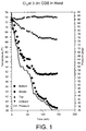
- FIG. 1 illustrates external cylinder wall temperature as a function of time at several locations on a 7 l Cl 2 cylinder for a gas flowrate of 3 l/m. Vapor pressure in the cylinder as a function of time is also illustrated.
- the external cylinder temperature becomes substantially cooler than the ambient temperature.
- the coldest temperature on the cylinder surface corresponds to the location of the liquid-vapor interface since the vaporization process occurs in that region.
- the pressure inside the cylinder is indicative of a liquid temperature that is colder than the lowest external wall temperature.
- FIG. 2 depicts vapor pressure of chlorine as a function of liquid temperature in the cylinder (solid line), and cylinder pressure as a function of measured external cylinder temperature for flowrates of 0.16, 1 and 3 l/m (individual points). Because the temperature of the liquid must be colder than the coldest external cylinder temperature, natural convection currents are induced. These natural convection currents help to homogenize the temperature in the liquid phase.
- the rate of change of cylinder temperature and pressure is a balance of the rate of heat transfer to the cylinder, the energy requirements specified by the flowrate and the thermal mass of the cylinder.
- the overall heat transfer coefficient U is less than the smallest of the individual resistances to heat transfer (i.e., each term in the denominator of equation (I)).
- the values for the heat transfer coefficients were based on Table 1-2 of Heat Transfer , by J.P. Holman, using natural convection as the primary mechanism for both internal and external heat transfer.
- the overall heat transfer coefficient U is equal to 4.47 W/m 2 K, which is very close to the value for the external heat transfer coefficient h o .
- the external heat transfer coefficient h o is not constant along the entire surface of the cylinder. Because air enters the cabinet near the bottom of the cabinet, the direction of flow is across the cylinder (i.e., transverse to the longitudinal axis of the cylinder) in that region of the cabinet. In the region near the top of the cabinet, the air is traveling primarily in a vertical direction (i.e., parallel to the longitudinal axis of the cylinder).
- FIGS. 3 and 4 illustrate air velocity vectors within a gas cabinet at two different planes 300, 400 transverse to the longitudinal axes 301, 401 of the cylinders.
- Plane 300 in FIG. 3 is located where air is drawn into the gas cabinet at a position about 0.15 m from the bottom of the cabinet, while plane 400 is about 1 m from the bottom of the gas cabinet in FIG. 4.
- the flow is primarily across the cylinders, transverse to the longitudinal axes 301 thereof near the bottom of the gas cabinet.
- FIG. 4 shows that the air flow is primarily parallel to the cylinder longitudinal axis 401 near the top of the gas cabinet.
- the value of the external heat transfer coefficient h o ranges from about -36 to about -2 W/m 2 K., and the average value of the external heat transfer coefficient h o is -10.5 W/m 2 K. Based on the results shown in FIG. 5, the external heat transfer coefficient was determined to be largest at a point opposite to the position at which ambient air is drawn into the cabinet. This results from the air direction and velocity magnitude in this region.
- the external cylinder temperature also increases (assuming an identical process gas flowrate).
- a higher process gas flowrate can be utilized, thereby maintaining a similar difference in temperature between the ambient and the cylinder. It is, however, undesirable to withdraw material from the cylinder with too large of a temperature difference between the ambient and cylinder (and by analogy, between the cylinder and the liquid stored in the cylinder). The reason for this is the possible entrainment of liquid droplets in the gas withdrawn from the cylinder, resulting from different boiling phenomena. As the temperature difference between the cylinder and the liquid increases, the evaporation process changes from one of interface evaporation to a bubbling type of phenomena.
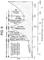
- FIG. 6 illustrates the qualitative variation of the internal heat transfer coefficient h i with the temperature difference ⁇ T x between the cylinder T w and the liquid stored in the cylinder T sat .
- the evaporation process occurs at the liquid-vapor interface.
- the vaporization process progresses through the formation of vapor bubbles in the liquid.
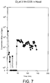
- the bubbles rise to the interface, it becomes possible for small ultrafine droplets to become entrained in the gas flow. This entrainment of droplets has been observed, and is quantified for a Cl 2 cylinder with a 3 slm flowrate in FIG.
- FIG. 8 illustrates the concentration of liquid droplets in a 1 slm Cl 2 gas flow as a function of time when using the exemplified block valve.
- a large number of droplets in the gas flow from the head space are initially present when opening the cylinder valve. These droplets exist in the head space in supersaturated conditions. As the flow of gas is continued, the droplets are eventually purged from the head space. The number of droplets in the gas flow is thereby reduced. It is believed that the droplets detected during the early stages are formed by a partial expansion process which occurs when the cylinder valve is opened, and/or that the droplets can be attributed to a number of equilibrium droplets suspended in the head space of the cylinder.
- the length of time that these droplets are in the exiting gas is related to the liquid level in the cylinder (or in other words, to the head space volume) and the flowrate of the gas being removed from the cylinder. It has been determined that, if this gas containing entrained droplets is heated at constant pressure, the droplets can be evaporated.
- the presence of liquid in the gas delivery system may be a result of the process of withdrawing the gas from the cylinder, local cooling due to ambient fluctuations, or droplet formation during the expansion process.
- the material passes into the two phase region.
- the other gases listed in Tables 1 and 2 do not pass into the two phase region for an isenthalpic pressure reduction.
- thermodynamic path that is followed during expansion is not isenthalpic (the actual expansion process is nearly isentropic because of the conversion of internal energy to kinetic energy) and has the possibility of entering the two phase region if inequality (II), below, is satisfied: wherein the left hand side of the inequality represents the change in pressure with the change in temperature at constant entropy, and the right hand side of the inequality represents the derivative of the vapor pressure as a function of temperature.
- FIG. 10 a preferred embodiment of the inventive system and method for delivery of a gas from a liquified state will be described. It is noted, however, that the specific configuration of the system will generally depend on factors such as cost, safety requirements and flow requirements of the cabinet.
- the system comprises one or more compressed liquified gas cylinders 002 housed within a gas cabinet 003.
- the specific material contained within the liquified gas cylinder is not limited, but is process dependent. Typical materials include these specified in Tables 1 and 2, e.g., NH 3 , AsH 3 , BCl 3 , CO 2 , Cl 2 , SiH 2 Cl 2 , Si 2 H 6 , HBr, HCl, HF, N 2 O, C 3 F 8 , SF 6 , PH 3 and WF 6 .
- Gas cabinet 003 includes a grate 004 through which purging air enters the cabinet. This purging air is preferably dry, and is exhausted from the gas cabinet through exhaust duct 005.
- the heat transfer rate between the ambient and gas cylinder is increased such that the liquid temperature in the gas cylinder is not increased to a value above the ambient temperature.
- suitable means for increasing the heat transfer rate include one or more plenum plates or an array of slits 006 in gas cabinet 003 through which air can be forced across the cylinder.
- An air blower or fan 007 can be used to force the air through the plenum plates or slits. Blower or fan 007 can preferably operate at variable speeds.
- Suitable plenum plates having a maximum heat transfer coefficient for a given pressure drop are commercially available from Holger Martin. Such components can easily be incorporated into a gas cabinet with minimal or no increase in gas cabinet size.
- the plenum plates or slits can optionally be modified by adding fins which can direct air flow. It is preferable that the fins direct the air flow primarily towards the cylinder in the vicinity of the liquid-vapor interface.
- the above-described scale cover/heater is particularly beneficial, since it can be fit into existing gas cabinets with negligible displacement of the gas cylinders, Therefore, it is unnecessary to retrofit or modify existing gas cabinets or gas piping.
- the temperature of the plenum plates or slits can also be electrically controlled to a value slightly higher than ambient to further increase the rate of heat transfer.
- the temperature of the plenum plates or slits should be limited such that evaporation occurs only at the liquid-vapor interface, and to avoid heating the liquid inside the cylinder to a temperature above ambient.
- radiant panel heaters or a heater disposed below the cylinder can be used to increase the heat transfer rate between the ambient and gas cylinder.
- the heat transfer rate is increased by use of a hot plate-type heater.
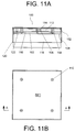
- FIGS. 11A and B illustrate side-sectional and top views, respectively, of an exemplary hot-plate type heater.
- Heater 100 is in the form of a cover for a gravimetric scale, which scale can be enclosed by the heater.
- Such scales are known in the art and are conventionally disposed on the floor of gas cabinets. Cylinders containing liquified gases typically sit directly on the scale, with the scale providing a measure of the amount of material remaining in the cylinder.
- the heated scale cover exemplified in FIGS. 11A and B
- the cylinder is disposed directly on the covered scale.
- Heater 100 includes a top surface, i.e., top plate, 102 attached to a bottom surface, i.e., bottom plate 104, by means of a center spacer 106, a plurality of side spacers 108 and screws 110.
- the heater further includes a cavity 112 which contains a heating element (not shown).
- Suitable heating elements include, but are not limited to, resistance-type heaters such as electrical heating tape or preferably, self regulating-type heaters, such as heat trace.
- the heating element is preferably capable of being coiled within cavity 112.
- the heating element should be capable of operation at temperatures of from ambient to about 220°F.
- the end can be fixed to a cutout 114 in center spacer 106.
- the heating element can be coiled around the center spacer and optionally around the side spacers until the desired area is covered. It is desirable that the heating element cover the area of contact between the gas cylinder and the scale.
- a significant length of, for example, up to 16 feet or more of the heating element can be coiled within the heater. Given a 16 foot length of 20 watt/foot heating element, 320 watts of heat would be available from the heater.
- the bottom of cavity 112 is preferably insulated using an insulation layer 116 to ensure that the heat from the heating element is directed upwards, towards the bottom of the gas cylinder.
- the insulation layer also serves to maintain contact between the heating element and top plate 102.
- the heater further includes front and rear panels 118, side panels 120 and bridge 122, which allow the heater to fit over the cylinder scale.
- Top plate 102 is preferably made of a stainless steel, while the front, rear and side panels and the bridge are preferably constructed of aluminum or carbon steel.
- the temperature can be controlled in various ways.
- the power to the heater can be turned on or off based on the energy requirements of the gas cylinder. A preferred control method and algorithm for this purpose are described below.
- heater 100 can include a concave, or cup-shaped, piece which can be attached to top plate 102 of the heater.
- the concave piece preferably conforms to the shape of the bottom of the gas cylinder such that more effective heat transfer to the cylinder is possible.
- the concave piece should be formed of a relatively hard material which is resistant to deformation upon contact with the gas cylinder and which is effective to transfer heat to the cylinder. Such materials include, for example, carbon steel and a stainless steel.
- FIGS. 12 is a graph illustrating the effect of heater temperature on the presence of liquid droplets in a gas flow as a function of time.
- the test was run with C 3 F 8 at a flowrate of 5 slm, with the heater temperature being varied between about 78°F and 112°F.
- the heater employed was a hot plate-type heater as described above. Significant reductions in liquid droplet concentration were obtained with an increase in the temperature of the heater.
- a radiant heater or a hot plate-type heater can be used in combination with a blower or fan as well as with the plenum plates or slits described above.
- the gas is withdrawn from cylinder 302 through a gas line connected thereto.
- Preferred materials of construction for the gas line include electropolished stainless steel, hastelloy or monel, due to the corrosive nature of the gases.
- the gas line further includes means 304 for reducing the pressure of the gas withdrawn from the cylinder.
- means 304 for reducing the pressure of the gas withdrawn from the cylinder As described above, a pressure regulator or valve is suitable for this pressure reduction step. Such components are commercially available, for example, from AP Tech.
- the system can further include means 306 for superheating the gas withdrawn from the gas cylinder, the superheating means being disposed upstream of the pressure reducing means.
- Superheating the gas can prevent the deleterious effects stemming from the transfer of liquid droplets or mist in the cylinder head space, which are characteristic during initial gas flow from the cylinder.
- the superheating means ensures that the fluid is entirely in the vapor form by vaporizing any entrained liquid droplets. Furthermore, the superheating means ensures a minimum degree of superheating of this vapor to avoid the possibility of droplet formation in a subsequent expansion process.
- the superheating means can be any unit which effectively removes the entrained liquid droplets from the gas stream, such as a heated line.
- the line can be heated by, for example, a resistance-type heater provided along a length of the gas line, such as electrical heating tape, or a self regulating-type heater such as heat trace can be used.
- the superheating means can take the form of a modified block valve.
- the block valve 400 is connected to the gas cylinder through suitable gas piping and fittings (not shown in figure).
- the piping is connected to the block valve at inlet port 402.
- the block valve further includes purge gas inlet port 404, through which an inert gas, such as nitrogen or argon, can be introduced into the valve.
- the process gas introduced through inlet port 402 exits the valve through outlet port 406, which is connected to the point of use, for example, a processing tool, through suitable gas piping, fittings, valves, etc.
- the block valve is operated by actuators 408 and 410, which can open or close the gas flow paths within the valve.
- the pressure of the gas within the valve is monitored by a pressure measurement device, such as pressure transducer 412.
- Heat can be supplied to block valve 400 by one or more heating elements 414 attached to or inserted into the block valve.
- the heating elements should have the capability of providing a constant heat flux to the block valve.
- Suitable heating elements include, but are not limited to, a self regulating-type heater such as heat trace, a resistance-type heaters such as electrical heating tape or a cartridge heater.
- one or more strips of heat trace 414 can be attached to the backside of the block valve for this purpose.
- the heater can be kept on at all times.
- a cartridge heater it can be inserted into the block valve, for example at position 416.
- the block valve preferably includes a sintered metal disc 418 added to outlet port 406.
- Metal disc 418 can take the form of a filter having a pore size of, for example, from about 1 to 60 ⁇ m, preferably from about 5 to 30 ⁇ m. Since metal disc 418 is heated by the heating element, it provides additional heated surface area for the gas to contact. Metal disc 418 thereby helps to provide the requisite energy to ensure that any liquid in the gas stream is vaporized.
- the metal disk can be welded in place in the outlet port.
- the material of construction of the metal disk is selected on the basis of the process gas flowing through the valve. That is, the material of construction should be compatible with the process gas to prevent contamination of the process gas as well as to prevent damage to the various gas line components.
- Typical materials for the metal disc include but are not limited to stainless steel (e.g., 316L), hastelloy and nickel.
- the superheating means can be a unit for heating air or inert gas, preferably dry, which is blown onto a section of the gas line by a blower or fan.
- the heated air or inert gas can also be used to heat the gas stream by use of a coaxial line structure.
- the superheating means can include a heated gas filter and/or a heated gas purifier provided in the line.
- the sintered metal disc described above is one such type of filter.
- the heated gas filter can remove particulates in the gas and provides a large surface area for heat transfer.
- the heated gas purifier can remove unwanted contaminants from the gas in the cylinder and provides a large surface area for heat transfer.
- FIGS. 15A and 15B demonstrate the effectiveness of a superheater in reducing the number of liquid droplets observed when initially opening a gas cylinder valve.
- Tests at 5 slm C 3 F 8 with no superheater (FIG. 15A) and with a superheater (FIG. 15B) were run.
- the superheater employed was a heated block valve as described above.
- the number of liquid droplets observed in the gas flow with no superheater ranged from about 3800 per l to about 19,000 per l. Those droplets were effectively eliminated when using the superheater.
- the system can further include means for integratably controlling the heat transfer rate increasing means 308 and the superheating means 306.
- This control means allows for precise control of cylinder pressure and temperature, as well as the degree of superheating the gas withdrawn from the cylinder upstream of the pressure reducing means 304.
- a constant cylinder pressure, a cylinder temperature at or slightly below ambient temperature, and a desired degree of gas superheating prior to expansion can all be attained.
- Suitable control means are known in the art, and include, for example, one or more programmable logic controllers (PLCs) or microprocessors.
- Pressure sensor 310 monitors the pressure at the exit of cylinder 312. The pressure read by the pressure sensor indicates the pressure at which vaporization is occurring, and further provides input to a controller 314 which adjusts the heat transfer rate increasing means. This adjustment can be based, for example, on the instantaneous pressure value and its history.
- An optional cylinder overheating sensor 316 can also be provided to override the controller in the event a predetermined temperature limit is exceeded.
- the superheating means 306 and the gas temperature immediately upstream of the pressure reduction device 304 are controlled in a similar manner to that described above.
- the control system for the superheating means includes temperature sensor 318, which is located downstream from superheating means 306 and upstream from the pressure reduction means 310. Based on the output of the temperature sensor, controller 314 sends a control signal to superheater 306, thereby adjusting the gas temperature.
- the setpoint for the superheating control temperature will depend, for example, on the current cylinder pressure and cylinder wall temperature. As the implied difference between the cylinder wall temperature and the liquid temperature (as defined by the vapor pressure curve) increases, the amount of energy required by the superheater increases since a greater number of liquid droplets are being withdrawn.
- a similar equation is applicable in the case in which the degree of super-heating is controlled as a function of temperature. For certain gases, it may be possible that the superheater setpoint will not change with cylinder pressure. This is most likely true for low pressure gases.
- the exemplary control system is used in conjunction with a gas delivery system which includes a scale 602 and a bottom heater/scale cover 604 as well as a block valve superheater 606 as described above.
- the block valve is heated with a self-regulating heating element, such as heat trace.
- a self-regulating heating element such as heat trace.
- the control system determines the energy requirements of the gas cylinder, and switches the power to the bottom heater on or off depending on those requirements.
- the exemplary control system is based on one or more programmable logic controllers (PLCs) 608, although other known forms of computer control are also envisioned.
- the algorithm requires as input variables, among others, gas cylinder pressure P and gas cylinder mass (i.e., tare weight) M t .
- the cylinder pressure is measured by a pressure measuring device, such as a pressure transducer in the heated block valve.
- the cylinder mass is measured by the scale covered by the lower heater upon which the cylinder is set in the gas cylinder cabinet.
- the cylinder pressure and mass are read by the PLC, and the energy requirements of the cylinder are thereby directly correlated with the cylinder's usage.
- the weight of the product remaining in the cylinder M p is calculated by subtracting the tare weight (i.e., the empty cylinder weight, which is an input variable) from the cylinder weight M, as measured by the scale. All weights are measured in pounds.
- M p is next compared with the inequality, ( ⁇ g /1000.0*V*s)*2.2, in which ⁇ g is the density of the gas vapor at room temperature and cylinder pressure, measured in kg/m 3 .
- ⁇ g is provided by a table which is input into the PLC.
- V an input variable
- s is a safety factor.
- the safety factor is used to prevent complete depletion of the liquid in the gas cylinder since impurities tend to be concentrated in the residual liquid at the bottom of the cylinder. Such impurities are potentially harmful to the components of the gas delivery system as well as to the semiconductor devices being formed. While not being limited in any way, typical values for the safety factor s are from 1.1 to 1.3
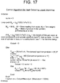
- T ldK (B/(ln(P)-A), wherein A and B are constants determined from the vapor pressure curve of the particular material.
- A is the y-intercept of the vapor pressure curve, while B is the slope of the vapor pressure curve.
- a table of values for A and B is preprogrammed into the PLC. The pressure P in psia is measured by the pressure sensor.
- K c T gain *M, wherein T gain represents the heat capacity of the gas cylinder and liquid contained therein per second, in units of W/°F-lb. While not limited in any way, T gain can have a value, for example, of from 10 to 100 W/°F-lb. In the exemplary system, T gain is equal to about 30 W/°F-lb. K c represents the power required to raise the temperature of the system (cylinder and liquid) 1°F, and has units of W/°F.
- Output K c *Error+K c /tau* sume.
- Tau is a constant which is based on the delay time in the response of the heater to the control system.
- the "Fraction On” function represents the period of time for which the heater is to be turned on.
- Maximum output represents the maximum power of the heater, in watts.
- the algorithm and control system described above can maximize gas flow rates as well as the length of time a cylinder can deliver such high flows.
- a particularly beneficial aspect of the control system described above makes it possible to scale the system up to assure all vapor phase delivery of gases from significantly larger liquified gas sources than cylinders, such as bulk storage vessels and trailers.
- the temperature of the liquid inside the cylinder vis-a-vis the cylinder temperature is maintained at a value equal to or slightly less than ambient temperature, strict thermal management downstream of the heater is rendered unnecessary. Also, due to the lack of any thermal driving force associated with the inventive system and method, condensation in the piping system downstream of the cylinder cabinet can be avoided.
Landscapes
- Engineering & Computer Science (AREA)
- Mechanical Engineering (AREA)
- General Engineering & Computer Science (AREA)
- Filling Or Discharging Of Gas Storage Vessels (AREA)
- Feeding, Discharge, Calcimining, Fusing, And Gas-Generation Devices (AREA)
- Separation By Low-Temperature Treatments (AREA)
- Chemical Vapour Deposition (AREA)
- Control Of Temperature (AREA)
Applications Claiming Priority (4)
| Application Number | Priority Date | Filing Date | Title |
|---|---|---|---|
| US893499 | 1992-06-04 | ||
| US08/753,413 US5761911A (en) | 1996-11-25 | 1996-11-25 | System and method for controlled delivery of liquified gases |
| US08/893,499 US6076359A (en) | 1996-11-25 | 1997-07-11 | System and method for controlled delivery of liquified gases |
| US753413 | 1997-07-11 |
Publications (3)
| Publication Number | Publication Date |
|---|---|
| EP0844431A2 true EP0844431A2 (de) | 1998-05-27 |
| EP0844431A3 EP0844431A3 (de) | 1999-04-28 |
| EP0844431B1 EP0844431B1 (de) | 2008-07-09 |
Family
ID=27115739
Family Applications (1)
| Application Number | Title | Priority Date | Filing Date |
|---|---|---|---|
| EP97402751A Expired - Lifetime EP0844431B1 (de) | 1996-11-25 | 1997-11-17 | Vorrichtung und Verfahren zur gesteuerten Abgabe von Flüssiggas |
Country Status (7)
| Country | Link |
|---|---|
| US (1) | US6076359A (de) |
| EP (1) | EP0844431B1 (de) |
| JP (1) | JP4531873B2 (de) |
| KR (1) | KR19980042687A (de) |
| CN (1) | CN1109128C (de) |
| SG (3) | SG77230A1 (de) |
| TW (1) | TW372263B (de) |
Cited By (7)
| Publication number | Priority date | Publication date | Assignee | Title |
|---|---|---|---|---|
| WO2002003000A1 (en) * | 2000-07-01 | 2002-01-10 | S J International Limited | Glass chiller |
| FR2834045A1 (fr) * | 2001-12-20 | 2003-06-27 | Air Liquide Electronics Sys | Procede et systeme de production d'une solution de produit chimique a partir de la phase gazeuse d'un produit chimique |
| WO2003068680A1 (en) * | 2002-02-11 | 2003-08-21 | L'air Liquide- Societe Anonyme A Directoire Et Conseil De Surveillance Pour L'etude Et L'exploitation Des Procedes Georges Claude | Ammonia vapor generation |
| FR2863341A1 (fr) * | 2003-12-04 | 2005-06-10 | Air Liquide Electronics Sys | Systeme de chauffage de bouteilles de gaz liquefie par induction |
| WO2008002565A3 (en) * | 2006-06-28 | 2008-02-07 | Praxiar Technology Inc | Energy delivery system for a gas transport vessel |
| EP1354165A4 (de) * | 2001-01-05 | 2009-04-22 | Praxair Technology Inc | Gasablieferung mit hohen strömungsgeschwindigkeiten |
| US11549702B2 (en) | 2019-04-25 | 2023-01-10 | Beneq Oy | Precursor supply cabinet |
Families Citing this family (30)
| Publication number | Priority date | Publication date | Assignee | Title |
|---|---|---|---|---|
| KR100378409B1 (ko) * | 1998-09-03 | 2003-03-29 | 닛폰산소 가부시키가이샤 | 반도체 프로세스가스의 대량 공급장치 |
| US6199384B1 (en) * | 1999-07-09 | 2001-03-13 | American Air Liquide Inc. | System and method for controlled delivery of liquefied gases including control aspects |
| US6363728B1 (en) * | 2000-06-20 | 2002-04-02 | American Air Liquide Inc. | System and method for controlled delivery of liquefied gases from a bulk source |
| US20030209016A1 (en) * | 2000-11-06 | 2003-11-13 | Exta Exclusive Thermodynamic Applications Ltd. | Method and system for supplying vaporized gas on consumer demand |
| US6957013B2 (en) * | 2001-06-08 | 2005-10-18 | Algas-Sdi International Llc | Fluid heater |
| US6816669B2 (en) * | 2001-06-08 | 2004-11-09 | Algas-Sdi International Llc | Vaporizer with capacity control valve |
| AU2002361769A1 (en) * | 2001-12-17 | 2003-06-30 | Integrated Flow Systems, Llc | Electronic controller for chemical delivery systems |
| US7021329B2 (en) * | 2003-06-11 | 2006-04-04 | Itt Manufacturing Enterprises, Inc. | Vaporizing pressure regulator |
| CN1297778C (zh) * | 2004-12-27 | 2007-01-31 | 西安交通大学 | 一种分离器及利用其消除严重段塞流的分相输送方法 |
| US20070163273A1 (en) * | 2006-01-17 | 2007-07-19 | American Air Liquide, Inc. | Liquid Purge for a Vaporizer |
| US20070204631A1 (en) * | 2006-03-03 | 2007-09-06 | American Air Liquide, Inc. | Liquefied Chemical Gas Delivery System |
| CN101315869B (zh) * | 2007-05-28 | 2010-06-09 | 中芯国际集成电路制造(上海)有限公司 | 气体控制器、气体控制器的保护装置及保护方法 |
| US8356487B2 (en) * | 2007-09-07 | 2013-01-22 | SPX Cooling Technologies | Control system and method for vaporizer with heating tower |
| US8833078B2 (en) | 2009-02-27 | 2014-09-16 | D2Bg Llc | Compressed gas-driven device with passive thermodynamic composition |
| US8635873B2 (en) * | 2009-02-27 | 2014-01-28 | D2Bg Llc | Compressed gas-driven device with passive thermodynamic composition |
| KR101402381B1 (ko) | 2013-04-11 | 2014-06-03 | 한국가스공사 | Lng 탱크 컨테이너를 이용한 원격지 천연가스 공급 스테이션 및 이를 이용한 천연가스 공급 방법 |
| KR102409471B1 (ko) * | 2014-12-22 | 2022-06-16 | 가부시키가이샤 호리바 에스텍 | 유체 가열기 |
| EP3174071B1 (de) * | 2015-11-30 | 2018-11-14 | General Electric Technology GmbH | Verfahren und anlage zum befüllen einer gasisolierten elektrischen geräteanordnung, die eine mischung aus (cf3)2cfcn und co2 umfasst |
| TWI616612B (zh) * | 2016-06-29 | 2018-03-01 | 法液空電子設備股份有限公司 | 液化氣體供給系統的加熱控制系統和方法 |
| FR3054018B1 (fr) | 2016-07-13 | 2018-08-10 | L'air Liquide, Societe Anonyme Pour L'etude Et L'exploitation Des Procedes Georges Claude | Distribution d'un melange gazeux dielectrique vers un appareillage haute tension |
| US11427907B2 (en) * | 2016-07-20 | 2022-08-30 | Showa Denko K.K. | Gas supply apparatus and gas supply method |
| CN107255220A (zh) * | 2017-05-10 | 2017-10-17 | 浙江电力建设监理有限公司 | 一种高寒地区特高压换流站sf6连充装置及加热控制方法 |
| CN108341078B (zh) * | 2018-01-26 | 2020-05-08 | 中国工程物理研究院核物理与化学研究所 | 一种微升级液体注入控制方法 |
| WO2019186249A1 (en) * | 2018-03-26 | 2019-10-03 | Genex Science And Technologies Pvt. Ltd. | A gas boosting device for a gas cylinder |
| JP6961161B2 (ja) * | 2019-05-14 | 2021-11-05 | 日本エア・リキード合同会社 | 固体材料容器用キャビネット |
| US11155758B2 (en) * | 2019-05-30 | 2021-10-26 | Airgas, Inc. | Method of dosing a system with HCL then evacuating and purging |
| CN115461843B (zh) * | 2020-04-28 | 2025-07-15 | 中央硝子株式会社 | 组合物的供给方法、组合物以及干蚀刻方法 |
| JP7582926B2 (ja) * | 2021-10-18 | 2024-11-13 | 本田技研工業株式会社 | 水素充填装置の制御方法、及び、水素充填装置 |
| CN117568782B (zh) * | 2023-10-30 | 2025-03-25 | 研微(江苏)半导体科技有限公司 | 化学反应源供应系统及半导体加工装置 |
| CN119536410B (zh) * | 2024-12-05 | 2025-09-16 | 无锡海鼎微电子有限公司 | 一种l型真空管道温度控制方法、系统及智能终端 |
Family Cites Families (50)
| Publication number | Priority date | Publication date | Assignee | Title |
|---|---|---|---|---|
| US2842942A (en) * | 1955-08-25 | 1958-07-15 | Herrick L Johnston Inc | Apparatus for dispensing gas from a container of liquefied gas |
| US3282305A (en) * | 1964-02-20 | 1966-11-01 | Gen Dynamics Corp | Cylinder filling apparatus |
| US3650290A (en) * | 1968-11-19 | 1972-03-21 | Air Reduction | Pressure control system for cryogenic fluids |
| US3648018A (en) * | 1970-02-05 | 1972-03-07 | Dow Chemical Co | Transfer device for cryogenic fluids |
| US3939871A (en) * | 1975-01-28 | 1976-02-24 | Rockwell International Corporation | Burner block assembly |
| US4219725A (en) * | 1978-08-01 | 1980-08-26 | The Dow Chemical Company | Heating apparatus for vaporizing liquefied gases |
| DE2851862A1 (de) * | 1978-11-30 | 1980-06-04 | Linde Ag | Verfahren zur entnahme von gasen aus behaeltern |
| DE3042944A1 (de) * | 1980-11-14 | 1982-07-01 | Linde Ag, 6200 Wiesbaden | Verfahren und vorrichtung zum bereitstellen eines gases |
| FR2542421B1 (fr) * | 1983-03-08 | 1985-07-05 | Air Liquide | Procede et appareil pour produire un gaz a haute purete par vaporisation d'un liquide cryogenique |
| DE3506932A1 (de) * | 1985-02-27 | 1986-08-28 | Messer Griesheim Gmbh, 6000 Frankfurt | Vorrichtung zur erzeugung eines trockenen kalten gasstromes |
| DE3431524A1 (de) * | 1984-08-28 | 1986-03-06 | Battelle-Institut E.V., 6000 Frankfurt | Elektrische waegevorrichtung zur feuchtigkeitsbestimmung |
| CH669258A5 (de) * | 1985-05-10 | 1989-02-28 | Mettler Instrumente Ag | Temperaturfuehler fuer einen trocknungsaufsatz auf einer waage sowie die anordnung des temperaturfuehlers im trocknungsaufsatz der waage. |
| DE3530806A1 (de) * | 1985-07-27 | 1987-01-29 | Messer Griesheim Gmbh | Verfahren zum beheizen von druckgasflaschen |
| US4791277A (en) * | 1987-02-09 | 1988-12-13 | Montierth Garry L | Heating and insulation arrangement for a network of installed pipes and method |
| DE3709189A1 (de) * | 1987-03-20 | 1988-09-29 | Teves Gmbh Alfred | Hydraulische bremsanlage mit blockierschutz- und/oder antriebsschlupfregelung |
| US4989160A (en) * | 1988-05-17 | 1991-01-29 | Sci Systems, Inc. | Apparatus and method for controlling functions of automated gas cabinets |
| JPH02298774A (ja) * | 1989-05-10 | 1990-12-11 | Seiko Instr Inc | 自動冷却装置 |
| DE4001170A1 (de) * | 1990-01-17 | 1991-07-18 | Roland Man Druckmasch | Einschraubventilkoerper-bausatz, insbesondere fuer ein drosselventil |
| JP2781875B2 (ja) * | 1990-04-11 | 1998-07-30 | 日本エア・リキード株式会社 | ボンベ付ガス供給装置 |
| ES2110983T3 (es) * | 1990-04-20 | 1998-03-01 | Air Liquide | Procedimiento y dispositivo de elaboracion de nitrogeno ultrapuro. |
| JPH04110754U (ja) * | 1991-03-12 | 1992-09-25 | 横河電機株式会社 | 減圧cvd装置 |
| FR2675889A1 (fr) * | 1991-04-29 | 1992-10-30 | Bernier Jacques | Installation de transfert de fluide frigorigene pour installations frigorifiques comportant des moyens de chauffage ou de refroidissement de la bouteille par pompe a chaleur. |
| US5440477A (en) * | 1991-05-20 | 1995-08-08 | Creative Pathways, Inc. | Modular bottle-mounted gas management system |
| JPH04132300U (ja) * | 1991-05-27 | 1992-12-07 | 京セラ株式会社 | 液化ガス気化装置 |
| US5252134A (en) * | 1991-05-31 | 1993-10-12 | Stauffer Craig M | Integrated delivery system for chemical vapor from non-gaseous sources for semiconductor processing |
| JP2567099Y2 (ja) * | 1991-06-07 | 1998-03-30 | 山形日本電気株式会社 | ガス供給装置 |
| JP3099441B2 (ja) * | 1991-08-08 | 2000-10-16 | 日本電気株式会社 | 特殊材料ガスの供給方法 |
| JPH05283340A (ja) * | 1992-03-31 | 1993-10-29 | Sayama:Kk | 液体原料気化供給装置 |
| JP3149514B2 (ja) * | 1992-04-03 | 2001-03-26 | 富士通株式会社 | 気化ガスの供給方法及び供給装置 |
| JP2974192B2 (ja) * | 1992-04-10 | 1999-11-08 | 新東工業株式会社 | ウエハーと取付け板の接着設備 |
| US5582016A (en) * | 1992-05-07 | 1996-12-10 | Aerospace Design & Development, Inc. | Conditioning and loading apparatus and method for gas storage at cryogenic temperature and supercritical pressure |
| US5249434A (en) * | 1992-07-06 | 1993-10-05 | Wynn's Climate Systems, Inc. | System and method for automatic charging of refrigeration systems |
| JPH06123381A (ja) * | 1992-10-12 | 1994-05-06 | Hitachi Ltd | ガス供給系用部品 |
| JP3274895B2 (ja) * | 1992-12-02 | 2002-04-15 | ミリポア・コーポレイション | スロットルバルブ |
| JPH06294566A (ja) * | 1993-04-06 | 1994-10-21 | Teisan Kk | 半導体製造用のガスシリンダ冷却装置 |
| US5359787A (en) * | 1993-04-16 | 1994-11-01 | Air Products And Chemicals, Inc. | High purity bulk chemical delivery system |
| US5373701A (en) * | 1993-07-07 | 1994-12-20 | The Boc Group, Inc. | Cryogenic station |
| US5426944A (en) * | 1993-08-31 | 1995-06-27 | American Air Liquide, Inc. | Chemical purification for semiconductor processing by partial condensation |
| JP2695745B2 (ja) * | 1993-09-02 | 1998-01-14 | シーケーディ株式会社 | ガス供給装置 |
| JPH07269741A (ja) * | 1994-03-30 | 1995-10-20 | Takasago Thermal Eng Co Ltd | 結露防止型弁 |
| US5451258A (en) * | 1994-05-11 | 1995-09-19 | Materials Research Corporation | Apparatus and method for improved delivery of vaporized reactant gases to a reaction chamber |
| US5531245A (en) * | 1994-05-17 | 1996-07-02 | Reliance Electric Industrial Company | High temperature heated valve |
| US5377495A (en) * | 1994-06-27 | 1995-01-03 | Daigle; Regis G. | Temperature controlled thermal jacket for transfering refrigerant |
| US5485542A (en) * | 1994-07-18 | 1996-01-16 | Mks Instruments, Inc. | Heated fluid control valve with electric heating element and thermocouple wiring disposed in rotatable shaft |
| JPH08106972A (ja) * | 1994-10-03 | 1996-04-23 | Jamco Corp | パネルヒータ |
| JP2865585B2 (ja) * | 1995-02-21 | 1999-03-08 | シーケーディ株式会社 | ガス供給集積ユニット及びそのシステム |
| JP3534940B2 (ja) * | 1995-04-20 | 2004-06-07 | 株式会社荏原製作所 | 薄膜気相成長装置 |
| US5557940A (en) * | 1995-10-27 | 1996-09-24 | Hendricks; Roger G. | Portable heating unit for on-site charging of a cooling unit |
| US5965046A (en) * | 1996-04-17 | 1999-10-12 | Applied Materials, Inc. | Method and apparatus for baking out a gate valve in a semiconductor processing system |
| US5849076A (en) * | 1996-07-26 | 1998-12-15 | Memc Electronic Materials, Inc. | Cooling system and method for epitaxial barrel reactor |
-
1997
- 1997-07-11 US US08/893,499 patent/US6076359A/en not_active Expired - Fee Related
- 1997-11-12 SG SG1999001907A patent/SG77230A1/en unknown
- 1997-11-12 SG SG1999001909A patent/SG76611A1/en unknown
- 1997-11-12 SG SG1997004021A patent/SG55412A1/en unknown
- 1997-11-17 EP EP97402751A patent/EP0844431B1/de not_active Expired - Lifetime
- 1997-11-21 JP JP32169697A patent/JP4531873B2/ja not_active Expired - Lifetime
- 1997-11-24 KR KR1019970062298A patent/KR19980042687A/ko not_active Withdrawn
- 1997-11-24 CN CN97122788A patent/CN1109128C/zh not_active Expired - Lifetime
- 1997-11-24 TW TW086117543A patent/TW372263B/zh active
Cited By (13)
| Publication number | Priority date | Publication date | Assignee | Title |
|---|---|---|---|---|
| WO2002003000A1 (en) * | 2000-07-01 | 2002-01-10 | S J International Limited | Glass chiller |
| EP2375122A3 (de) * | 2001-01-05 | 2013-02-27 | Praxair Technology, Inc. | Gaszuführung mit hohen Durchflussraten |
| EP1354165A4 (de) * | 2001-01-05 | 2009-04-22 | Praxair Technology Inc | Gasablieferung mit hohen strömungsgeschwindigkeiten |
| FR2834045A1 (fr) * | 2001-12-20 | 2003-06-27 | Air Liquide Electronics Sys | Procede et systeme de production d'une solution de produit chimique a partir de la phase gazeuse d'un produit chimique |
| EP1323974A1 (de) * | 2001-12-20 | 2003-07-02 | Air Liquide Electronics Systems | Verfahren und Vorrichtung zur Herstellung einer Lösung chemischer Produkte aus ihrer Gasphase |
| WO2003068680A1 (en) * | 2002-02-11 | 2003-08-21 | L'air Liquide- Societe Anonyme A Directoire Et Conseil De Surveillance Pour L'etude Et L'exploitation Des Procedes Georges Claude | Ammonia vapor generation |
| US7347054B2 (en) | 2003-12-04 | 2008-03-25 | L'air Liquide, Societe Anonyme A Directoire Et Conseil De Surveillance Pour L'etude Et L'exploitation Des Procedes Georges Claude | System for heating tanks of liquefied gas by induction |
| EP1538390A3 (de) * | 2003-12-04 | 2010-05-26 | Air Liquide Electronics Systems | System zum Erhitzen von Flüssiggasflaschen per Induktion |
| FR2863341A1 (fr) * | 2003-12-04 | 2005-06-10 | Air Liquide Electronics Sys | Systeme de chauffage de bouteilles de gaz liquefie par induction |
| WO2008002565A3 (en) * | 2006-06-28 | 2008-02-07 | Praxiar Technology Inc | Energy delivery system for a gas transport vessel |
| US7778530B2 (en) | 2006-06-28 | 2010-08-17 | Praxair Technology, Inc. | Energy delivery system for a gas transport vessel containing low vapor pressure gas |
| US8447175B2 (en) | 2006-06-28 | 2013-05-21 | Praxair Technology, Inc. | Energy delivery system for a gas transport vessel containing low vapor pressure gas |
| US11549702B2 (en) | 2019-04-25 | 2023-01-10 | Beneq Oy | Precursor supply cabinet |
Also Published As
| Publication number | Publication date |
|---|---|
| KR19980042687A (ko) | 1998-08-17 |
| JP4531873B2 (ja) | 2010-08-25 |
| TW372263B (en) | 1999-10-21 |
| CN1213707A (zh) | 1999-04-14 |
| US6076359A (en) | 2000-06-20 |
| EP0844431B1 (de) | 2008-07-09 |
| EP0844431A3 (de) | 1999-04-28 |
| CN1109128C (zh) | 2003-05-21 |
| JPH10277380A (ja) | 1998-10-20 |
| SG76611A1 (en) | 2000-11-21 |
| SG55412A1 (en) | 1998-12-21 |
| SG77230A1 (en) | 2000-12-19 |
Similar Documents
| Publication | Publication Date | Title |
|---|---|---|
| US6076359A (en) | System and method for controlled delivery of liquified gases | |
| US5761911A (en) | System and method for controlled delivery of liquified gases | |
| US6363728B1 (en) | System and method for controlled delivery of liquefied gases from a bulk source | |
| US6199384B1 (en) | System and method for controlled delivery of liquefied gases including control aspects | |
| EP1354165B1 (de) | Gasablieferung mit hohen strömungsgeschwindigkeiten | |
| US5673562A (en) | Bulk delivery of ultra-high purity gases at high flow rates | |
| EP0939145B1 (de) | Verfahren und Vorrichtung zur kontinuierlichen Sättigung eines Gases | |
| KR101933225B1 (ko) | 환기 가스 관리 시스템 및 공정 | |
| US5894742A (en) | Methods and systems for delivering an ultra-pure gas to a point of use | |
| TWI521161B (zh) | 來自多重大量特殊氣體供應系統(bsgs系統)之同時氣體供應 | |
| US6474077B1 (en) | Vapor delivery from a low vapor pressure liquefied compressed gas | |
| EP4469717B1 (de) | Verbessertes flüssiggasprobenverdampferkonditionierungssystem und -verfahren | |
| HK1019237A (en) | System and method for controlled delivery of liquified gases | |
| EP1756468B1 (de) | System und verfahren zur zufuhr von nh3 mit hohem durchfluss zur herstellung von flachen anzeigepaneelen |
Legal Events
| Date | Code | Title | Description |
|---|---|---|---|
| PUAI | Public reference made under article 153(3) epc to a published international application that has entered the european phase |
Free format text: ORIGINAL CODE: 0009012 |
|
| AK | Designated contracting states |
Kind code of ref document: A2 Designated state(s): DE FR GB IT NL |
|
| RIN1 | Information on inventor provided before grant (corrected) |
Inventor name: WANG, HWA-CHI Inventor name: UDISCHAS, RICHARD Inventor name: JURCIK, BENJAMIN |
|
| PUAL | Search report despatched |
Free format text: ORIGINAL CODE: 0009013 |
|
| AK | Designated contracting states |
Kind code of ref document: A3 Designated state(s): AT BE CH DE DK ES FI FR GB GR IE IT LI LU MC NL PT SE |
|
| 17P | Request for examination filed |
Effective date: 19991028 |
|
| AKX | Designation fees paid |
Free format text: DE FR GB IT NL |
|
| RAP1 | Party data changed (applicant data changed or rights of an application transferred) |
Owner name: L'AIR LIQUIDE, S.A. A DIRECTOIRE ET CONSEIL DE SUR |
|
| 17Q | First examination report despatched |
Effective date: 20030114 |
|
| RAP1 | Party data changed (applicant data changed or rights of an application transferred) |
Owner name: L'AIR LIQUIDE, SOCIETE ANONYME POUR L'ETUDE ET L'E |
|
| RAP1 | Party data changed (applicant data changed or rights of an application transferred) |
Owner name: L'AIR LIQUIDE, SOCIETE ANONYME POUR L'ETUDE ET L'E |
|
| GRAP | Despatch of communication of intention to grant a patent |
Free format text: ORIGINAL CODE: EPIDOSNIGR1 |
|
| GRAS | Grant fee paid |
Free format text: ORIGINAL CODE: EPIDOSNIGR3 |
|
| GRAA | (expected) grant |
Free format text: ORIGINAL CODE: 0009210 |
|
| AK | Designated contracting states |
Kind code of ref document: B1 Designated state(s): DE FR GB IT NL |
|
| REG | Reference to a national code |
Ref country code: GB Ref legal event code: FG4D |
|
| REF | Corresponds to: |
Ref document number: 69738817 Country of ref document: DE Date of ref document: 20080821 Kind code of ref document: P |
|
| NLV1 | Nl: lapsed or annulled due to failure to fulfill the requirements of art. 29p and 29m of the patents act | ||
| PG25 | Lapsed in a contracting state [announced via postgrant information from national office to epo] |
Ref country code: NL Free format text: LAPSE BECAUSE OF FAILURE TO SUBMIT A TRANSLATION OF THE DESCRIPTION OR TO PAY THE FEE WITHIN THE PRESCRIBED TIME-LIMIT Effective date: 20080709 |
|
| PGFP | Annual fee paid to national office [announced via postgrant information from national office to epo] |
Ref country code: IT Payment date: 20081020 Year of fee payment: 12 |
|
| PLBE | No opposition filed within time limit |
Free format text: ORIGINAL CODE: 0009261 |
|
| STAA | Information on the status of an ep patent application or granted ep patent |
Free format text: STATUS: NO OPPOSITION FILED WITHIN TIME LIMIT |
|
| 26N | No opposition filed |
Effective date: 20090414 |
|
| PGFP | Annual fee paid to national office [announced via postgrant information from national office to epo] |
Ref country code: GB Payment date: 20081022 Year of fee payment: 12 |
|
| GBPC | Gb: european patent ceased through non-payment of renewal fee |
Effective date: 20091117 |
|
| PG25 | Lapsed in a contracting state [announced via postgrant information from national office to epo] |
Ref country code: GB Free format text: LAPSE BECAUSE OF NON-PAYMENT OF DUE FEES Effective date: 20091117 |
|
| PG25 | Lapsed in a contracting state [announced via postgrant information from national office to epo] |
Ref country code: IT Free format text: LAPSE BECAUSE OF NON-PAYMENT OF DUE FEES Effective date: 20091117 |
|
| REG | Reference to a national code |
Ref country code: FR Ref legal event code: PLFP Year of fee payment: 19 |
|
| REG | Reference to a national code |
Ref country code: FR Ref legal event code: PLFP Year of fee payment: 20 |
|
| PGFP | Annual fee paid to national office [announced via postgrant information from national office to epo] |
Ref country code: FR Payment date: 20161118 Year of fee payment: 20 Ref country code: DE Payment date: 20161121 Year of fee payment: 20 |
|
| REG | Reference to a national code |
Ref country code: DE Ref legal event code: R071 Ref document number: 69738817 Country of ref document: DE |