EP0844433B1 - Procédé et dispositif de combustion avec injection séparée du combustible et du comburant - Google Patents
Procédé et dispositif de combustion avec injection séparée du combustible et du comburant Download PDFInfo
- Publication number
- EP0844433B1 EP0844433B1 EP97402820A EP97402820A EP0844433B1 EP 0844433 B1 EP0844433 B1 EP 0844433B1 EP 97402820 A EP97402820 A EP 97402820A EP 97402820 A EP97402820 A EP 97402820A EP 0844433 B1 EP0844433 B1 EP 0844433B1
- Authority
- EP
- European Patent Office
- Prior art keywords
- oxidant
- fuel
- accordance
- streams
- angle
- Prior art date
- Legal status (The legal status is an assumption and is not a legal conclusion. Google has not performed a legal analysis and makes no representation as to the accuracy of the status listed.)
- Expired - Lifetime
Links
Images


Classifications
-
- F—MECHANICAL ENGINEERING; LIGHTING; HEATING; WEAPONS; BLASTING
- F23—COMBUSTION APPARATUS; COMBUSTION PROCESSES
- F23D—BURNERS
- F23D14/00—Burners for combustion of a gas, e.g. of a gas stored under pressure as a liquid
- F23D14/32—Burners for combustion of a gas, e.g. of a gas stored under pressure as a liquid using a mixture of gaseous fuel and pure oxygen or oxygen-enriched air
-
- F—MECHANICAL ENGINEERING; LIGHTING; HEATING; WEAPONS; BLASTING
- F23—COMBUSTION APPARATUS; COMBUSTION PROCESSES
- F23C—METHODS OR APPARATUS FOR COMBUSTION USING FLUID FUEL OR SOLID FUEL SUSPENDED IN A CARRIER GAS OR AIR
- F23C5/00—Disposition of burners with respect to the combustion chamber or to one another; Mounting of burners in combustion apparatus
- F23C5/08—Disposition of burners
- F23C5/14—Disposition of burners to obtain a single flame of concentrated or substantially planar form, e.g. pencil or sheet flame
-
- F—MECHANICAL ENGINEERING; LIGHTING; HEATING; WEAPONS; BLASTING
- F23—COMBUSTION APPARATUS; COMBUSTION PROCESSES
- F23C—METHODS OR APPARATUS FOR COMBUSTION USING FLUID FUEL OR SOLID FUEL SUSPENDED IN A CARRIER GAS OR AIR
- F23C6/00—Combustion apparatus characterised by the combination of two or more combustion chambers or combustion zones, e.g. for staged combustion
- F23C6/04—Combustion apparatus characterised by the combination of two or more combustion chambers or combustion zones, e.g. for staged combustion in series connection
- F23C6/045—Combustion apparatus characterised by the combination of two or more combustion chambers or combustion zones, e.g. for staged combustion in series connection with staged combustion in a single enclosure
-
- F—MECHANICAL ENGINEERING; LIGHTING; HEATING; WEAPONS; BLASTING
- F23—COMBUSTION APPARATUS; COMBUSTION PROCESSES
- F23C—METHODS OR APPARATUS FOR COMBUSTION USING FLUID FUEL OR SOLID FUEL SUSPENDED IN A CARRIER GAS OR AIR
- F23C7/00—Combustion apparatus characterised by arrangements for air supply
- F23C7/02—Disposition of air supply not passing through burner
-
- F—MECHANICAL ENGINEERING; LIGHTING; HEATING; WEAPONS; BLASTING
- F23—COMBUSTION APPARATUS; COMBUSTION PROCESSES
- F23D—BURNERS
- F23D14/00—Burners for combustion of a gas, e.g. of a gas stored under pressure as a liquid
- F23D14/20—Non-premix gas burners, i.e. in which gaseous fuel is mixed with combustion air on arrival at the combustion zone
- F23D14/22—Non-premix gas burners, i.e. in which gaseous fuel is mixed with combustion air on arrival at the combustion zone with separate air and gas feed ducts, e.g. with ducts running parallel or crossing each other
-
- F—MECHANICAL ENGINEERING; LIGHTING; HEATING; WEAPONS; BLASTING
- F23—COMBUSTION APPARATUS; COMBUSTION PROCESSES
- F23D—BURNERS
- F23D14/00—Burners for combustion of a gas, e.g. of a gas stored under pressure as a liquid
- F23D14/46—Details
- F23D14/48—Nozzles
- F23D14/58—Nozzles characterised by the shape or arrangement of the outlet or outlets from the nozzle, e.g. of annular configuration
-
- F—MECHANICAL ENGINEERING; LIGHTING; HEATING; WEAPONS; BLASTING
- F23—COMBUSTION APPARATUS; COMBUSTION PROCESSES
- F23L—SUPPLYING AIR OR NON-COMBUSTIBLE LIQUIDS OR GASES TO COMBUSTION APPARATUS IN GENERAL ; VALVES OR DAMPERS SPECIALLY ADAPTED FOR CONTROLLING AIR SUPPLY OR DRAUGHT IN COMBUSTION APPARATUS; INDUCING DRAUGHT IN COMBUSTION APPARATUS; TOPS FOR CHIMNEYS OR VENTILATING SHAFTS; TERMINALS FOR FLUES
- F23L7/00—Supplying non-combustible liquids or gases, other than air, to the fire, e.g. oxygen, steam
- F23L7/007—Supplying oxygen or oxygen-enriched air
-
- F—MECHANICAL ENGINEERING; LIGHTING; HEATING; WEAPONS; BLASTING
- F23—COMBUSTION APPARATUS; COMBUSTION PROCESSES
- F23D—BURNERS
- F23D2900/00—Special features of, or arrangements for burners using fluid fuels or solid fuels suspended in a carrier gas
- F23D2900/00012—Liquid or gas fuel burners with flames spread over a flat surface, either premix or non-premix type, e.g. "Flächenbrenner"
- F23D2900/00013—Liquid or gas fuel burners with flames spread over a flat surface, either premix or non-premix type, e.g. "Flächenbrenner" with means for spreading the flame in a fan or fishtail shape over a melting bath
-
- Y—GENERAL TAGGING OF NEW TECHNOLOGICAL DEVELOPMENTS; GENERAL TAGGING OF CROSS-SECTIONAL TECHNOLOGIES SPANNING OVER SEVERAL SECTIONS OF THE IPC; TECHNICAL SUBJECTS COVERED BY FORMER USPC CROSS-REFERENCE ART COLLECTIONS [XRACs] AND DIGESTS
- Y02—TECHNOLOGIES OR APPLICATIONS FOR MITIGATION OR ADAPTATION AGAINST CLIMATE CHANGE
- Y02E—REDUCTION OF GREENHOUSE GAS [GHG] EMISSIONS, RELATED TO ENERGY GENERATION, TRANSMISSION OR DISTRIBUTION
- Y02E20/00—Combustion technologies with mitigation potential
- Y02E20/34—Indirect CO2mitigation, i.e. by acting on non CO2directly related matters of the process, e.g. pre-heating or heat recovery
Definitions
- the present invention relates to a combustion process and an apparatus therefor that provides means of introducing a fuel and an oxidant in separate streams in the combustion chamber of a furnace, so that the fuel bums with the oxidant in a wide, luminous flame, and whereby the combustion of the fuel with the oxidant generates reduced quantities of nitrogen oxides (NO x ).
- Industrial high temperature processes such as glass or frit melting, ferrous and non ferrous materials smelting, use large amounts of energy to transform a variety of raw materials into a hot molten product, that is then cast, formed or otherwise disposed of in further stages of the industrial process.
- This operation is generally performed in large furnaces, that can produce as much as 500 tons per day of molten material.
- Combustion in the furnace of a fossil fuel such as natural gas, atomized fuel oil, propane, or the like, with an oxidant that contains oxygen is a preferred method of supplying the energy. In some cases, the combustion is supplemented by electric heating.
- the fuel and the oxidant are introduced in the furnace through burners, in order to generate flames.
- the transfer of energy from the flames to the material to be melted results from the combination of convection at the surface of the material, and radiation to the surface or into the material if it is transparent to the radiation.
- Flames that are highly radiant are usually preferred, because they provide better heat transfer and, thus, higher fuel.
- VSA Vacuum Swing Adsorption plant
- Conventional methods of combusting fuel and oxygen for heating furnaces utilize post mix oxy-fuel burners.
- Conventional oxy-fuel burners have a metallic body with inlets for a fuel and an oxidant with a high concentration of molecular oxygen, and means to transport the streams with separate coaxially oriented channels to multiple injectors located at the burner tip. These burners generate high temperature flames with the shape of a narrow pencil at the burner tip, which needs to be located far enough into the furnace, to avoid or reduce overheating of the furnace walls.
- a circulating fluid such as water provides the cooling.
- Such a burner is described, for example, in British Patent 1,215,925. Severe corrosion problems for the cooling jacket can arise particularly when the furnace atmosphere contains condensable vapors.
- the gas cooled oxy-fuel burner is an improvement of the water-cooled burner.
- the body of the burner is protected from the furnace radiation by a refractory brick often referred to as a burner block, that possesses a substantially cylindrical cavity that opens onto the furnace.
- the burner is usually mounted at the back of the cavity, and it usually contains concentric injectors of fuel and oxidant located in the cavity, recessed from the furnace inner wall.
- the brick and the burner are cooled by a peripheral annular flow of gas, usually the oxidant gas.
- Such burners are described e.g. in USP 5,346,390 and USP 5,267,850. With this type of burner, combustion starts in the burner block before reaching the furnace.
- the flame is confined in and directed by the cylindrical cavity as a narrow axisymmetric jet, and provides insufficient covering of the melt in the furnace.
- These flames have high peak temperatures and generate relatively large amounts of NO x , because there is a direct contact between the oxygen and the fuel without dilution by the combustion products.
- the use of high velocity oxidant jets requires the use of a high pressure oxidant supply, which means that the oxidant gas needs to be either produced or delivered at high pressure (the fuel gas is usually at relatively high pressure) or that the oxidant gas, such as the low pressure oxygen gas usually supplied by a VSA unit, has to be recompressed before being injected into the furnace.
- Melting furnaces such as glass furnaces represent a high capital investment. Thus it is desirable to extend the lifetime of a furnace as much as possible while maintaining productivity.
- One of the aging factors of a furnace is superstructure temperature: for example, it has been demonstrated that the rate of wear and corrosion of a glass furnace crown was accelerated when the furnace was operated at high temperature. This can oblige the glass maker to repair the furnace prematurely, or to reduce the furnace pull rate at the end of the furnace campaign in order to prevent a catastrophic failure.
- oxy-fuel burners that produce generally high temperature flames, it is very important that the flames are not deflected towards the crown which would result in local hot spots.
- elongated orifice such as a generally oval orifice depicted in the drawings
- Two adjacent fuel streams make an angle ranging from 0° to about 15°, preferably ranging from 0° to about 10°.
- the stream of oxidant flowing out of the at least one elongated orifice referred to as main oxidant, converges toward the fuel streams with an angle ranging from 0° to about 45°, preferably from about 2.5° to about 10°.
- the elongated orifice aspect ratio (maximum width [major axis] divided by maximum height [or minor axis]) preferably ranges from about 2 to about 8, more preferably from about 4 to about 6.
- the fuel streams are substantially parallel to the surface to be heated, or oriented relative to the surface to be heated with an angle not exceeding +10° or-10°, and the main oxidant stream converges towards the fuel streams and the surface to be heated.
- Another object of the present invention is to provide flames to heat up a melt contained in a furnace and to protect the crown of said melting furnace from overheating. Indeed, according to this aspect of the invention, the effect of the stream of oxidant exiting the generally rectangular orifice is to maintain the flame close to the melt and prevent the flame from lofting.
- Another object of the invention is a method and apparatus for supplying secondary oxidant around the at least two fuel streams in order increase flame luminosity by initiating combustion of the fuel before the main oxidant stream intersects the fuel streams in the combustion chamber, and by creating a fuel rich mixture where significant amounts of soot are formed. Subsequent combustion of the fuel rich mixture with soot with the main oxidant stream yields a luminous flame that provides efficient heat transfer.
- the flow of secondary oxidant is such that the secondary oxidant supplies between 0 and 50% of the total amount of oxidant required to obtain complete combustion of the fuel. Preferably, the amount of the secondary oxidant supplies between 0 and 25% of the total amount of oxidant required to obtain complete combustion of the fuel.
- the main oxidant and the secondary oxidant can be of different nature: for example, the main oxidant can be industrially pure oxygen (oxygen concentration greater than 88%), and the secondary oxidant can be ambient air.
- a means is provided to vary the flame luminosity and flame shape by changing the flows of main oxidant and secondary oxidant in such fashion that the total amount of oxygen in the main oxidant flow and in the secondary oxidant flow is sufficient to insure complete combustion of the fuel.
- the main oxidant and the secondary oxidant are provided by the same source, and the flame luminosity and shape are altered by changing the distribution of oxidant among the main oxidant stream flowing through the generally rectangular orifice and the secondary oxidant flowing around the at least two fuel streams.
- the flame luminosity increases as the amount of soot formed in the fuel rich mixture increases, and the flame geometry is modified when the mixing conditions of the fuel and the oxidant are modified.
- a burner assembly comprising:
- Another aspect of the present invention is the burner assembly described in the above where the main oxidant and the secondary oxidant have the same chemical composition, that further comprises splitting means to distribute the oxidant flow in the at least two oxidant outlets.
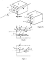
- FIGs. 1 a and 1 b represent schematic perspective views of burner blocks of the invention
- FIG. 2 represents a side sectional view of the burner block of FIG. 1a or 1 b, through the section indicated "A-A" of FIG. 1b, illustrating the inner geometry of the main oxidant cavity (9) comprises four sections;
- FIG. 3 represents an alternate embodiment of the inner geometry of the main oxidant cavity (9), wherein the diverging angle of section (12) is equal to (C), the diverging angle of section (11);
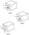
- FIGs. 4, 5, and 6 represent schematic perspective views of burner blocks of the invention
- FIGs. 7a and 7b represent side sectional views of other refractory blocks of the invention, illustrating preferred cavities (8) for the fuel injectors where the orifice (3) diameters are larger than the diameters of the remaining of the cavities;
- FIGs. 8a and 8b represent front elevation views of burner blocks of the invention, wherein natural gas injectors are placed in cavities;
- FIGs. 9, 10, 11 and 12 illustrate in side sectional elevations of three embodiments according to the present invention wherein there is provided a burner assembly in conjuction with a refractory block.
- fuel means, for example, methane, natural gas, liquefied natural gas, propane, atomized oil or the like (either in gaseous or liquid form) at either room temperature (about 25°C) or in preheated form.
- oxidant means a gas containing oxygen that can support combustion of the fuel. Such oxidants include air, oxygen-enriched air containing at least 50% vol. oxygen such as "industrially” pure oxygen (99.5%) produced by a cryogenic air separation plant, or non-pure oxygen produced for example by a vacuum swing adsorption process (about 88% vol.
- the main an secondary oxidants be the same in chemical composition, they could be different. That is, the secondary oxidant could be air while the primary oxidant is industrially pure oxygen, or vice versa; or the secondary oxidant could be impure oxygen while the primary oxidant is industrially pure oxygen, or vice versa.
- FIGs. 1 a and 1 b represent schematic perspective views of preferred burners (sometimes referred to herein as "burner blocks") (1) of the invention.
- fuel is injected in the combustion chamber of a furnace (2) through two outlets (3) located in a burner block hot face (4).
- the axis of the fuel streams out of burner block (1) are in the same plane, and make an angle (A) ranging from 0° (parallel arrangement) to about 30° with one another, (A) being preferably ranging from 0° to about 10°.
- Most of the oxidant required for the combustion of the fuel is injected trough an elongated orifice (5) located in hot face (4) of burner block (1).
- elongated orifice (5) is a slot.
- the flow of oxidant coming out of slot (5) makes an angle (B) with the direction of the fuel streams ranging from 0° to about 20°.
- Preferred (B) angles are in the range from about 2.5° to about 10°.
- the slot aspect ratio (maximum width divided by maximum height) ranges from about 2 to about 8, preferably from about 4 to about 6.
- the fuel is injected through three outlets (3) located in burner block hot face (4).
- the axis of the fuel streams out of burner block (1) are in the same plane, and make an angle (A) ranging from 0° to about 30° with one another.
- FIG. 2 represents a side sectional view of the burner block of FIG. 1 a or 1b, through the section indicated "A-A" of FIG. 1 b, illustrating the inner geometry of the main oxidant cavity (9) comprising four sections.
- the fuel streams originate from injectors (6) located in cylindrical cavities (7) of the burner block that open on the outlet orifices (3). Preferably the cavities are identical and located in a symmetrical arrangement relative to the slot (5).
- Secondary oxidant flows in the passageway (8) situated between the injectors (6) and the cavities (7). The amount of secondary oxidant supplies from 0% up to about 50% of the total amount of oxygen required to completely combust the fuel.
- injectors (6) are centered in cavities (7), and recessed from hot face (4) of block (1) by a distance ranging from 0 to about 2 times the diameter of orifice (3) of the cavities.
- the inner geometry of the main oxidant cavity (9) comprises preferably four sections.
- the first section (10) is generally cylindrical;
- the second section (10a) is generally cylindrical, of the same diameter as the first section;
- the second section (10a) makes the angle (B) with the axis of the first section;
- continuously attached to second section (10a) is a third section (11), generally conical with an angle (C) ranging from about 10° to about 120°, preferably ranging from about 10° to about 45°;
- a fourth section (12) connects continuously second section (10a) with main oxidant orifice (5).
- sections (10), (10a), (11), and (12) are shown in the sectional view of the block of FIG. 2 shown in FIG. 3: the diverging angle of section (12) is equal to (C), the diverging angle of section (11).
- the means to generate the at least two fuel streams are installed in the same cavity of a burner block.
- a burner block Such an arrangement is illustrated in FIG. 4, where two fuel injectors (6) are placed in a single cavity (7) of the burner block. Secondary oxidant flows in the passageway comprised between the fuel injectors (6) and the cavity (7).
- FIG. 5 Another such arrangement is illustrated in FIG. 5 where a liquid fuel injector (13) terminating with least two liquid fuel orifices (14) that generate separate fuel streams is placed in cavity (7).
- FIG. 6 represents an embodiment of the present invention similar to the embodiment of FIG. 1 but designed to use several fuels, where provision for an alternate fuel injector is made by placing an additional orifice (15) in the burner block: in one such embodiment, when fuel gas is used, the fuel is injected through orifices (3), and orifice (15) is not used; when a liquid fuel such as fuel oil is used, the fuel is injected through orifice (15), with orifices (3) left unused.
- the fuel velocity at the tip of the injectors (6) ranges from about 20 ms -1 to about 150 ms -1 , preferably from about 30 ms -1 about 80 ms -1 .
- the oxygen concentration of the oxidant is greater than 88%
- the oxidant velocity at the orifice (5) ranges from about 5 ms -1 to about 80 ms -1 , preferably from about 10 ms -1 to about 25 ms -1 .
- the ratio of natural gas velocity to main oxidant velocity is ranges from about 2 to about 4. It was found that a burner of the present invention designed for a given nominal firing rate could be used from 30% to 250% of its nominal rating.
- FIGs. 7a and 7b represent alternate preferred cavities (8) for the fuel injectors where the orifices (3) diameters are larger than the diameters of the remainder of the cavities (8). This provides improved protection of the injector tips (6a) from the hot furnace environment by recessing the injectors (6) farther from hot face (4) of the cavity without overheating block (1).
- the fuel cavities preferably have rounded or contoured edges at the exit point from the block.
- the main source of oxidant for the combustion of the fuel is the elongated orifice represented in FIGs. 1 a and 1 b, 4, 5, 6 by an oval slot 5.
- the main stream of oxidant (in other words, the oxidant emanating from slot (5)) is oriented toward the streams of fuel with an angle (B), and is also oriented to the surface to be heated. Reducing the angle (B) delays the mixing between the main oxidant and the fuel, which results in a longer combustion zone. However, very small (B) angles are not desirable, because the combustion zone becomes unstable. On the other hand, increasing the angle (B) increases the flame stability, but reduces the flame length, and pushes the flame towards the load.
- (B) should range from about 2.5° to about 10° when one wants to avoid that the flame approached the furnace load. Larger (B) angles can be found valuable in some applications where direct contact of the flame with the surface to be heated is looked for, for example in the production of ferrous and non-ferrous metals.
- the effect of the main oxidant stream is to maintain the flame below the plane of the burner, to prevent the flame from lofting toward the furnace crown (furnace crowns are present in, for example, glass tank furnaces), and effectively to reduce the crown temperature, because the energy is preferentially delivered to the load. Also, the combustion zone is preferentially pushed inside the furnace far from the sidewalls, which results in lower sidewall temperatures. With the combustion method of the invention, the mixing of oxidant and fuel is staged, thus resulting in a lower flame temperature and low nitrogen oxides emission rates.
- Additional benefits provided by secondary oxidant injection is an improved cooling of the gas injectors by the gas flows, and the creation of a protective layer of oxidant gas along the inside walls of the fuel cavities that prevents chemical reactions between the refractory burner block material and the fuel gas. Such reactions are due to the partial thermal decomposition of the fuel containing carbon and hydrogen into carbon atom C and hydrogen gas H 2 , and the subsequent reactions between C and H 2 with the refractory materials.
- the combustion method of the invention was tested at 500 kilowatt (1.7 MMBtu/hr) firing rate in a 4 meters long, 1 square meter cross section high temperature pilot furnace.
- the flame geometry, the flame stability and the flame luminosity were monitored with a video camera mounted on a periscope located in the roof of the furnace.
- a blue filter was inserted in front of the camera in order to eliminate part of the radiation emitted by the high temperature furnace walls.
- a prototype burner was built, with a main oxidant orifice (5) in the shape of a generally rectangular slot with rounded edges of dimensions 101.6 mm (4 inch) in width by 17.8 mm (0.7 inch) in height.
- the oxidant used for both the main oxidant flow and the secondary oxidant flow was 99.95% purity oxygen.
- the main oxidant velocity at the outlet of the slot was close to 15 ms -1 .
- Natural gas injectors (6) were placed in cavities (3), as indicated in FIG. 8a. By using two different sets of injectors, it was possible to change the natural gas velocity at the outlet of the injectors from 29 ms -1 to 55 ms -1 . For the smallest injectors the diameter of the cavities (3) that were used for the tests were 20.9 mm (0.824 inch) and 26.6 mm (1.049 inch). Only the larger fuel cavities (26.6 mm (1.049 inch)) could be used for the largest natural gas injectors.
- the distance (d) between the gas injectors was fixed at 114.3 mm (4.5 inch).
- the distance (H) between the main oxidant slot and the fuel injectors could be varied from 44.4 mm (1.75 inch) to 114.3 mm (4.5 inch).
- the angle (A) could be varied from 0 to 5 degrees, and the angle (B) could be varied from 0 to 10 degrees.
- the amount of secondary oxidant ranged from about 3% to about 13% of the total oxidant. This resulted in a more intense mixing between fuel and the increasingly higher velocity secondary oxidant flow, that tended to prevent soot formation, and to shorten the combustion zone.
- the nitrogen oxide (NOx) emission rate did not increase by more than 10% when the amount of secondary oxidant was increased in the indicated range: at 3% secondary oxidant, the NOx concentration was 945 ppm, and the maximum NOx concentration observed was 1035 ppm with increased secondary oxidant flow.
- a tube in tube oxy-fuel burner produced about 1800 ppm NOx.
- the combustion method of the invention depicted in Figure 8b was also tested at the 500 kilowatt (1.7 MMBtu/hr) scale in the high temperature pilot furnace, with a prototype burner having a main oxidant orifice of a generally oval shape with rounded edges, and of dimensions 101.6 mm (4 inches) in width by 17.8 mm (0.7 inch) in height.
- Natural gas was injected with three injectors centered in 20.9 mm (0.824 inch) in diameter cavities. The corresponding natural gas velocity was 37 ms -1 .
- the distance d between adjacent gas injectors was 50.8 mm (2 inches).
- the distance H between the natural gas injectors and the main oxidant injector could be varied between 44.5 mm (1.75 inch) and 101.6 mm (4 inches).
- the angle B between the direction of the main oxidant flow and the direction of the gas flow could be varied from 5° to 10°.
- the natural gas injectors should be recessed from the burner block hot face in order to protect them from the heat of the furnace.
- the distance from the tip of the injector (6a, FIG. 7) to the burner hot face (4) should not exceed 2 times the largest internal diameter of the cavity, otherwise there is a risk of having the inner wall of the cavity being in contact with the combustion products of the fuel with the secondary oxidant, especially if the fuel injector is not perfectly centered in the cavity.
- FIGs. 9a and 9b An embodiment according to the present invention is provided by a burner assembly such as in FIGs. 9a and 9b comprising:
- FIG. 9b illustrates a sectional view through the fuel injectors 6 (three are illustrated). For clarity, numerals not necessary for understanding the figure are not shown. Fuel distribution means 22 is illustrated as a header, which feeds the three fuel injectors 6.
- splitting means (23) is placed outside of metallic burner assembly (18) and in fluid connection therewith, and oxidant outlets (20a) and (20b) are supplied with oxidant from separate inlets (24a) and (24b) originating from splitting means (23), splitting means being supplied with oxidant through oxidant inlet (25).
- a solid plate 26 is necessary to maintain the separation of primary and secondary oxidant streams.
- inlets (24a) and (24b) are fed with independent oxidant sources, possibly of different chemical composition and temperature.
- a solid plate 26 is necessary to maintain the separation of primary and secondary oxidant streams.
- FIG. 12 illustrates a side sectional view of an alternate embodiment of the burner assembly of the present invention, wherein the metallic burner assembly 18 has a shape which rounded in the vicinity of the fuel injectors (18a). This design may be easier to construct than other embodiments.
- the fuel injectors may be ceramic or metal, such as stainless steel.
- the burner assembly components which are metallic may be stainless steel such as type 316, or other alloy, such as Hastalloy.
Landscapes
- Engineering & Computer Science (AREA)
- Chemical & Material Sciences (AREA)
- Combustion & Propulsion (AREA)
- Mechanical Engineering (AREA)
- General Engineering & Computer Science (AREA)
- Gas Burners (AREA)
- Combustion Of Fluid Fuel (AREA)
- Pre-Mixing And Non-Premixing Gas Burner (AREA)
Claims (26)
- Procédé de combustion, dans une chambre de combustion d'un fourneau, d'un combustible avec de l'oxygène contenu dans un gaz comburant, comprenant la distribution du combustible dans au moins deux jets adjacents injectés dans la chambre de combustion du fourneau et une portion principale du comburant nécessaire à la combustion complète du combustible injecté par au moins un orifice allongé, chaque orifice allongé présentant un axe le long de la plus grande dimension, constituant l'axe principal, généralement parallèle à une surface à chauffer, le jet de comburant convergeant vers les jets de combustible afin de générer une large flamme parallèle à la surface à chauffer, dans lequel on fournit un comburant secondaire autour des au moins deux jets de comburant afin d'accroítre la luminosité de la flamme en amorçant la combustion du combustible avant que le jet de comburant principal ne coupe les jets de combustible dans la chambre de combustion, et en créant un mélange riche en combustible dans lequel sont formées des quantités importantes de suie.
- Procédé selon la revendication 1, dans lequel il y a deux jets de combustible adjacents formant entre eux un angle compris entre 0° et environ 15°.
- Procédé selon la revendication 1, dans lequel il y a deux jets de combustible adjacents formant entre eux un angle compris entre 0° et environ 10°.
- Procédé selon l'une des revendications 1 à 3, dans lequel il y un seul jet de comburant s'écoulant d'un orifice allongé, appelé comburant principal, lequel converge vers les jets de combustible suivant un angle compris entre 0° et environ 45°.
- Procédé selon la revendication 4, dans lequel le comburant principal s'écoulant de l'orifice allongé converge vers les jets de combustible suivant un angle compris entre 2,5° et environ 10°.
- Procédé selon l'une des revendications 1 à 5, dans lequel chaque orifice allongé présente un rapport dimensionnel, défini par la largeur maximale divisée par la hauteur maximale, compris entre environ 2 et environ 8.
- Procédé selon la revendication 6, dans lequel le rapport dimensionnel, défini par la largeur maximale divisée par la hauteur maximale, est compris entre environ 4 et environ 6.
- Procédé selon l'une des revendications 1 à 7, dans lequel les jets de combustible sont essentiellement parallèles à la surface à chauffer.
- Procédé selon l'une des revendications 1 à 8, dans lequel les jets de combustible sont orientés par rapport à la surface à chauffer suivant un angle ne dépassant pas +10° ou -10°, et le jet de comburant principal converge vers les jets de comburant et la surface à chauffer.
- Procédé selon l'une des revendications 1 à 9, dans lequel l'écoulement de comburant secondaire est tel que le comburant secondaire fournit de 0% à environ 50% de la quantité totale de comburant requise pour obtenir une combustion complète du combustible.
- Procédé selon l'une des revendications 1 à 9, dans lequel la quantité de comburant secondaire fournit de 0 à environ 25% de la quantité totale de comburant requise pour obtenir une combustion complète du combustible.
- Procédé selon l'une des revendications 1 à 11, dans lequel le comburant principal et le comburant secondaire sont de compositions différentes.
- Procédé selon la revendication 12, dans lequel le comburant principal est de l'oxygène industriellement pure, avec une teneur en oxygène supérieure à 88%, et le comburant secondaire est de l'air ambiant.
- Procédé selon l'une des revendications 1 à 13, dans lequel les écoulements de comburant principal et de comburant secondaire sont modifiés de manière à ce que la quantité totale d'oxygène dans l'écoulement de comburant principal et dans l'écoulement de comburant secondaire suffise pour assurer la combustion complète du combustible et régler la luminosité de la flamme.
- Procédé selon l'une des revendications 1 à 14, dans lequel le comburant principal et le comburant secondaire sont fournis par la même source, et la luminosité et la forme de la flamme sont modifiées en faisant varier la distribution de comburant entre le jet de comburant principal s'écoulant par l'orifice généralement rectangulaire et le comburant secondaire s'écoulant autour des au moins deux jets de combustible.
- Dispositif brûleur pour la combustion, dans une chambre de combustion d'un fourneau, d'un combustible avec de l'oxygène contenu dans un gaz comburant, comprenant un moyen formant cavité (9, 7) comportant des injecteurs (6) de combustible pour distribuer le combustible dans au moins deux jets adjacents injectés dans la chambre de combustion du fourneau et au moins un orifice allongé présentant un axe le long de sa plus grande dimension, constituant l'axe principal, qui, en service, est généralement parallèle à une surface à chauffer, l'orifice allongé étant adapté pour injecter une portion principale de comburant nécessaire à la combustion complète du combustible, l'orifice allongé dirigeant le jet de la portion principale de comburant pour la faire converger vers les jets de combustible afin de générer une large flamme qui, en service, est essentiellement parallèle à la surface à chauffer, et dans lequel des cavités (8) à comburant secondaire sont positionnées autour des au moins deux injecteurs (3) de jets de combustible.
- Dispositif selon la revendication 16, dans lequel les moyens pour distribuer les au moins deux jets de combustible adjacents (3) sont structurés de sorte que les jets de combustible qui émanent forment entre eux un angle compris entre 0° et environ 15°.
- Dispositif selon la revendication 16, dans lequel les moyens pour distribuer les au moins deux jets de combustible adjacents (3) sont structurés de sorte que les jets de combustible qui émanent forment entre eux un angle compris entre 0° et environ 10°.
- Dispositif selon l'une des revendications 16 à 18, dans lequel il n'y a qu'un seul orifice allongé construit pour diriger le jet de comburant s'en écoulant, appelé comburant principal, de sorte qu'il converge vers les jets de combustible suivant un angle compris entre 0° et environ 45°.
- Dispositif selon la revendication 19, dans lequel l'orifice allongé est construit pour diriger le jet de comburant s'en écoulant, appelé comburant principal, de sorte qu'il converge vers les jets de combustible suivant un angle compris entre 2,5° et environ 10°.
- Dispositif selon l'une des revendications 16 à 20, dans lequel chaque orifice allongé présente un rapport dimensionnel, défini par la largeur maximale divisée par la hauteur maximale, compris entre environ 2 et environ 8.
- Dispositif selon la revendication 21, dans lequel le rapport dimensionnel, défini par la largeur maximale divisée par la hauteur maximale, est compris entre environ 4 et environ 6.
- Dispositif selon l'une des revendications 16 à 22, dans lequel les cavités à combustible sont positionnées de sorte que les jets de combustible qui en émanent soient essentiellement parallèles à la surface à chauffer.
- Dispositif selon l'une des revendications 16 à 23, dans lequel les cavités à combustible sont orientées par rapport à la surface à chauffer suivant un angle ne dépassant pas +10° ou -10°, et la cavité à comburant principal est positionnée de sorte que le jet de comburant principal converge vers les jets de combustible et la surface à chauffer.
- Dispositif selon l'une des revendications 16 à 24, dans lequel la géométrie interne de la cavité (9) à comburant principal comprend de préférence quatre sections : une première section (10) est généralement cylindrique ; la deuxième section (10a) est généralement cylindrique, de même diamètre que la première section ; la deuxième section (10a) forme l'angle (B) avec l'axe de la première section ; une troisième section (11), généralement conique avec un angle (c) compris entre environ 10° et environ 120°, de préférence compris entre environ 10° et environ 45°, est fixée de façon continue à la deuxième section (10a) ; une quatrième section (12) raccorde de façon continue la deuxième section (10a) à l'orifice (5) de comburant principal.
- Dispositif selon la revendication 25, dans lequel l'angle de divergence de la section (12) est égal à (c), l'angle de divergence de la section (11).
Applications Claiming Priority (2)
| Application Number | Priority Date | Filing Date | Title |
|---|---|---|---|
| US08/756,126 US5975886A (en) | 1996-11-25 | 1996-11-25 | Combustion process and apparatus therefore containing separate injection of fuel and oxidant streams |
| US756126 | 1996-11-25 |
Publications (3)
| Publication Number | Publication Date |
|---|---|
| EP0844433A2 EP0844433A2 (fr) | 1998-05-27 |
| EP0844433A3 EP0844433A3 (fr) | 1998-12-16 |
| EP0844433B1 true EP0844433B1 (fr) | 2001-12-19 |
Family
ID=25042150
Family Applications (1)
| Application Number | Title | Priority Date | Filing Date |
|---|---|---|---|
| EP97402820A Expired - Lifetime EP0844433B1 (fr) | 1996-11-25 | 1997-11-24 | Procédé et dispositif de combustion avec injection séparée du combustible et du comburant |
Country Status (14)
| Country | Link |
|---|---|
| US (3) | US5975886A (fr) |
| EP (1) | EP0844433B1 (fr) |
| JP (1) | JPH10238711A (fr) |
| KR (1) | KR19980042686A (fr) |
| AR (1) | AR022989A1 (fr) |
| AU (1) | AU726896B2 (fr) |
| BR (1) | BR9705062A (fr) |
| CA (1) | CA2221331A1 (fr) |
| DE (1) | DE69709301T2 (fr) |
| DK (1) | DK0844433T3 (fr) |
| ID (1) | ID19001A (fr) |
| SG (1) | SG54600A1 (fr) |
| TW (1) | TW336985B (fr) |
| ZA (1) | ZA979959B (fr) |
Families Citing this family (111)
| Publication number | Priority date | Publication date | Assignee | Title |
|---|---|---|---|---|
| ES2220965T3 (es) * | 1995-07-17 | 2004-12-16 | L'air Liquide, S.A. A Directoire Et Conseil De Surv. Pour L'etude Et L'exploitat. Procedes G. Claude | Proceso de combustion y aparato para el mismo con inyeccion separada de las corrientes de combustible y oxidante. |
| US5975886A (en) * | 1996-11-25 | 1999-11-02 | L'air Liquide, Societe Anonyme Pour L'etude Et L'exploitation Des Procedes Georges Claude | Combustion process and apparatus therefore containing separate injection of fuel and oxidant streams |
| FR2782780B1 (fr) * | 1998-09-02 | 2000-10-06 | Air Liquide | Procede de combustion pour bruler un combustible |
| US6126438A (en) * | 1999-06-23 | 2000-10-03 | American Air Liquide | Preheated fuel and oxidant combustion burner |
| US6705117B2 (en) | 1999-08-16 | 2004-03-16 | The Boc Group, Inc. | Method of heating a glass melting furnace using a roof mounted, staged combustion oxygen-fuel burner |
| KR100659678B1 (ko) | 1999-08-17 | 2006-12-21 | 닛폰화네스코교 가부시기가이샤 | 연소 방법 및 버너 |
| CA2323032A1 (fr) * | 1999-10-18 | 2001-04-18 | Air Products And Chemicals, Inc. | Methode et appareil de securite pour la combustion a l'oxygaz a l'aide de la combustion d'un melange air-combustible |
| US6241510B1 (en) * | 2000-02-02 | 2001-06-05 | Praxair Technology, Inc. | System for providing proximate turbulent and coherent gas jets |
| CH694405A5 (de) * | 2000-07-20 | 2004-12-31 | Von Roll Umwelttechnik Ag | Brenner zur Erzeugung von hohen Prozesstemperaturen durch Verbrennung eines fluiden oder fluidisierten Brennstoffes mit einem sauerstoffhaltigen Gas. |
| US6544029B2 (en) * | 2000-09-27 | 2003-04-08 | L'air Liquide - Societe' Anonyme A Directoire Et Conseil De Surveillance Pour L'etude Et L'exploitation Des Procedes Georges Claude | Methods and apparatus for combustion in high volatiles environments |
| US6715319B2 (en) * | 2001-03-23 | 2004-04-06 | Pilkington Plc | Melting of glass |
| US6659762B2 (en) * | 2001-09-17 | 2003-12-09 | L'air Liquide - Societe Anonyme A' Directoire Et Conseil De Surveillance Pour L'etude Et L'exploitation Des Procedes Georges Claude | Oxygen-fuel burner with adjustable flame characteristics |
| GB2394275B (en) * | 2002-08-14 | 2005-09-21 | Hamworthy Combustion Eng Ltd | Burner and method of burning gas in a furnace |
| US6986311B2 (en) * | 2003-01-22 | 2006-01-17 | Joel Vatsky | Burner system and method for mixing a plurality of solid fuels |
| US6910878B2 (en) * | 2003-06-19 | 2005-06-28 | Praxair Technology, Inc. | Oxy-fuel fired process heaters |
| FR2863689B1 (fr) * | 2003-12-16 | 2006-05-05 | Air Liquide | Procede de combustion etagee mettant en oeuvre un oxydant prechauffe |
| US7500849B2 (en) * | 2004-01-16 | 2009-03-10 | Air Products And Chemicals, Inc. | Emulsion atomizer nozzle, and burner, and method for oxy-fuel burner applications |
| US6979191B1 (en) | 2004-06-17 | 2005-12-27 | Zeeco, Inc. | Combustion apparatus and method for radiating wall heating system |
| US7303388B2 (en) * | 2004-07-01 | 2007-12-04 | Air Products And Chemicals, Inc. | Staged combustion system with ignition-assisted fuel lances |
| FR2872887B1 (fr) * | 2004-07-07 | 2006-09-08 | Inst Francais Du Petrole | Procede de combustion homogene et generateur thermique utilisant un tel procede |
| SE528808C2 (sv) * | 2004-09-15 | 2007-02-20 | Aga Ab | Förfarande vid förbränning, jämte brännare |
| FR2880410B1 (fr) * | 2005-01-03 | 2007-03-16 | Air Liquide | Procede de combustion etagee produisant des flammes asymetriques |
| US7780436B2 (en) * | 2005-06-01 | 2010-08-24 | Gas Technology Institute | Flex-flame burner and combustion method |
| US20070037106A1 (en) * | 2005-08-12 | 2007-02-15 | Kobayashi William T | Method and apparatus to promote non-stationary flame |
| FR2892497B1 (fr) * | 2005-10-24 | 2008-07-04 | Air Liquide | Procede de combustion mixte dans un four a regenerateurs |
| US7802452B2 (en) * | 2005-12-21 | 2010-09-28 | Johns Manville | Processes for making inorganic fibers |
| US7581948B2 (en) * | 2005-12-21 | 2009-09-01 | Johns Manville | Burner apparatus and methods for making inorganic fibers |
| FR2895490B1 (fr) * | 2005-12-22 | 2008-03-14 | Air Liquide | Procede d'oxycombustion etagee mettant en oeuvre des reactifs prechauffes |
| US7647204B2 (en) * | 2006-04-06 | 2010-01-12 | Fuel And Furnace Consulting, Inc. | Method for estimating the impact of fuel distribution and furnace configuration on fossil fuel-fired furnace emissions and corrosion responses |
| SE530353C2 (sv) * | 2006-04-25 | 2008-05-13 | Aga Ab | DFI-brännare innefattande ett metallblock och två munstycken som sträcker sig ut från metallblocket |
| US20070281264A1 (en) * | 2006-06-05 | 2007-12-06 | Neil Simpson | Non-centric oxy-fuel burner for glass melting systems |
| SE531957C2 (sv) * | 2006-06-09 | 2009-09-15 | Aga Ab | Förfarande för lansning av syrgas vid en industriugn med konventionell brännare |
| US20070298357A1 (en) * | 2006-06-27 | 2007-12-27 | Laux Stefan E F | Oxygen to expand burner combustion capability |
| DE102006048435A1 (de) * | 2006-10-12 | 2008-04-17 | Linde Ag | Glasschmelzofen |
| FR2917155A1 (fr) * | 2007-06-08 | 2008-12-12 | Saint Gobain Emballage Sa | Combustion diluee |
| DE102007041086A1 (de) * | 2007-08-30 | 2009-03-05 | Linde Ag | Verfahren und Vorrichtung zum Schmelzen von Glas |
| EP2039996B1 (fr) * | 2007-09-21 | 2014-08-06 | Electrolux Home Products Corporation N.V. | Brûleur au gaz pour table de cuisson |
| US7775791B2 (en) * | 2008-02-25 | 2010-08-17 | General Electric Company | Method and apparatus for staged combustion of air and fuel |
| EP2141129A1 (fr) * | 2008-07-02 | 2010-01-06 | L'Air Liquide Société Anonyme pour l'Etude et l'Exploitation des Procédés Georges Claude | Ensemble brûleur à flexibilité renforcée |
| EP2143999A1 (fr) * | 2008-07-08 | 2010-01-13 | L'Air Liquide Société Anonyme pour l'Etude et l'Exploitation des Procédés Georges Claude | Ensemble de brûleur et procédé de combustion |
| US8500440B2 (en) * | 2008-12-31 | 2013-08-06 | Linde, Inc. | Burner block for producing flat flame |
| RU2492389C2 (ru) * | 2009-01-16 | 2013-09-10 | Эр Продактс Энд Кемикалз, Инк. | Многорежимное устройство для осуществления горения и способ использования этого устройства |
| US9587823B2 (en) | 2009-03-25 | 2017-03-07 | Wallace Horn | Laminar flow jets |
| US8087928B2 (en) * | 2009-03-25 | 2012-01-03 | Horn Wallace E | Laminar flow jets |
| US9221704B2 (en) * | 2009-06-08 | 2015-12-29 | Air Products And Chemicals, Inc. | Through-port oxy-fuel burner |
| US8404018B2 (en) | 2009-07-06 | 2013-03-26 | Air Products And Chemicals, Inc. | Burner and method for processing oxidizable materials |
| EP2278245B1 (fr) * | 2009-07-21 | 2013-08-21 | Linde Aktiengesellschaft | Procédé de fonctionnement d'un four à sole et four à sole |
| US8172566B2 (en) * | 2010-02-18 | 2012-05-08 | Air Products And Chemicals, Inc. | Liquid fuel combustion process and apparatus |
| US8650914B2 (en) | 2010-09-23 | 2014-02-18 | Johns Manville | Methods and apparatus for recycling glass products using submerged combustion |
| US9021838B2 (en) | 2010-06-17 | 2015-05-05 | Johns Manville | Systems and methods for glass manufacturing |
| US9032760B2 (en) | 2012-07-03 | 2015-05-19 | Johns Manville | Process of using a submerged combustion melter to produce hollow glass fiber or solid glass fiber having entrained bubbles, and burners and systems to make such fibers |
| US10322960B2 (en) | 2010-06-17 | 2019-06-18 | Johns Manville | Controlling foam in apparatus downstream of a melter by adjustment of alkali oxide content in the melter |
| US8973400B2 (en) | 2010-06-17 | 2015-03-10 | Johns Manville | Methods of using a submerged combustion melter to produce glass products |
| US8997525B2 (en) | 2010-06-17 | 2015-04-07 | Johns Manville | Systems and methods for making foamed glass using submerged combustion |
| US8707740B2 (en) | 2011-10-07 | 2014-04-29 | Johns Manville | Submerged combustion glass manufacturing systems and methods |
| US8973405B2 (en) | 2010-06-17 | 2015-03-10 | Johns Manville | Apparatus, systems and methods for reducing foaming downstream of a submerged combustion melter producing molten glass |
| US8875544B2 (en) | 2011-10-07 | 2014-11-04 | Johns Manville | Burner apparatus, submerged combustion melters including the burner, and methods of use |
| US9096452B2 (en) | 2010-06-17 | 2015-08-04 | Johns Manville | Methods and systems for destabilizing foam in equipment downstream of a submerged combustion melter |
| US9776903B2 (en) | 2010-06-17 | 2017-10-03 | Johns Manville | Apparatus, systems and methods for processing molten glass |
| US8991215B2 (en) | 2010-06-17 | 2015-03-31 | Johns Manville | Methods and systems for controlling bubble size and bubble decay rate in foamed glass produced by a submerged combustion melter |
| US8707739B2 (en) | 2012-06-11 | 2014-04-29 | Johns Manville | Apparatus, systems and methods for conditioning molten glass |
| US8769992B2 (en) | 2010-06-17 | 2014-07-08 | Johns Manville | Panel-cooled submerged combustion melter geometry and methods of making molten glass |
| US8632621B2 (en) * | 2010-07-12 | 2014-01-21 | L'air Liquide, Societe Anonyme Pour L'etude Et L'exploitation Des Procedes Georges Claude | Method for melting a solid charge |
| US20120009531A1 (en) * | 2010-07-12 | 2012-01-12 | L'air Liquide Societe Anonyme Pour L'etude Et L'exploitation Des Procedes Georges Claude | Distributed combustion process and burner |
| EP2415886A1 (fr) * | 2010-08-04 | 2012-02-08 | L'air Liquide, Societe Anonyme Pour L'etude Et L'exploitation Des Procedes Georges Claude | Procédé de fonte de métal ferreux |
| EP2479492A1 (fr) * | 2011-01-21 | 2012-07-25 | Technip France | Brûleur, four |
| US20140242527A1 (en) * | 2011-10-03 | 2014-08-28 | Saint-Gobain Containers, Inc. | Reduced emissions combustor |
| JP5134736B1 (ja) * | 2012-03-23 | 2013-01-30 | 中外炉工業株式会社 | 燃焼装置及び加熱炉 |
| US9533905B2 (en) | 2012-10-03 | 2017-01-03 | Johns Manville | Submerged combustion melters having an extended treatment zone and methods of producing molten glass |
| WO2014055199A1 (fr) | 2012-10-03 | 2014-04-10 | Johns Manville | Procédés et systèmes de déstabilisation de la mousse dans des équipements en aval d'un pot de fusion à combustion immergée |
| US9227865B2 (en) | 2012-11-29 | 2016-01-05 | Johns Manville | Methods and systems for making well-fined glass using submerged combustion |
| WO2014189499A1 (fr) | 2013-05-22 | 2014-11-27 | Johns Manville | Brûleurs et appareils de fusion à combustion immergés, et procédés d'utilisation |
| US10131563B2 (en) | 2013-05-22 | 2018-11-20 | Johns Manville | Submerged combustion burners |
| WO2014189501A1 (fr) | 2013-05-22 | 2014-11-27 | Johns Manville | Brûleurs et fours de combustion immergés, et procédés d'utilisation |
| PL2999923T3 (pl) | 2013-05-22 | 2019-02-28 | Johns Manville | Piec do topienia ze spalaniem pod powierzchnią cieczy z udoskonalonym palnikiem oraz odpowiadający sposób |
| US10138151B2 (en) | 2013-05-22 | 2018-11-27 | Johns Manville | Submerged combustion burners and melters, and methods of use |
| SI3003996T1 (sl) | 2013-05-30 | 2020-11-30 | Johns Manville | Sistemi potopnega zgorevanja za taljenje stekla in postopki uporabe |
| EP3003997B1 (fr) | 2013-05-30 | 2021-04-28 | Johns Manville | Brûleurs à combustion immergée comprenant un moyen d'amélioration du mélange pour dispositifs de fusion du verre, et l'utilisation |
| JP6102544B2 (ja) * | 2013-06-17 | 2017-03-29 | 株式会社Ihi | 石炭焚きバーナ |
| US10858278B2 (en) | 2013-07-18 | 2020-12-08 | Johns Manville | Combustion burner |
| US9272905B2 (en) | 2014-02-27 | 2016-03-01 | Honeywell International, Inc. | Method for optimizing down fired reforming furnaces |
| US9360257B2 (en) * | 2014-02-28 | 2016-06-07 | Air Products And Chemicals, Inc. | Transient heating burner and method |
| US9593847B1 (en) | 2014-03-05 | 2017-03-14 | Zeeco, Inc. | Fuel-flexible burner apparatus and method for fired heaters |
| US9593848B2 (en) | 2014-06-09 | 2017-03-14 | Zeeco, Inc. | Non-symmetrical low NOx burner apparatus and method |
| EP2993397A1 (fr) * | 2014-09-02 | 2016-03-09 | Linde Aktiengesellschaft | Brûleur à faible NOx |
| GB201501310D0 (en) * | 2015-01-27 | 2015-03-11 | Knauf Insulation And Knauf Insulation Gmbh And Knauf Insulation Doo Skofja Loka And Knauf Insulation | Burner for submerged combustion melter |
| US9751792B2 (en) | 2015-08-12 | 2017-09-05 | Johns Manville | Post-manufacturing processes for submerged combustion burner |
| US10670261B2 (en) | 2015-08-27 | 2020-06-02 | Johns Manville | Burner panels, submerged combustion melters, and methods |
| US10041666B2 (en) | 2015-08-27 | 2018-08-07 | Johns Manville | Burner panels including dry-tip burners, submerged combustion melters, and methods |
| US9815726B2 (en) | 2015-09-03 | 2017-11-14 | Johns Manville | Apparatus, systems, and methods for pre-heating feedstock to a melter using melter exhaust |
| US9982884B2 (en) | 2015-09-15 | 2018-05-29 | Johns Manville | Methods of melting feedstock using a submerged combustion melter |
| US10837705B2 (en) | 2015-09-16 | 2020-11-17 | Johns Manville | Change-out system for submerged combustion melting burner |
| US10081563B2 (en) | 2015-09-23 | 2018-09-25 | Johns Manville | Systems and methods for mechanically binding loose scrap |
| US10144666B2 (en) | 2015-10-20 | 2018-12-04 | Johns Manville | Processing organics and inorganics in a submerged combustion melter |
| JP6121024B1 (ja) * | 2016-04-22 | 2017-04-26 | 大阪瓦斯株式会社 | 溶解炉用の燃焼装置、及びそれを備えた溶解炉 |
| US10246362B2 (en) | 2016-06-22 | 2019-04-02 | Johns Manville | Effective discharge of exhaust from submerged combustion melters and methods |
| US10301208B2 (en) | 2016-08-25 | 2019-05-28 | Johns Manville | Continuous flow submerged combustion melter cooling wall panels, submerged combustion melters, and methods of using same |
| US10337732B2 (en) | 2016-08-25 | 2019-07-02 | Johns Manville | Consumable tip burners, submerged combustion melters including same, and methods |
| US10196294B2 (en) | 2016-09-07 | 2019-02-05 | Johns Manville | Submerged combustion melters, wall structures or panels of same, and methods of using same |
| EP3296631B1 (fr) * | 2016-09-15 | 2019-01-30 | Ingo Hilgenberg | Brûleur pour la production d'une flamme allongée |
| US10233105B2 (en) | 2016-10-14 | 2019-03-19 | Johns Manville | Submerged combustion melters and methods of feeding particulate material into such melters |
| EP3441670A1 (fr) * | 2017-08-09 | 2019-02-13 | Linde Aktiengesellschaft | Procédé et ensemble brûleur servant à brûler un gaz combustible au moyen d'un oxydant |
| CA3124016A1 (fr) * | 2019-01-18 | 2020-07-23 | Brilliant Light Power, Inc. | Generateur d'energie electrique a base d'hydrogene magnetohydrodynamique |
| ES2896929T3 (es) * | 2019-03-26 | 2022-02-28 | Air Liquide | Procedimiento de combustión, y quemador para su implementación |
| WO2021136218A1 (fr) * | 2019-12-31 | 2021-07-08 | 乔治洛德方法研究和开发液化空气有限公司 | Chambre de combustion pour combustion de combustible et son procédé de combustion |
| US20230049414A1 (en) * | 2020-02-12 | 2023-02-16 | Selas Heat Technology Company Llc | Oxy flat flame burner and block assembly |
| EP4153911B1 (fr) * | 2020-05-19 | 2026-02-25 | Flammatec, Spol. S.R.O. | Procédé et brûleur pour la combustion de l'hydrogène dans un four industriel, en particulier dans un four de verrerie ou un four de fusion de métaux, au moyen d'un brûleur à buses multiples |
| FR3114375B1 (fr) * | 2020-09-23 | 2022-12-02 | Fives Stein | Bruleur, notamment pour section de prechauffage a flamme directe de ligne continue de traitement d’une bande metallique |
| US11754282B2 (en) | 2021-06-23 | 2023-09-12 | Zeeco, Inc. | Lean pre-mix radiant wall burner apparatus and method |
| CN116734253A (zh) * | 2022-03-02 | 2023-09-12 | 安德森热能科技(苏州)有限责任公司 | 一种自预热分级燃烧器及高温熔炉和火焰控制方法 |
| US12516809B2 (en) * | 2022-06-30 | 2026-01-06 | Air Products And Chemicals, Inc. | Burner and method for transient heating |
Family Cites Families (30)
| Publication number | Priority date | Publication date | Assignee | Title |
|---|---|---|---|---|
| US1687710A (en) * | 1920-12-01 | 1928-10-16 | Blaw Knom Company | Reversing furnace and method of operating the same |
| US2149980A (en) * | 1937-11-04 | 1939-03-07 | Jr Henry Wilbur Paret | Method and apparatus for controlling furnace combustion |
| US2417951A (en) * | 1942-07-22 | 1947-03-25 | Republic Steel Corp | Method of operating open-hearth furnaces |
| US3174527A (en) * | 1962-06-13 | 1965-03-23 | Zink Co John | Combination oil and/or gaseous fuel burner |
| US3180395A (en) * | 1962-12-14 | 1965-04-27 | Zink Co John | Liquid and gaseous fuel burner assembly producing a fan-shaped flame |
| GB1074826A (en) * | 1965-03-26 | 1967-07-05 | Gas Council | Fuel gas/oxygen burner |
| GB1215925A (en) * | 1967-02-03 | 1970-12-16 | Gas Council | Fuel gas/oxygen burner |
| US4378205A (en) * | 1980-04-10 | 1983-03-29 | Union Carbide Corporation | Oxygen aspirator burner and process for firing a furnace |
| US4927357A (en) * | 1988-04-01 | 1990-05-22 | The Boc Group, Inc. | Method for gas lancing |
| US4909733A (en) * | 1988-04-01 | 1990-03-20 | The Boc Group, Inc. | Method and apparatus for gas lancing |
| JPH06503060A (ja) * | 1990-12-01 | 1994-04-07 | ヘンケル・コマンディットゲゼルシャフト・アウフ・アクチェン | 結晶性二珪酸ナトリウムの水熱製造方法 |
| US5256058A (en) * | 1992-03-30 | 1993-10-26 | Combustion Tec, Inc. | Method and apparatus for oxy-fuel heating with lowered NOx in high temperature corrosive environments |
| US5267850A (en) * | 1992-06-04 | 1993-12-07 | Praxair Technology, Inc. | Fuel jet burner |
| US5242296A (en) * | 1992-12-08 | 1993-09-07 | Praxair Technology, Inc. | Hybrid oxidant combustion method |
| US5299929A (en) * | 1993-02-26 | 1994-04-05 | The Boc Group, Inc. | Fuel burner apparatus and method employing divergent flow nozzle |
| US5302112A (en) * | 1993-04-09 | 1994-04-12 | Xothermic, Inc. | Burner apparatus and method of operation thereof |
| US5383782A (en) * | 1993-04-21 | 1995-01-24 | The Boc Group, Inc. | Gas-lance apparatus and method |
| US5431559A (en) * | 1993-07-15 | 1995-07-11 | Maxon Corporation | Oxygen-fuel burner with staged oxygen supply |
| FR2713312B1 (fr) * | 1993-11-30 | 1996-01-12 | Air Liquide | Brûleur oxycombustible agencé pour réduire la formation d'oxydes d'azote et particulièrement destiné aux fours de verrerie. |
| US5393220A (en) * | 1993-12-06 | 1995-02-28 | Praxair Technology, Inc. | Combustion apparatus and process |
| US5516279A (en) * | 1994-07-06 | 1996-05-14 | The Boc Group, Inc. | Oxy-fuel burner system designed for alternate fuel usage |
| US5575637A (en) * | 1994-11-04 | 1996-11-19 | Air Products And Chemicals, Inc. | Method and device for low-NOx high efficiency heating in high temperature furnaces |
| US5597298A (en) * | 1994-12-13 | 1997-01-28 | Praxair Technology, Inc. | Laminar flow burner |
| US5560305A (en) * | 1994-12-15 | 1996-10-01 | The Boc Group, Inc. | Burner block and method for furnace |
| US5725367A (en) * | 1994-12-30 | 1998-03-10 | Combustion Tec, Inc. | Method and apparatus for dispersing fuel and oxidant from a burner |
| US5984667A (en) * | 1995-07-17 | 1999-11-16 | American Air Liquide, Inc. | Combustion process and apparatus therefore containing separate injection of fuel and oxidant streams |
| ES2220965T3 (es) * | 1995-07-17 | 2004-12-16 | L'air Liquide, S.A. A Directoire Et Conseil De Surv. Pour L'etude Et L'exploitat. Procedes G. Claude | Proceso de combustion y aparato para el mismo con inyeccion separada de las corrientes de combustible y oxidante. |
| US5611682A (en) * | 1995-09-05 | 1997-03-18 | Air Products And Chemicals, Inc. | Low-NOx staged combustion device for controlled radiative heating in high temperature furnaces |
| US5975886A (en) * | 1996-11-25 | 1999-11-02 | L'air Liquide, Societe Anonyme Pour L'etude Et L'exploitation Des Procedes Georges Claude | Combustion process and apparatus therefore containing separate injection of fuel and oxidant streams |
| US6126438A (en) * | 1999-06-23 | 2000-10-03 | American Air Liquide | Preheated fuel and oxidant combustion burner |
-
1996
- 1996-11-25 US US08/756,126 patent/US5975886A/en not_active Expired - Fee Related
-
1997
- 1997-11-05 ZA ZA979959A patent/ZA979959B/xx unknown
- 1997-11-07 AU AU44384/97A patent/AU726896B2/en not_active Ceased
- 1997-11-17 CA CA002221331A patent/CA2221331A1/fr not_active Abandoned
- 1997-11-18 JP JP9317402A patent/JPH10238711A/ja active Pending
- 1997-11-18 TW TW086117179A patent/TW336985B/zh active
- 1997-11-19 SG SG1997004087A patent/SG54600A1/en unknown
- 1997-11-19 ID IDP973704A patent/ID19001A/id unknown
- 1997-11-24 BR BR9705062A patent/BR9705062A/pt not_active Application Discontinuation
- 1997-11-24 DE DE69709301T patent/DE69709301T2/de not_active Expired - Fee Related
- 1997-11-24 KR KR1019970062297A patent/KR19980042686A/ko not_active Withdrawn
- 1997-11-24 DK DK97402820T patent/DK0844433T3/da active
- 1997-11-24 EP EP97402820A patent/EP0844433B1/fr not_active Expired - Lifetime
- 1997-11-25 AR ARP970105522A patent/AR022989A1/es not_active Application Discontinuation
-
1998
- 1998-12-14 US US09/211,603 patent/US6074197A/en not_active Expired - Fee Related
-
2000
- 2000-04-13 US US09/548,506 patent/US6331107B1/en not_active Expired - Fee Related
Also Published As
| Publication number | Publication date |
|---|---|
| ID19001A (id) | 1998-05-28 |
| CA2221331A1 (fr) | 1998-05-25 |
| SG54600A1 (en) | 1998-11-16 |
| AR022989A1 (es) | 2002-09-04 |
| US6331107B1 (en) | 2001-12-18 |
| US6074197A (en) | 2000-06-13 |
| US5975886A (en) | 1999-11-02 |
| DE69709301D1 (de) | 2002-01-31 |
| EP0844433A2 (fr) | 1998-05-27 |
| AU4438497A (en) | 1998-05-28 |
| EP0844433A3 (fr) | 1998-12-16 |
| JPH10238711A (ja) | 1998-09-08 |
| AU726896B2 (en) | 2000-11-23 |
| BR9705062A (pt) | 1999-05-18 |
| DE69709301T2 (de) | 2002-08-08 |
| ZA979959B (en) | 1998-08-17 |
| DK0844433T3 (da) | 2002-03-11 |
| KR19980042686A (ko) | 1998-08-17 |
| TW336985B (en) | 1998-07-21 |
Similar Documents
| Publication | Publication Date | Title |
|---|---|---|
| EP0844433B1 (fr) | Procédé et dispositif de combustion avec injection séparée du combustible et du comburant | |
| EP0754912B1 (fr) | Procédé de combustion et appareil pour sa mise en oeuvre avec injection séparée du combustible et du carburant | |
| EP0939059B1 (fr) | Combustion d'oxygène-carburant pour réduire des émissions NOx dans des fours à haute température | |
| KR100769098B1 (ko) | 산화제 분사 방법 | |
| US5490775A (en) | Forward injection oxy-fuel burner | |
| US5984667A (en) | Combustion process and apparatus therefore containing separate injection of fuel and oxidant streams | |
| EP1850067B1 (fr) | Ensemble brûleur à très failble taux d'émission de NOx | |
| EP0436793B1 (fr) | Brûleur oxygène-combustible | |
| EP2329190B1 (fr) | Procédé pour générer une combustion au moyen d'un ensemble brûleur | |
| CZ279526B6 (cs) | Zařízení k vyvíjení plamene z kyslíku a paliva s nízkým obsahem NOx a způsob k provozu tohoto zařízení | |
| KR100297031B1 (ko) | 직화로에서알루미늄장입물을용융시키는방법 | |
| KR100653029B1 (ko) | 다공성 벽 노에서의 연소 방법 | |
| EP1078892A2 (fr) | Procédé et four de fusion de verre avec brûleurs d'oxygène-combustible | |
| EP2577168B1 (fr) | Brûleur d'oxycarburants | |
| RU2525422C2 (ru) | Способ гомогенизации распределения тепла, а также снижения количества оксидов азота (nox) | |
| CN1186927A (zh) | 包括分开喷射燃料和氧化剂流的燃烧方法和设备 | |
| EP2063176A1 (fr) | Oxybrûleur | |
| CA1039066A (fr) | Methode et appareil de chauffage faisant appel a l'oxygene | |
| SK68093A3 (sk) | Spôsob vyvíjania plameňa z kyslíka a paliva s nízkym obsahom NOx a zariadenie na vykonávanie spôsobu |
Legal Events
| Date | Code | Title | Description |
|---|---|---|---|
| PUAI | Public reference made under article 153(3) epc to a published international application that has entered the european phase |
Free format text: ORIGINAL CODE: 0009012 |
|
| AK | Designated contracting states |
Kind code of ref document: A2 Designated state(s): BE DE DK FI FR GB IT NL SE |
|
| AX | Request for extension of the european patent |
Free format text: AL;LT;LV;MK;RO;SI |
|
| PUAL | Search report despatched |
Free format text: ORIGINAL CODE: 0009013 |
|
| AK | Designated contracting states |
Kind code of ref document: A3 Designated state(s): AT BE CH DE DK ES FI FR GB GR IE IT LI LU MC NL PT SE |
|
| AX | Request for extension of the european patent |
Free format text: AL;LT;LV;MK;RO;SI |
|
| 17P | Request for examination filed |
Effective date: 19990616 |
|
| AKX | Designation fees paid |
Free format text: BE DE DK FI FR GB IT NL SE |
|
| 17Q | First examination report despatched |
Effective date: 20000313 |
|
| RTI1 | Title (correction) |
Free format text: COMBUSTION PROCESS AND APPARATUS THEREFOR CONTAINING SEPARATE INJECTION OF FUEL AND OXIDANT STREAM |
|
| GRAG | Despatch of communication of intention to grant |
Free format text: ORIGINAL CODE: EPIDOS AGRA |
|
| RTI1 | Title (correction) |
Free format text: COMBUSTION PROCESS AND APPARATUS THEREFOR CONTAINING SEPARATE INJECTION OF FUEL AND OXIDANT STREAM |
|
| GRAG | Despatch of communication of intention to grant |
Free format text: ORIGINAL CODE: EPIDOS AGRA |
|
| GRAH | Despatch of communication of intention to grant a patent |
Free format text: ORIGINAL CODE: EPIDOS IGRA |
|
| GRAH | Despatch of communication of intention to grant a patent |
Free format text: ORIGINAL CODE: EPIDOS IGRA |
|
| GRAA | (expected) grant |
Free format text: ORIGINAL CODE: 0009210 |
|
| RTI1 | Title (correction) |
Free format text: COMBUSTION PROCESS AND APPARATUS THEREFORE CONTAINING SEPARATE INJECTION OF FUEL AND OXIDANT STREAM |
|
| AK | Designated contracting states |
Kind code of ref document: B1 Designated state(s): BE DE DK FI FR GB IT NL SE |
|
| REG | Reference to a national code |
Ref country code: GB Ref legal event code: IF02 |
|
| REF | Corresponds to: |
Ref document number: 69709301 Country of ref document: DE Date of ref document: 20020131 |
|
| REG | Reference to a national code |
Ref country code: DK Ref legal event code: T3 |
|
| RAP2 | Party data changed (patent owner data changed or rights of a patent transferred) |
Owner name: L'AIR LIQUIDE, S.A. A DIRECTOIRE ET CONSEIL DE SUR |
|
| ET | Fr: translation filed | ||
| NLT2 | Nl: modifications (of names), taken from the european patent patent bulletin |
Owner name: L'AIR LIQUIDE, S.A. A DIRECTOIRE ET CONSEIL DE SUR |
|
| PLBE | No opposition filed within time limit |
Free format text: ORIGINAL CODE: 0009261 |
|
| STAA | Information on the status of an ep patent application or granted ep patent |
Free format text: STATUS: NO OPPOSITION FILED WITHIN TIME LIMIT |
|
| PG25 | Lapsed in a contracting state [announced via postgrant information from national office to epo] |
Ref country code: GB Free format text: LAPSE BECAUSE OF NON-PAYMENT OF DUE FEES Effective date: 20021124 Ref country code: FI Free format text: LAPSE BECAUSE OF NON-PAYMENT OF DUE FEES Effective date: 20021124 |
|
| PG25 | Lapsed in a contracting state [announced via postgrant information from national office to epo] |
Ref country code: SE Free format text: LAPSE BECAUSE OF NON-PAYMENT OF DUE FEES Effective date: 20021125 |
|
| PG25 | Lapsed in a contracting state [announced via postgrant information from national office to epo] |
Ref country code: BE Free format text: LAPSE BECAUSE OF NON-PAYMENT OF DUE FEES Effective date: 20021130 |
|
| 26N | No opposition filed | ||
| PG25 | Lapsed in a contracting state [announced via postgrant information from national office to epo] |
Ref country code: DK Free format text: LAPSE BECAUSE OF NON-PAYMENT OF DUE FEES Effective date: 20021231 |
|
| BERE | Be: lapsed |
Owner name: S.A. L'*AIR LIQUIDE POUR L'ETUDE ET L'EXPLOITATION Effective date: 20021130 |
|
| PG25 | Lapsed in a contracting state [announced via postgrant information from national office to epo] |
Ref country code: NL Free format text: LAPSE BECAUSE OF NON-PAYMENT OF DUE FEES Effective date: 20030601 |
|
| PG25 | Lapsed in a contracting state [announced via postgrant information from national office to epo] |
Ref country code: DE Free format text: LAPSE BECAUSE OF NON-PAYMENT OF DUE FEES Effective date: 20030603 |
|
| EUG | Se: european patent has lapsed | ||
| REG | Reference to a national code |
Ref country code: DK Ref legal event code: EBP |
|
| GBPC | Gb: european patent ceased through non-payment of renewal fee | ||
| PG25 | Lapsed in a contracting state [announced via postgrant information from national office to epo] |
Ref country code: FR Free format text: LAPSE BECAUSE OF NON-PAYMENT OF DUE FEES Effective date: 20030731 |
|
| NLV4 | Nl: lapsed or anulled due to non-payment of the annual fee |
Effective date: 20030601 |
|
| REG | Reference to a national code |
Ref country code: FR Ref legal event code: ST |
|
| PG25 | Lapsed in a contracting state [announced via postgrant information from national office to epo] |
Ref country code: IT Free format text: LAPSE BECAUSE OF NON-PAYMENT OF DUE FEES;WARNING: LAPSES OF ITALIAN PATENTS WITH EFFECTIVE DATE BEFORE 2007 MAY HAVE OCCURRED AT ANY TIME BEFORE 2007. THE CORRECT EFFECTIVE DATE MAY BE DIFFERENT FROM THE ONE RECORDED. Effective date: 20051124 |