EP0844535A2 - Dispositif de transport de feuilles pour appareil d'enregistrement d'images - Google Patents
Dispositif de transport de feuilles pour appareil d'enregistrement d'images Download PDFInfo
- Publication number
- EP0844535A2 EP0844535A2 EP97250347A EP97250347A EP0844535A2 EP 0844535 A2 EP0844535 A2 EP 0844535A2 EP 97250347 A EP97250347 A EP 97250347A EP 97250347 A EP97250347 A EP 97250347A EP 0844535 A2 EP0844535 A2 EP 0844535A2
- Authority
- EP
- European Patent Office
- Prior art keywords
- roller
- paper
- conveyer
- pinch
- guide plate
- Prior art date
- Legal status (The legal status is an assumption and is not a legal conclusion. Google has not performed a legal analysis and makes no representation as to the accuracy of the status listed.)
- Granted
Links
Images
Classifications
-
- B—PERFORMING OPERATIONS; TRANSPORTING
- B41—PRINTING; LINING MACHINES; TYPEWRITERS; STAMPS
- B41J—TYPEWRITERS; SELECTIVE PRINTING MECHANISMS, i.e. MECHANISMS PRINTING OTHERWISE THAN FROM A FORME; CORRECTION OF TYPOGRAPHICAL ERRORS
- B41J13/00—Devices or arrangements of selective printing mechanisms, e.g. ink-jet printers or thermal printers, specially adapted for supporting or handling copy material in short lengths, e.g. sheets
- B41J13/10—Sheet holders, retainers, movable guides, or stationary guides
- B41J13/14—Aprons or guides for the printing section
-
- B—PERFORMING OPERATIONS; TRANSPORTING
- B41—PRINTING; LINING MACHINES; TYPEWRITERS; STAMPS
- B41J—TYPEWRITERS; SELECTIVE PRINTING MECHANISMS, i.e. MECHANISMS PRINTING OTHERWISE THAN FROM A FORME; CORRECTION OF TYPOGRAPHICAL ERRORS
- B41J11/00—Devices or arrangements of selective printing mechanisms, e.g. ink-jet printers or thermal printers, for supporting or handling copy material in sheet or web form
- B41J11/0045—Guides for printing material
- B41J11/005—Guides in the printing zone, e.g. guides for preventing contact of conveyed sheets with printhead
-
- B—PERFORMING OPERATIONS; TRANSPORTING
- B41—PRINTING; LINING MACHINES; TYPEWRITERS; STAMPS
- B41J—TYPEWRITERS; SELECTIVE PRINTING MECHANISMS, i.e. MECHANISMS PRINTING OTHERWISE THAN FROM A FORME; CORRECTION OF TYPOGRAPHICAL ERRORS
- B41J13/00—Devices or arrangements of selective printing mechanisms, e.g. ink-jet printers or thermal printers, specially adapted for supporting or handling copy material in short lengths, e.g. sheets
- B41J13/02—Rollers
-
- B—PERFORMING OPERATIONS; TRANSPORTING
- B65—CONVEYING; PACKING; STORING; HANDLING THIN OR FILAMENTARY MATERIAL
- B65H—HANDLING THIN OR FILAMENTARY MATERIAL, e.g. SHEETS, WEBS, CABLES
- B65H5/00—Feeding articles separated from piles; Feeding articles to machines
- B65H5/06—Feeding articles separated from piles; Feeding articles to machines by rollers or balls, e.g. between rollers
- B65H5/062—Feeding articles separated from piles; Feeding articles to machines by rollers or balls, e.g. between rollers between rollers or balls
Definitions
- the present invention relates to an image recording apparatus, and more particularly to a paper conveyer for conveying paper sheets through a sheet carrier path within an image recording apparatus.
- a pair of rollers namely, a paper conveying roller and a pinch roller
- the guide plate is arranged in spaced parallel relationship with respect to a recording head.
- the rollers rotate in opposite directions to catch the leading edge of paper sheet and urge the sheet against the guide plate. It is indispensable to urge paper against the guide plate to keep it extending flatly over the surface of the guide plate, thus insuring high quality forming of an image onto the paper.
- an axis of rotation of the pinch roller as displaced from a plane, including an axis of rotation of the conveying roller, normal to a paper feeding direction.
- the pinch roller axis is displaced from the normal plane in such a direction as to urge paper against the guide plate. If an amount of such displacement is increased sufficiently, the rollers fail to catch paper sheet in a satisfactory manner.
- An object of the present invention is to provide a solution to this problem.
- a paper conveyer for an image forming apparatus having a guide plate in spaced relation with a recording head, the conveyer comprising:
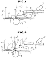
- an image recording apparatus includes a recording head 1 and a guide plate 2 in a known manner.
- the image recording apparatus take the form of an ink-jet printer and the recording head 1 takes the form of an ink-jet printhead.
- the guide plate 2 is arranged in a parallel spaced relationship with respect to the recording head 1 to guide paper sheets 8 in a predetermined direction as indicated by an arrow A.
- a paper conveyer includes a paper conveying roller 3 and a pinch roller 4.
- the roller 3 is arranged upstream of the guide plate 2 with respect to a flow of paper sheets 8 conveyed through a paper carrier path within the image recording apparatus, which paper carrier path the guide plate 2 forms a part of.
- the roller 3 has a fixed axis for rotation thereabout.
- the pinch roller 4 is supported by a roller support 5 for rotation about a pinch roller axis that is displaceable.
- the roller support 5 is displaceable from a first or home position as illustrated in Fig. 1 to a second position as illustrated in Fig. 2.
- a lock lever 6 is pivoted.
- a rotary cam 7 actuates the lock lever 6 between a lock position as illustrated in Fig. 1 and a release position as illustrated by the broken line in Fig. 2.
- the lock lever 6 has a lock tooth 9.
- the lock tooth 9 is adapted to engage a first notch 10 to hold the roller support 5 in the home position of Fig. 1 or a second notch 11 to hold the roller support 5 in the second position of Fig. 2.
- the roller support 5 is formed with the notches 10 and 11.
- the roller support 5 keeps the roller 4 in an exit position on the roller 3 so as to provide a state wherein, as it leaves the rollers, paper 8 is deflected towards the surface of the guide plate 2.
- This arrangement insures that the paper sheet 8 is received by the guide plate 2 in an appropriate spaced parallel relation with respect to a nozzle surface 12 of the recording head 1 without causing any partial separation from the surface of the guide plate 2.
- the axis of the roller 4 is displaced towards the guide plate 2 from the plane 13, including the axis of the roller 3, normal to the paper feeding direction C by a predetermined amount.
- This amount may be expressed in terms of a distance X between the normal plane 13 including the axis of the roller 3 and a normal plane 14 including the axis of the roller 4.
- this distance X ranges from 10 mm to 20 mm.
- the lock lever 6 is spring biased counterclockwise as viewed in Figs. 1 and 2. Viewing in Fig. 2, rotating the cam 7 counterclockwise towards a position as illustrated by the broken line causes the lock lever 6 to pivot clockwise from a lock position as illustrated by the fully drawn line to a release position as illustrated by the broken line. This clockwise pivot motion causes the lock tooth 9 to disengage from the notch 10 or 11 thereby to allow the roller support 5 to displace.
- a pivot pin and an elongate hole receiving the pivot pin cooperate with each other to define limits of movement of the roller support 5.
- the pivot pin may be integrally formed on the roller support 5 and the elongate hole may be formed through a frame of the image recording apparatus.
- the home position of the roller support 5 is defined by engagement of the pivot pin with one end of the elongate hole.
- the second position of the roller support 5 is defined by engagement of the pivot pin with the opposite end of the elongate hole.
- the pivot pin and elongate hole arrangement permits the weight of the roller support 5 to keep the roller 4 in frictional contact with the roller 3.
- the roller 4 is reluctant to rotate about its axis.
- counterclockwise rotation of the roller 3 causes the axis of the roller 4 to orbit about the axis of the roller 3 from the entrance position (Fig. 1) to the exit position (Fig. 2) to move the roller support 5 from the home position to the second position.
- clockwise rotation of the roller 3 causes the axis of the roller 4 to orbit from the exit position to the entrance position.
- rotation of the roller 3 causes the roller 4 to rotate about its axis.
- the axis of the roller 4 held in the entrance position see Fig.
- the image recording apparatus includes a system for detecting presence of paper sheet 8 within the rollers 3 and 4.
- the detecting system employs a sensor that uses a first beam of light passing through a portion of the paper carrier path immediately downstream of the plane 13 and a second beam of light passing through a portion of the paper carrier path immediately downstream of the plane 14.
- the detecting system When the first beam of light is interrupted by the passage of paper sheet 8, the detecting system generates a first pulse.
- the second beam of light is interrupted by the passage of paper sheet 8, the detecting system generates a second pulse.
- the leading edge of the first pulse is indicative of first moment at which the leading end of paper sheet 8 has passed through the plane 13.
- the trailing edge of the second pulse is indicative of second moment at which the trailing end of the paper sheet 8 has passed through the plane 14.
- the outputs of the detecting system are fed to a controller, not shown.
- the controller inputs information from the outputs of the detecting system as to the first moment when paper sheet 8 has entered the rollers 3 and 4 and the second moment when the paper sheet 8 has left the rollers 3 and 4.
- the controller outputs a cam drive signal to a driver for the cam 7.
- the cam driver rotates the cam 7 counterclockwise from the position shown in Fig. 1 to the position drawn by the broken line in Fig. 2 to disengage the lock tooth 9 from the notch 10 of the roller support 5.
- the cam 7 returns to take the position drawn by the fully drawn line in Fig. 1 owing to the action of the spring biasing the lock lever 6.
- the roller 3 rotates counterclockwise to urge the roller 4 and the roller support 5 to move toward the guide plate 2
- the roller support 5 moves toward the guide plate 2 immediately after the disengagement of the lock tooth 9 out of the notch 10.
- the lock tooth 9 disengages from the notch 10, it fails to align with the notch 10 so that even if the lock lever 6 returns toward the position as shown in Fig. 1, the lock tooth 9 will not enter the notch 10. However, the lock tooth 9 engages the notch 11 when the roller 4 and the roller support 5 take the position as illustrated in Fig. 2.
- the controller outputs cam drive signal to the cam driver and a roller reverse drive signal to a driver for the paper conveying roller 3.
- the cam driver rotates the cam 7 counterclockwise to the position drawn by the broken line in Fig. 2 to disengage the lock tooth 9 from the notch 11 of the roller support 5.
- the paper conveying roller driver rotates the roller 3 clockwise for a predetermined period of time, thus urging the roller 4 and roller support 5 for movement toward the position as illustrated in Fig. 1.
- the lock tooth 9 engages the notch 10.
- the roller 3 stops rotating clockwise.
Landscapes
- Engineering & Computer Science (AREA)
- Mechanical Engineering (AREA)
- Delivering By Means Of Belts And Rollers (AREA)
- Handling Of Cut Paper (AREA)
- Feeding Of Articles By Means Other Than Belts Or Rollers (AREA)
Applications Claiming Priority (3)
| Application Number | Priority Date | Filing Date | Title |
|---|---|---|---|
| JP8308797A JP2859226B2 (ja) | 1996-11-20 | 1996-11-20 | 用紙搬送装置 |
| JP30879796 | 1996-11-20 | ||
| JP308797/96 | 1996-11-20 |
Publications (3)
| Publication Number | Publication Date |
|---|---|
| EP0844535A2 true EP0844535A2 (fr) | 1998-05-27 |
| EP0844535A3 EP0844535A3 (fr) | 1999-04-21 |
| EP0844535B1 EP0844535B1 (fr) | 2003-04-16 |
Family
ID=17985431
Family Applications (1)
| Application Number | Title | Priority Date | Filing Date |
|---|---|---|---|
| EP97250347A Expired - Lifetime EP0844535B1 (fr) | 1996-11-20 | 1997-11-18 | Appareil d'enregistrement d'images avec un dispositif de transport de feuilles |
Country Status (4)
| Country | Link |
|---|---|
| US (1) | US6042112A (fr) |
| EP (1) | EP0844535B1 (fr) |
| JP (1) | JP2859226B2 (fr) |
| DE (1) | DE69720920T2 (fr) |
Families Citing this family (6)
| Publication number | Priority date | Publication date | Assignee | Title |
|---|---|---|---|---|
| JP2003025664A (ja) * | 2001-07-16 | 2003-01-29 | Canon Inc | 記録装置 |
| US7455295B2 (en) * | 2005-08-08 | 2008-11-25 | Hewlett-Packard Development Company, L.P. | Nip pressure |
| JP2008213290A (ja) * | 2007-03-05 | 2008-09-18 | Canon Inc | 記録装置 |
| JP4985801B2 (ja) * | 2010-02-26 | 2012-07-25 | Necアクセステクニカ株式会社 | 原稿読取装置 |
| JP5843521B2 (ja) * | 2011-08-19 | 2016-01-13 | キヤノン株式会社 | 搬送装置及び記録装置 |
| JP5997634B2 (ja) * | 2013-03-19 | 2016-09-28 | 株式会社Pfu | 媒体供給装置 |
Family Cites Families (10)
| Publication number | Priority date | Publication date | Assignee | Title |
|---|---|---|---|---|
| US2974952A (en) * | 1956-06-19 | 1961-03-14 | Zeuthen & Aagaard As | Registering mechanism for the accurate feed of sheets of paper to a printing device, particularly to duplicating machines |
| GB1471657A (en) * | 1974-09-13 | 1977-04-27 | Bowater Packaging Ltd | Carton blank feed apparatus |
| JPS5829166A (ja) * | 1981-08-13 | 1983-02-21 | Sony Corp | 記録再生装置のモ−ド切換装置 |
| JPH07115514B2 (ja) * | 1987-05-13 | 1995-12-13 | 沖電気工業株式会社 | 印字装置の媒体給送装置 |
| JP2994392B2 (ja) * | 1988-10-07 | 1999-12-27 | キヤノン株式会社 | 記録装置 |
| JPH0483650U (fr) * | 1990-11-29 | 1992-07-21 | ||
| JPH04288268A (ja) * | 1991-03-18 | 1992-10-13 | Canon Inc | 記録装置 |
| JPH04365733A (ja) * | 1991-06-12 | 1992-12-17 | Ricoh Co Ltd | 給紙装置 |
| JPH05162885A (ja) * | 1991-12-17 | 1993-06-29 | Fujitsu Ltd | 用紙搬送装置 |
| US5351945A (en) * | 1992-05-30 | 1994-10-04 | Mita Industrial Co., Ltd. | Overlapped transfer-preventing mechanism |
-
1996
- 1996-11-20 JP JP8308797A patent/JP2859226B2/ja not_active Expired - Lifetime
-
1997
- 1997-11-15 US US08/971,232 patent/US6042112A/en not_active Expired - Fee Related
- 1997-11-18 EP EP97250347A patent/EP0844535B1/fr not_active Expired - Lifetime
- 1997-11-18 DE DE69720920T patent/DE69720920T2/de not_active Expired - Fee Related
Also Published As
| Publication number | Publication date |
|---|---|
| US6042112A (en) | 2000-03-28 |
| DE69720920T2 (de) | 2004-02-26 |
| DE69720920D1 (de) | 2003-05-22 |
| JPH10147450A (ja) | 1998-06-02 |
| EP0844535A3 (fr) | 1999-04-21 |
| JP2859226B2 (ja) | 1999-02-17 |
| EP0844535B1 (fr) | 2003-04-16 |
Similar Documents
| Publication | Publication Date | Title |
|---|---|---|
| US6135446A (en) | Aligning device | |
| US20100066782A1 (en) | Printing apparatus and printing method | |
| US5897259A (en) | Paper feeding unit for apparatus using printer head | |
| US6042112A (en) | Paper conveyer for image recording apparatus | |
| US6089773A (en) | Print media feed system for an ink jet printer | |
| US20050200681A1 (en) | Paper discharge mechanism for a printer, and a printer | |
| US7258335B2 (en) | Eliminating drag of media sensor in printer media transport | |
| US5094554A (en) | Addressing machine | |
| EP0480719A2 (fr) | Machine pour adresser | |
| US8926089B2 (en) | Arrangement to print to strip-like print media | |
| US6655679B2 (en) | Input converger for hardcopy devices | |
| EP1634714B1 (fr) | Méthode d'impression d'un substrat et une imprimante à jet d'encre adaptée à cette méthode | |
| US6474387B1 (en) | Sorting device | |
| US5779234A (en) | Printer sheet discharge method | |
| KR20060063202A (ko) | 레지스트레이션장치 및 이를 채용한 화상형성장치 | |
| JPH01203138A (ja) | 画像形成装置 | |
| US10662011B2 (en) | Media transport | |
| US20060071390A1 (en) | Speed mode for printer media transport | |
| US5810492A (en) | Printer and print start method therefore | |
| US6945524B2 (en) | Card singularization gate | |
| NL1027001C2 (nl) | Inkjet printer. | |
| US4666322A (en) | Record carrier feed device | |
| US6206500B1 (en) | Printer having a guide plate for transporting waste ink | |
| GB2302314A (en) | Resilience in mounting between ink cartridge and print-head carriage. | |
| JPH05261994A (ja) | シート搬送装置 |
Legal Events
| Date | Code | Title | Description |
|---|---|---|---|
| PUAI | Public reference made under article 153(3) epc to a published international application that has entered the european phase |
Free format text: ORIGINAL CODE: 0009012 |
|
| AK | Designated contracting states |
Kind code of ref document: A2 Designated state(s): DE GB |
|
| PUAL | Search report despatched |
Free format text: ORIGINAL CODE: 0009013 |
|
| AK | Designated contracting states |
Kind code of ref document: A3 Designated state(s): AT BE CH DE DK ES FI FR GB GR IE IT LI LU MC NL PT SE |
|
| 17P | Request for examination filed |
Effective date: 19990518 |
|
| AKX | Designation fees paid |
Free format text: DE GB |
|
| 17Q | First examination report despatched |
Effective date: 20011018 |
|
| GRAH | Despatch of communication of intention to grant a patent |
Free format text: ORIGINAL CODE: EPIDOS IGRA |
|
| RTI1 | Title (correction) |
Free format text: IMAGE RECORDING APPARATUS WITH A PAPER CONVEYER |
|
| GRAH | Despatch of communication of intention to grant a patent |
Free format text: ORIGINAL CODE: EPIDOS IGRA |
|
| RIN1 | Information on inventor provided before grant (corrected) |
Inventor name: IZUMI, NAOYUKI |
|
| GRAA | (expected) grant |
Free format text: ORIGINAL CODE: 0009210 |
|
| AK | Designated contracting states |
Designated state(s): DE GB |
|
| REG | Reference to a national code |
Ref country code: GB Ref legal event code: FG4D |
|
| REF | Corresponds to: |
Ref document number: 69720920 Country of ref document: DE Date of ref document: 20030522 Kind code of ref document: P |
|
| PLBE | No opposition filed within time limit |
Free format text: ORIGINAL CODE: 0009261 |
|
| STAA | Information on the status of an ep patent application or granted ep patent |
Free format text: STATUS: NO OPPOSITION FILED WITHIN TIME LIMIT |
|
| 26N | No opposition filed |
Effective date: 20040119 |
|
| PGFP | Annual fee paid to national office [announced via postgrant information from national office to epo] |
Ref country code: GB Payment date: 20061115 Year of fee payment: 10 |
|
| PGFP | Annual fee paid to national office [announced via postgrant information from national office to epo] |
Ref country code: DE Payment date: 20061116 Year of fee payment: 10 |
|
| GBPC | Gb: european patent ceased through non-payment of renewal fee |
Effective date: 20071118 |
|
| PG25 | Lapsed in a contracting state [announced via postgrant information from national office to epo] |
Ref country code: DE Free format text: LAPSE BECAUSE OF NON-PAYMENT OF DUE FEES Effective date: 20080603 |
|
| PG25 | Lapsed in a contracting state [announced via postgrant information from national office to epo] |
Ref country code: GB Free format text: LAPSE BECAUSE OF NON-PAYMENT OF DUE FEES Effective date: 20071118 |