EP0844545A2 - Une méthode pour générer et changer l'échelle des profils de vitesse pour portes de cabines d'ascenseur - Google Patents
Une méthode pour générer et changer l'échelle des profils de vitesse pour portes de cabines d'ascenseur Download PDFInfo
- Publication number
- EP0844545A2 EP0844545A2 EP97309428A EP97309428A EP0844545A2 EP 0844545 A2 EP0844545 A2 EP 0844545A2 EP 97309428 A EP97309428 A EP 97309428A EP 97309428 A EP97309428 A EP 97309428A EP 0844545 A2 EP0844545 A2 EP 0844545A2
- Authority
- EP
- European Patent Office
- Prior art keywords
- time
- doors
- profile
- versus time
- elevator car
- Prior art date
- Legal status (The legal status is an assumption and is not a legal conclusion. Google has not performed a legal analysis and makes no representation as to the accuracy of the status listed.)
- Granted
Links
Images


Classifications
-
- B—PERFORMING OPERATIONS; TRANSPORTING
- B66—HOISTING; LIFTING; HAULING
- B66B—ELEVATORS; ESCALATORS OR MOVING WALKWAYS
- B66B13/00—Doors, gates, or other apparatus controlling access to, or exit from, cages or lift well landings
- B66B13/02—Door or gate operation
- B66B13/14—Control systems or devices
- B66B13/143—Control systems or devices electrical
-
- G—PHYSICS
- G05—CONTROLLING; REGULATING
- G05B—CONTROL OR REGULATING SYSTEMS IN GENERAL; FUNCTIONAL ELEMENTS OF SUCH SYSTEMS; MONITORING OR TESTING ARRANGEMENTS FOR SUCH SYSTEMS OR ELEMENTS
- G05B19/00—Program-control systems
- G05B19/02—Program-control systems electric
- G05B19/18—Numerical control [NC], i.e. automatically operating machines, in particular machine tools, e.g. in a manufacturing environment, so as to execute positioning, movement or co-ordinated operations by means of program data in numerical form
- G05B19/416—Numerical control [NC], i.e. automatically operating machines, in particular machine tools, e.g. in a manufacturing environment, so as to execute positioning, movement or co-ordinated operations by means of program data in numerical form characterised by control of velocity, acceleration or deceleration
Definitions
- the present invention relates to elevator car door systems and, more particularly, to the generation of velocity therefor.
- elevator car doors are driven into opened and closed positions by an electric motor.
- the elevator car doors usually couple to hoistway doors to drive hoistway doors into open and closed positions.
- the elevator car doors typically have to maintain certain velocities at the beginning of an operation, in the middle of the operation, and at the end of the operation. For example as the doors are opening, the initial velocity is relatively low to allow time for the elevator car doors to couple to the hoistway doors. After the two sets of doors are coupled, the doors accelerate to a higher velocity. The doors then decelerate toward the end of the opening operation to avoid slamming against a fixed stop.
- a number of methods are used to achieve the change in velocity of the elevator car doors during various operations.
- a conventional approach to changing the velocity of elevator car doors is to use resistors.
- the resistors are placed in series with a voltage source and a DC motor and adjusted to provide smaller or greater values of resistance.
- the greater resistance value corresponds to slower DC motor operation and to smaller generated velocity output.
- the converse is true for the smaller resistance values.
- this approach has a number of limitations.
- resistors cannot compensate for changes in friction or other loading on the doors.
- Third, resistors are adjusted by a trial and error method, which is time consuming and frequently lacks necessary precision.
- Another approach to varying the velocity of elevator car doors in modern closed loop systems includes software generated velocity profiles.
- the software dictates what the door velocity should be at a given time or distance.
- the velocity profiles are generated for each operation of the elevator car doors. This approach either results in a time lag for the doors to respond to a command or requires a powerful processor to generate profiles in real time.
- the transition from one velocity level to another is currently achieved by building in constant jerk (rate of change in acceleration) segments and constant acceleration segments of the profile.
- the constant jerk segments used to smooth the corners of the transition from constant velocity phase to constant acceleration phase of the doors, must match values of the velocity and acceleration where the constant jerk segments join the constant acceleration phase and the constant velocity phase. Matching the constant jerk segment with the constant acceleration phase and the constant velocity phase at numerous transition points takes a great deal of processor time.
- a door control system cannot cause the doors to follow the high frequency components of the profile if these frequency components are higher than the bandwidth of the control system. This can cause misoperation of the elevator car doors, such as the doors overshooting the final position and hitting the stops or exciting a resonant vibration frequency of the doors.
- the velocity profiles can be broken down to show the frequency content through a Fourier transform method.
- the profiles include low and high frequency components of velocity.
- the current method of providing constant jerk segments lowers the frequency content of the velocity profile by minimizing sharp corners, it is not known how much of the higher frequency content is attenuated and what is the frequency content of the profile. Aside from causing misoperation, the constant jerk method of generating a profile could result in very low frequency content and an associated increase in door operation time as compared to the optimum operation time.
- a position versus time profile for each type of operation of elevator car doors is stored as part of an initialization procedure of the elevator car doors and then scaled so that for every subsequent operation of elevator car doors, the elevator car doors follow either the stored position versus time profile or a scaled version thereof.
- the elevator car doors are either in a fully closed or fully opened position and must complete the entire opening or closing cycle, respectively, the elevator car doors follow the corresponding stored profile.
- the position versus time profile is scaled so that a scaled version of the position versus time profile can be followed by the elevator car doors.
- the door controller As a door controller receives a command to move the elevator car doors, the door controller also receives information about the initial position of the elevator car doors and how much time it should take to complete the operation.
- the stored position versus time profile is scaled based on the initial position of the elevator car doors and the time during which the elevator car doors must complete the operation.
- the present invention saves processor time because it uses stored profiles that are scaled rather than generating a profile in real time for every operation.
- the present invention also saves time and reduces the complexity of the software. Additionally, the present invention allows flexibility of tailoring each door operation for each specific floor without having to generate a new profile in real time and without sacrificing performance of the doors.
- an elevator system 10 includes an elevator car 12 and elevator car doors 14 which are driven into open and closed positions by an electric motor 16.
- the elevator car doors 14 typically couple to hoistway doors (not shown) by means of a coupling device 18 and pull the hoistway doors into open and closed positions.
- a door controller 20 is disposed on top of the elevator car 12 and is in communication with the electric motor 16. The door controller 20 also receives input from a door positioning system (not shown) and commands to move the elevator car doors 14.
- a closed loop feedback control system 26 governs movement of the elevator car doors 14.
- the closed loop feedback control system is embedded in the software of the door controller 20.
- the control system 26 includes position reference 28, X ref , as an input into the control system 26.
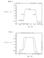
- a straight line velocity versus time profile is generated in the software of the door controller 20 as the elevator car door system is powered.
- the straight line velocity versus time profile represents the desired velocity values at certain times of the door operating function. For example, at the beginning of an opening door function, velocity values are relatively low to allow the hoistway doors to couple to the elevator car doors. Once the coupling is completed, the doors accelerate to a higher velocity value, shown in FIG. 3 as a velocity peak. The higher velocity value is maintained until the doors decelerate to a stop velocity. The lower velocity value is frequently necessary toward the end of a door operation to either decelerate the elevator car doors, or in the case of a closing operation tc allow the hoistway doors to decouple from the elevator car doors.
- the straight-line profiles are typically generated for each door function, such as opening, closing, reversing, or for different speeds required at various floors.
- the parameters that determine the shape of the straight-line velocity versus time profile can change. Such parameter changes require recalculation of a new straight-line velocity versus time profile.
- the straight-line velocity versus time profile is passed through a low pass finite impulse response (FIR) filter.
- the low pass filter attenuates high frequencies and ensures that the frequency content of the profile matches the bandwidth of a position feedback control system.
- the control system 26 has a one to two Hertz (1 to 2 Hz) position control bandwidth.
- the finite impulse response filter calculates the moving weighted average rounding the corners of the straight-line velocity versus time profile to ensure smooth transitions between different velocity values.
- a low pass finite impulse response filter a low pass infinite impulse response (IIR) filter could be used also.
- IIR infinite impulse response
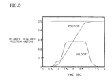
- the filtered velocity versus time profile is integrated to obtain a position versus time profile.
- another point is calculated and plotted as a point on the position versus time profile.
- the position versus time profile is generated in the preferred embodiment because the closed loop control system 26 is a position control system.
- the position versus time profile for each type of elevator car door operation is then stored in the RAM of the door controller 20.
- the position of the doors at the time of the command to move the doors is obtained from the positioning system providing input into the door controller 20 as to the position of the doors at the time the command to move the doors is received.
- the final position of the doors, X final is the final targeted position of the doors at the completion of the command.
- the total distance of the stored position versus time profile, X total is the total distance of the stored profile to be scaled and is a known parameter.
- a straight-line velocity versus time profile is generated as part of the initialization procedure.
- the velocity versus time profile is then passed through the low pass FIR filter.
- the filtered velocity versus time profile is then integrated into the position versus time profile.
- the profile is then stored for future use.
- the door controller 20 receives a command to move elevator car doors, the controller retrieves the stored position versus time profile for the appropriate operation.
- the door controller does not need to generate a profile for every command and take up valuable processor time.
- the door controller generates the scaling factors and scales the appropriate profile based on the initial position of the doors and the time during which the operations must be completed.
- each scaling factor equals one (1) and the software steps through the stored position versus time profile.
- the corresponding stored position versus time profile is scaled according to the above description. For example, if the doors are closing and at some intermediate point of the closing operation receive an opening command, the doors must travel only a portion of the total opening distance and must complete the task in a fraction of time. Therefore, the stored position versus time profile will be scaled and tailored for each deviant door operation.
- the present invention saves processor time because it uses stored profiles that are scaled rather than generating a profile in real time for every operation.
- the present invention also saves time and reduces the complexity of the software. Additionally, the present invention allows flexibility of tailoring each door operation for each specific floor without having to generate a new profile in real time and without sacrificing performance of the doors.
Landscapes
- Engineering & Computer Science (AREA)
- Automation & Control Theory (AREA)
- Human Computer Interaction (AREA)
- Manufacturing & Machinery (AREA)
- Physics & Mathematics (AREA)
- General Physics & Mathematics (AREA)
- Elevator Door Apparatuses (AREA)
- Power-Operated Mechanisms For Wings (AREA)
- Elevator Control (AREA)
Applications Claiming Priority (2)
| Application Number | Priority Date | Filing Date | Title |
|---|---|---|---|
| US08/754,457 US5804779A (en) | 1996-11-21 | 1996-11-21 | Method for generating and scaling velocity profiles for elevator car doors |
| US754457 | 1996-11-21 |
Publications (3)
| Publication Number | Publication Date |
|---|---|
| EP0844545A2 true EP0844545A2 (fr) | 1998-05-27 |
| EP0844545A3 EP0844545A3 (fr) | 1999-05-19 |
| EP0844545B1 EP0844545B1 (fr) | 2005-04-27 |
Family
ID=25034874
Family Applications (1)
| Application Number | Title | Priority Date | Filing Date |
|---|---|---|---|
| EP97309428A Expired - Lifetime EP0844545B1 (fr) | 1996-11-21 | 1997-11-21 | Une méthode pour générer et changer l'échelle des profils de vitesse pour portes de cabines d'ascenseur |
Country Status (7)
| Country | Link |
|---|---|
| US (1) | US5804779A (fr) |
| EP (1) | EP0844545B1 (fr) |
| JP (2) | JP4137206B2 (fr) |
| CN (1) | CN1091744C (fr) |
| DE (1) | DE69733114T2 (fr) |
| ID (1) | ID18932A (fr) |
| MY (1) | MY119302A (fr) |
Cited By (4)
| Publication number | Priority date | Publication date | Assignee | Title |
|---|---|---|---|---|
| US5864104A (en) * | 1996-07-03 | 1999-01-26 | Mitsubishi Denki Kabushiki Kaisha | Elevator door control apparatus |
| WO2007141560A3 (fr) * | 2006-06-02 | 2008-02-21 | Knorr Bremse Rail Sys Uk Ltd | Porte-écran de plateforme |
| EP4113222A1 (fr) * | 2021-06-28 | 2023-01-04 | Brabender GmbH & Co. KG | Procédé et unité de commande et/ou de régulation permettant de fournir une évolution temporelle d'un paramètre de mesure, ainsi que dispositif de mesure correspondant |
| US12139374B2 (en) * | 2018-11-12 | 2024-11-12 | Otis Elevator Company | Method and device for monitoring an elevator system |
Families Citing this family (15)
| Publication number | Priority date | Publication date | Assignee | Title |
|---|---|---|---|---|
| US6084375A (en) * | 1995-09-01 | 2000-07-04 | The Vision Limited Partnership | Method and apparatus for control of drive systems for cycle based processes |
| US20020178321A1 (en) * | 1998-11-25 | 2002-11-28 | Philip J. Calamatas | Programmable system including self locking memory circuit for a tristate data bus |
| US6445152B1 (en) * | 1999-11-24 | 2002-09-03 | Westinghouse Air Brake Co. | Door control system |
| FI117701B (fi) * | 2005-11-24 | 2007-01-31 | Kone Corp | Laitteisto ja menetelmä hissin oven ohjaamiseksi |
| JP5344887B2 (ja) * | 2008-10-27 | 2013-11-20 | 三菱電機株式会社 | エレベータのドア制御装置 |
| EP2298683A1 (fr) * | 2009-09-18 | 2011-03-23 | Inventio AG | Opérateur pour porte |
| CN102966283B (zh) * | 2012-11-14 | 2015-08-12 | 周裕佳 | 一种电动门及其缓冲控制方法 |
| WO2015022185A1 (fr) * | 2013-08-13 | 2015-02-19 | Inventio Ag | Système de surveillance d'une installation d'ascenseur |
| FI124545B (fi) * | 2013-09-26 | 2014-10-15 | Kone Corp | Menetelmä hissikomponentin liikkeen valvomiseksi sekä hissin turvajärjestely |
| CN104790862B (zh) * | 2015-02-16 | 2016-08-17 | 广西南宁市繁星科技有限公司 | 一种具有先启机构的自动开关锁及开关门的多扇门 |
| CN107010505A (zh) * | 2017-05-18 | 2017-08-04 | 厦门丰万达物联科技有限公司 | 基于加速度传感器的电梯轿厢门状态检测报警装置及方法 |
| JP7012488B2 (ja) * | 2017-09-11 | 2022-01-28 | 株式会社日立製作所 | エレベーターのドア制御装置ならびにエレベーターのドア駆動システム |
| JP7069888B2 (ja) * | 2018-03-15 | 2022-05-18 | 株式会社タダノ | クレーンおよびクレーンの制御方法 |
| CN111017687A (zh) * | 2019-11-22 | 2020-04-17 | 上海新时达电气股份有限公司 | 电梯控制方法、装置及计算机可读存储介质 |
| CN113697647A (zh) * | 2021-07-26 | 2021-11-26 | 杭州优迈科技有限公司 | 电梯门机的控制方法、装置、电子装置和存储介质 |
Family Cites Families (6)
| Publication number | Priority date | Publication date | Assignee | Title |
|---|---|---|---|---|
| US4342379A (en) * | 1979-12-27 | 1982-08-03 | Otis Elevator Company | Time controlled elevator door motion |
| US4776433A (en) * | 1988-01-25 | 1988-10-11 | Westinghouse Electric Corp. | Elevator door control system |
| ATE108416T1 (de) * | 1989-11-27 | 1994-07-15 | Inventio Ag | Verfahren und vorrichtung zur herabsetzung der einklemmgefahr bei automatischen türen. |
| US5378861A (en) * | 1993-02-16 | 1995-01-03 | Otis Elevator Company | Automatic setting of the parameters of a profile generator for a high performance elevator door system |
| JPH06250723A (ja) * | 1993-02-25 | 1994-09-09 | Komatsu Ltd | ロボットの振動低減装置 |
| JP3395278B2 (ja) * | 1993-09-16 | 2003-04-07 | ソニー株式会社 | 数値制御方法と数値制御装置 |
-
1996
- 1996-11-21 US US08/754,457 patent/US5804779A/en not_active Expired - Lifetime
-
1997
- 1997-10-28 MY MYPI97005086A patent/MY119302A/en unknown
- 1997-11-17 ID IDP973685A patent/ID18932A/id unknown
- 1997-11-20 CN CN97126298A patent/CN1091744C/zh not_active Expired - Fee Related
- 1997-11-21 EP EP97309428A patent/EP0844545B1/fr not_active Expired - Lifetime
- 1997-11-21 JP JP32022197A patent/JP4137206B2/ja not_active Expired - Fee Related
- 1997-11-21 DE DE69733114T patent/DE69733114T2/de not_active Expired - Lifetime
-
2007
- 2007-11-29 JP JP2007308586A patent/JP4198181B2/ja not_active Expired - Fee Related
Cited By (5)
| Publication number | Priority date | Publication date | Assignee | Title |
|---|---|---|---|---|
| US5864104A (en) * | 1996-07-03 | 1999-01-26 | Mitsubishi Denki Kabushiki Kaisha | Elevator door control apparatus |
| WO2007141560A3 (fr) * | 2006-06-02 | 2008-02-21 | Knorr Bremse Rail Sys Uk Ltd | Porte-écran de plateforme |
| US8183811B2 (en) | 2006-06-02 | 2012-05-22 | Knorr-Bremse Rail System (UK) Limited | Platform screen door |
| US12139374B2 (en) * | 2018-11-12 | 2024-11-12 | Otis Elevator Company | Method and device for monitoring an elevator system |
| EP4113222A1 (fr) * | 2021-06-28 | 2023-01-04 | Brabender GmbH & Co. KG | Procédé et unité de commande et/ou de régulation permettant de fournir une évolution temporelle d'un paramètre de mesure, ainsi que dispositif de mesure correspondant |
Also Published As
| Publication number | Publication date |
|---|---|
| EP0844545B1 (fr) | 2005-04-27 |
| JPH10157957A (ja) | 1998-06-16 |
| ID18932A (id) | 1998-05-20 |
| HK1010527A1 (en) | 1999-06-25 |
| JP4198181B2 (ja) | 2008-12-17 |
| CN1091744C (zh) | 2002-10-02 |
| DE69733114D1 (de) | 2005-06-02 |
| MY119302A (en) | 2005-04-30 |
| JP2008063149A (ja) | 2008-03-21 |
| DE69733114T2 (de) | 2005-09-29 |
| JP4137206B2 (ja) | 2008-08-20 |
| EP0844545A3 (fr) | 1999-05-19 |
| US5804779A (en) | 1998-09-08 |
| CN1185411A (zh) | 1998-06-24 |
Similar Documents
| Publication | Publication Date | Title |
|---|---|---|
| EP0844545B1 (fr) | Une méthode pour générer et changer l'échelle des profils de vitesse pour portes de cabines d'ascenseur | |
| EP0844544B1 (fr) | Une méthode pour générer des profils de vitesse pour portes de cabine d'ascenseur | |
| EP0477976A2 (fr) | Technique d'ajustage pour le système d'entraînement numérique d'un ascenseur | |
| EP0581578A1 (fr) | Système de commande de vitesse et de retard pour un essuie-glace | |
| JP2513450B2 (ja) | エレベ―タかごのドア駆動用リニアインダクションモ―タの駆動方法 | |
| EP0679603A2 (fr) | Méthode pour ajuster une porte d'ascenseur | |
| EP1842998B1 (fr) | Dispositif de commande pour ouverture/fermeture de la carrosserie d'un véhicule | |
| JP7012488B2 (ja) | エレベーターのドア制御装置ならびにエレベーターのドア駆動システム | |
| CN109895342A (zh) | 一种注塑机电动门开门距离的控制方法及系统 | |
| JP2001320891A (ja) | ドア制御装置およびドア制御装置の調整方法 | |
| EP0491201B1 (fr) | Procédé de production d'une référence de vitesse pour un moteur de grue | |
| HK1010527B (en) | A method for generating and scaling velocity profiles for elevator car doors | |
| JP2001302156A (ja) | エレベータのドア装置及びその改修工法 | |
| JP2023110430A (ja) | エレベーターのドア制御装置及びドア制御方法 | |
| HK1013198B (en) | A method for generating velocity profiles for elevator car doors | |
| JPH09309682A (ja) | エレベータかご扉装置 | |
| JPH08132369A (ja) | ロボット制御装置 | |
| KR100295481B1 (ko) | 엘리베이터도어재개방방법 | |
| JPH11113277A (ja) | モータ制御装置 | |
| KR20180037438A (ko) | 외란제어를 선택적으로 적용하는 엘리베이터 도어의 속도패턴 제어방법 | |
| JPH08338172A (ja) | パワーウインドの制御装置 | |
| JPH07319550A (ja) | 機械系制御装置 | |
| JPH0631150B2 (ja) | エレベ−タの扉制御方法 | |
| JPH04348807A (ja) | 数値制御装置における走行材料切断方法 | |
| JPH09322988A (ja) | 舞台装置の吊物運転制御装置 |
Legal Events
| Date | Code | Title | Description |
|---|---|---|---|
| PUAI | Public reference made under article 153(3) epc to a published international application that has entered the european phase |
Free format text: ORIGINAL CODE: 0009012 |
|
| AK | Designated contracting states |
Kind code of ref document: A2 Designated state(s): DE FR GB |
|
| AX | Request for extension of the european patent |
Free format text: AL;LT;LV;MK;RO;SI |
|
| PUAL | Search report despatched |
Free format text: ORIGINAL CODE: 0009013 |
|
| AK | Designated contracting states |
Kind code of ref document: A3 Designated state(s): AT BE CH DE DK ES FI FR GB GR IE IT LI LU MC NL PT SE |
|
| AX | Request for extension of the european patent |
Free format text: AL;LT;LV;MK;RO;SI |
|
| 17P | Request for examination filed |
Effective date: 19990622 |
|
| AKX | Designation fees paid |
Free format text: DE FR GB |
|
| 17Q | First examination report despatched |
Effective date: 20020131 |
|
| GRAP | Despatch of communication of intention to grant a patent |
Free format text: ORIGINAL CODE: EPIDOSNIGR1 |
|
| GRAS | Grant fee paid |
Free format text: ORIGINAL CODE: EPIDOSNIGR3 |
|
| GRAA | (expected) grant |
Free format text: ORIGINAL CODE: 0009210 |
|
| AK | Designated contracting states |
Kind code of ref document: B1 Designated state(s): DE FR GB |
|
| REG | Reference to a national code |
Ref country code: GB Ref legal event code: FG4D |
|
| REF | Corresponds to: |
Ref document number: 69733114 Country of ref document: DE Date of ref document: 20050602 Kind code of ref document: P |
|
| PLBE | No opposition filed within time limit |
Free format text: ORIGINAL CODE: 0009261 |
|
| STAA | Information on the status of an ep patent application or granted ep patent |
Free format text: STATUS: NO OPPOSITION FILED WITHIN TIME LIMIT |
|
| ET | Fr: translation filed | ||
| 26N | No opposition filed |
Effective date: 20060130 |
|
| PGFP | Annual fee paid to national office [announced via postgrant information from national office to epo] |
Ref country code: FR Payment date: 20141110 Year of fee payment: 18 Ref country code: GB Payment date: 20141119 Year of fee payment: 18 Ref country code: DE Payment date: 20141118 Year of fee payment: 18 |
|
| REG | Reference to a national code |
Ref country code: DE Ref legal event code: R119 Ref document number: 69733114 Country of ref document: DE |
|
| GBPC | Gb: european patent ceased through non-payment of renewal fee |
Effective date: 20151121 |
|
| REG | Reference to a national code |
Ref country code: FR Ref legal event code: ST Effective date: 20160729 |
|
| PG25 | Lapsed in a contracting state [announced via postgrant information from national office to epo] |
Ref country code: GB Free format text: LAPSE BECAUSE OF NON-PAYMENT OF DUE FEES Effective date: 20151121 Ref country code: DE Free format text: LAPSE BECAUSE OF NON-PAYMENT OF DUE FEES Effective date: 20160601 |
|
| PG25 | Lapsed in a contracting state [announced via postgrant information from national office to epo] |
Ref country code: FR Free format text: LAPSE BECAUSE OF NON-PAYMENT OF DUE FEES Effective date: 20151130 |