EP0845140B1 - Erschütterungsverminderung in gleitendem moderegelungsverfahren eines plattenantriebsstellgliedes - Google Patents
Erschütterungsverminderung in gleitendem moderegelungsverfahren eines plattenantriebsstellgliedes Download PDFInfo
- Publication number
- EP0845140B1 EP0845140B1 EP96928632A EP96928632A EP0845140B1 EP 0845140 B1 EP0845140 B1 EP 0845140B1 EP 96928632 A EP96928632 A EP 96928632A EP 96928632 A EP96928632 A EP 96928632A EP 0845140 B1 EP0845140 B1 EP 0845140B1
- Authority
- EP
- European Patent Office
- Prior art keywords
- signal
- actuator
- phase state
- phase
- gain
- Prior art date
- Legal status (The legal status is an assumption and is not a legal conclusion. Google has not performed a legal analysis and makes no representation as to the accuracy of the status listed.)
- Expired - Lifetime
Links
- 230000009467 reduction Effects 0.000 title description 3
- 230000001133 acceleration Effects 0.000 claims description 26
- 238000000034 method Methods 0.000 claims description 16
- 238000013500 data storage Methods 0.000 claims description 4
- 238000012545 processing Methods 0.000 description 35
- 230000006870 function Effects 0.000 description 13
- 230000004044 response Effects 0.000 description 13
- 238000010586 diagram Methods 0.000 description 4
- 230000008569 process Effects 0.000 description 4
- 230000007704 transition Effects 0.000 description 4
- 230000003044 adaptive effect Effects 0.000 description 3
- 230000009471 action Effects 0.000 description 2
- 230000000694 effects Effects 0.000 description 2
- 238000009499 grossing Methods 0.000 description 2
- 230000010354 integration Effects 0.000 description 2
- 230000004048 modification Effects 0.000 description 2
- 238000012986 modification Methods 0.000 description 2
- 230000035945 sensitivity Effects 0.000 description 2
- 238000013459 approach Methods 0.000 description 1
- 230000002238 attenuated effect Effects 0.000 description 1
- 230000008859 change Effects 0.000 description 1
- 244000145845 chattering Species 0.000 description 1
- 238000007796 conventional method Methods 0.000 description 1
- 238000005336 cracking Methods 0.000 description 1
- 238000013016 damping Methods 0.000 description 1
- 238000009795 derivation Methods 0.000 description 1
- 238000005516 engineering process Methods 0.000 description 1
- 230000004907 flux Effects 0.000 description 1
- 230000006872 improvement Effects 0.000 description 1
- 230000010355 oscillation Effects 0.000 description 1
- 230000002463 transducing effect Effects 0.000 description 1
Images






Classifications
-
- G—PHYSICS
- G11—INFORMATION STORAGE
- G11B—INFORMATION STORAGE BASED ON RELATIVE MOVEMENT BETWEEN RECORD CARRIER AND TRANSDUCER
- G11B5/00—Recording by magnetisation or demagnetisation of a record carrier; Reproducing by magnetic means; Record carriers therefor
- G11B5/48—Disposition or mounting of heads or head supports relative to record carriers ; arrangements of heads, e.g. for scanning the record carrier to increase the relative speed
- G11B5/58—Disposition or mounting of heads or head supports relative to record carriers ; arrangements of heads, e.g. for scanning the record carrier to increase the relative speed with provision for moving the head for the purpose of maintaining alignment of the head relative to the record carrier during transducing operation, e.g. to compensate for surface irregularities of the latter or for track following
- G11B5/596—Disposition or mounting of heads or head supports relative to record carriers ; arrangements of heads, e.g. for scanning the record carrier to increase the relative speed with provision for moving the head for the purpose of maintaining alignment of the head relative to the record carrier during transducing operation, e.g. to compensate for surface irregularities of the latter or for track following for track following on disks
- G11B5/59605—Circuits
- G11B5/59622—Gain control; Filters
-
- G—PHYSICS
- G11—INFORMATION STORAGE
- G11B—INFORMATION STORAGE BASED ON RELATIVE MOVEMENT BETWEEN RECORD CARRIER AND TRANSDUCER
- G11B5/00—Recording by magnetisation or demagnetisation of a record carrier; Reproducing by magnetic means; Record carriers therefor
- G11B5/48—Disposition or mounting of heads or head supports relative to record carriers ; arrangements of heads, e.g. for scanning the record carrier to increase the relative speed
- G11B5/54—Disposition or mounting of heads or head supports relative to record carriers ; arrangements of heads, e.g. for scanning the record carrier to increase the relative speed with provision for moving the head into or out of its operative position or across tracks
- G11B5/55—Track change, selection or acquisition by displacement of the head
- G11B5/5521—Track change, selection or acquisition by displacement of the head across disk tracks
- G11B5/5526—Control therefor; circuits, track configurations or relative disposition of servo-information transducers and servo-information tracks for control thereof
- G11B5/553—Details
- G11B5/5547—"Seek" control and circuits therefor
Definitions
- the present invention relates to computer technology and, more specifically, to controlling the read/write head actuator in a disk drive.
- a transducing head writes digital data onto the surface of a magnetic storage medium.
- the digital data serves to modulate the current in a read/write head coil so that a sequence of corresponding magnetic flux transitions are written onto the magnetic medium in a series of concentric data tracks.
- the magnetic medium again passes under the read/write head which transduces the magnetic transitions into pulses in an analog signal. These pulses are then decoded by read channel circuitry to reproduce the digital data.
- the read/write head is normally mounted on an actuator arm which is positioned by means of a voice coil motor (VCM).
- VCM voice coil motor
- a servo system controls the VCM, and thereby the head position, necessary for reading and writing information in response to requests from a computer to which the disk drive is connected.
- the servo system performs two functions: (1) a "seek” or “access” function in which the servo system moves the head to a selected track; and (2) when the head reaches the selected track, the servo system commences a "track following” or “tracking” function in which it accurately positions the head over a centerline of the track and maintains that position as successive portions of the track pass by the head.
- Servo control information embedded within the data provides inter-track head position information so that a head position error, indicative of a difference between the estimated head position and the desired head position, can be computed.
- the servo control system In response to the head position error, the servo control system generates a VCM control signal to align the head over the centerline of the selected track, thereby driving the head position error to zero.
- Conventional servo systems are typically linear controllers employing Proportional-Integral-Derivative (PID) feedback or state estimators.
- PID Proportional-Integral-Derivative
- Conventional adaptive linear controllers overcome these sensitivity problems by continuously re-programming the controller to compensate for the parameter variations and load disturbances.
- adaptive control systems can be overly complex and expensive to implement.
- adaptive linear controllers require notch filters to compensate for mechanical resonances. What is needed is a low cost, less complex solution to the sensitivity and resonance problems inherent in the control of a disk drive actuator.
- apparatus for use in at least one of reading and writing data recorded on a data storage medium by means of a read/write head whose position relative to the medium is adjustable by an actuator operated by a motor,
- a spin motor rotates a magnetic disk under a read/write head. Recorded on the magnetic disk are several concentric data tracks having servo information embedded thereon.
- Read channel circuitry connected to the read/write head, decodes the digitally recorded data and transmits the servo data to a state estimator.
- the state estimator processes the servo data to generate an actuator position signal that is subtracted from a reference actuator position to generate an actuator position error signal.
- a sliding mode controller responsive to the actuator position error signal, switches between positive and negative feedback gains (rather than maximum positive and negative values as in "bang-bang" control) in order to generate a motor control signal.
- the motor control signal is amplified and applied to a VCM connected to one end of an actuator having the read/write head attached to the other end.
- the VCM controls the motion of the actuator in order to position the read/write head over a selected track.
- the sliding mode controller is defined by two phase states: an actuator position error phase state and a actuator position error velocity phase state.
- the actuator position error phase state is the difference between an estimated actuator position and a desired actuator position (e.g., the difference between a current track the read/write head is positioned over and a selected new track).
- the actuator position error velocity phase state is the rate of change of the actuator position error and can be generated by differentiating the actuator position error or by a state estimator.
- the position error velocity is also the negative velocity of the actuator.
- the sliding mode controller By switching between positive and negative feedback gains, the sliding mode controller operates to drive the phase states toward a predetermined phase plane trajectory.
- the sliding mode controller is, therefore, a function of the phase states rather than the physical characteristics of the disk drive, and the control system is substantially insensitive to parametric variations and external load disturbances.
- the notch filters in conventional linear controllers used to compensate for mechanical resonances are not necessary in the sliding mode controller of the present invention. It is relatively simple and inexpensive to implement, and there is a well defined method for proving global stability.
- the phase plane trajectory is defined by four segments: a substantially parabolic acceleration segment that defines an acceleration of the actuator toward the selected track; a linear constant velocity segment that defines a constant velocity of the actuator toward the selected track; a substantially parabolic deceleration segment that defines a deceleration of the actuator toward the selected track; and a linear tracking segment that defines a tracking mode of the actuator.
- the sliding mode controller comprises switching logic, responsive to the phase states, for switching between the positive and negative feedback modes wherein the switching logic operates according to the current trajectory segment being followed by the phase states.
- the sliding mode controller further comprises a a processing block, also responsive to the phase states, for controlling the operating mode of the switching logic by determining which trajectory segment ⁇ the phase states are to follow.
- the sliding mode controller In order to reduce noise caused by switching between the negative and positive feedback gains, the sliding mode controller generates the motor control signal using only the actuator position error velocity phase state during seek operations. This reduces the magnitude of the control signal, and thereby the amount of switching in the system, but also requires an initial error velocity reference signal to start the actuator moving in the correct direction. Once the actuator substantially reaches the selected track, the sliding mode controller switches to a tracking mode and generates the motor control signal using both the actuator position error and actuator position error velocity phase states. The actuator position error is also integrated and added to the motor control signal in order to drive the steady state error to zero.
- the sliding mode controller is responsive to an actuator position error, velocity error, and acceleration phase states.
- the velocity error is generated by subtracting an estimated velocity from a reference velocity, where the reference velocity is computed as a function of the actuator position error.
- control signal is generated proportional to an integral of sgn( ⁇ ),
- control signal is smoothed to attenuate the high frequency components that can generate electromagnetic and/or acoustic emissions.
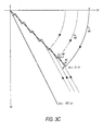
- Figure 3C illustrates the operation of the sliding mode controller in driving the phase states toward a predetermine linear phase trajectory during a forward seek to a new track.
- Figure 3D illustrates the affect of changing the slope of the linear phase trajectory in Figure 3C in order to extend the sliding mode.
- Figure 3E illustrates a phase plane trajectory which covers the whole region of excursion thereby eliminating any linear mode of operation that may be sensitive to parameter variations.
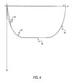
- Figure 4 illustrates the preferred phase plane trajectory of the present invention.
- Figure 5 illustrates the VCM controller as a second order system having a position error and position error velocity phase state.
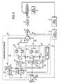
- Figure 6 is a detailed diagram of the disk drive control system wherein the sliding mode controller is responsive to a position error and a position error velocity phase state.
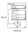
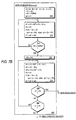
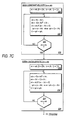
- FIGS 7A, 7B, and 7C are flow charts that describe the operation of the sliding mode controller with reference to Figure 6.
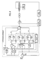
- Figure 8 is a detailed block diagram of a sliding mode controller is responsive to an actuator position error, velocity error, and acceleration phase states.
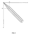
- Figure 9 illustrates the converging boundary layer around the sliding mode phase state trajectory.
- Figure 10 shows an integrator for integrating sgn ( ⁇ ) in order to smooth the motor control signal.
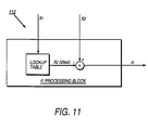
- Figure 11 is the preferred lookup table embodiment of the ⁇ processing block.
- FIG. 1 is an overview of the disk drive control system of the present invention.
- a spin motor 2 spins a magnetic disk 4 with computer data recorded thereon under a read/write head 6.
- An actuator 8 positions the read/write head 6 over a selected track, and a Voice Coil Motor (VCM) 10 controls the motion of the actuator 8 .
- VCM Voice Coil Motor
- Read channel circuitry 12 connected to receive the analog signal from the read/write head 6 , decodes the digital data recorded on the magnetic disk and transmits servo information to a state estimator 14.
- the state estimator 14 models the VCM control system in order to generate an estimated actuator position 16 that is subtracted from a reference actuator position 18 at adder 20 to produce an actuator position error X 1 22.
- the reference actuator position 18 is the position of a selected track at which data is to be written or read.
- a sliding mode controller 26 responsive to the actuator position error X 1 22, computes an acceleration motor control signal U 28, amplified by amplifier 30, and applied to the VCM 10 to position the read/write head over the selected track.
- the state estimator 14 also processes the motor control signal U 28 to generate the estimated actuator position 16.
- the state estimator 14 filters out errors in the servo position information caused by noise in the recording channel.
- the state estimator 14 can also replace the differentiator 102 in order to generate the actuator position error velocity phase state X2.
- State estimators are well known in the prior art such as described in U.S. Patent No. 4,679,103, the disclosure of which is hereby expressly incorporated by reference. There are also other well known techniques other than state estimators for generating the actuator phase states for use by the present invention.
- each data track comprises a plurality of sectors 36 and a plurality of servo fields 38 embedded therein.
- the servo fields 38 comprise track number information 40 processed by the state estimator 14 to generate the estimated actuator position 16 while seeking the selected track.
- the state estimator 14 processes the track number 40 and the servo burst information 42 in the servo fields to align the head over the centerline of the selected track while writing and reading data.
- Servo bursts comprise a plurality of pulses recorded at precise locations adjacent to the track centerline. The magnitude of these servo burst pulses sensed by the read/write head indicates the off track position of the head.
- FIG. 3A Shown is an example second order system 44 controlled by an example sliding mode controller 45 that switches 46 between a positive gain 47 and negative gain 48 not necessarily equal in magnitude.
- a position error X 1 49 is generated at the output of adder 50 by subtracting an estimated position 51 of the controlled system from a desired position reference command 52.
- the position error X 1 49 is multiplied by the positive gain 47 or the negative gain 48 depending on the state of switch 46 to generate an acceleration command U 53 as the input to the controlled system 44.
- the output of integrator 54 is the velocity of the controlled system 44 which is also the negative of the position error velocity -X 2 55.
- Equation (1) Asin( Kt + ⁇ )
- X 2 ⁇ K Acos ( Kt + ⁇ )
- X 1 2 A 2 + X 2 2 KA 2 1
- the phase plane plot of equation (4) is a set of ellipses with eccentricities A and ⁇ K A as illustrated in Figure 3B.
- the state space equation in positive feedback is:
- the solution to equation (5) is:
- X 1 B 1e ⁇ K t + B 2e - ⁇ K t
- X 2 ⁇ K B 1e ⁇ K t - K B 2e - ⁇ K t
- X 1 2 4 B 1 B 2 - X 2 2 4 KB 1 B 2 1
- the phase plane plot of equation (7) is a set of hyperbolas with two asymptotes as shown in Figure 3B.
- the switching operation is understood with reference to Figure 3C where the predetermined third phase state trajectory is shown as a linear segment 60.
- the initial actuator position error is at point A, and the control system is initially switched to select the positive gain (i.e., negative feedback).
- the phase states follow the arc trajectory 64 of the negative feedback mode.
- the sliding mode controller switches to the negative gain and the phase states begin to follow the hyperbola trajectory 66 of the positive feedback mode.
- the controller switches back to the positive gain to drive the phase states along arc 68 back toward the third phase state trajectory 60 .
- phase states slide along the linear segment 60 toward the origin of the phase plane.
- the system switches to a tracking mode where the sliding mode controller 26 repeatedly switches between positive and negative feedback in order to keep the phase states near the origin of the phase plane, thereby keeping the read/write head 6 aligned over the centerline of the selected track.
- Equation (8) is the average response of the system along the sliding line and it is substantially unaffected by variations in the parameter K or by external load disturbances. Consequently, it is not necessary to know the exact parameters of the system in order to determine the value for K. Equation (8), together with the existence Equation (11) below, prove that the system is globally stable within the sliding mode region.
- the sliding mode controller determines when to switch between the positive and negative gains by observing the phase state values.
- the sliding mode controller switches to the positive gain when ⁇ X 1 >0 and to the negative gain when ⁇ X 1 ⁇ 0 in order to drive the phase states toward the linear phase state trajectory.
- Equation (11) is known as the existence equation and is used to determine values for the positive and negative gains.
- the linear sliding line trajectory 60 of Figure 3C has the disadvantage in that it initially operates in a linear feedback mode, and the initial arc trajectory 64 may drift due to parameter variation and external load disturbance. This problem is reduced by extending the sliding mode region of operation.
- a phase trajectory adjustor can continuously adjust the slope of the linear segment as shown in Figure 3D. After the phase states reach the first sliding line 65 and follow it for a predetermined amount of time, the phase trajectory adjustor increases the slope to sliding line 67 by increasing the constant C.
- the system operates in a linear mode (non-sliding mode) only during the inter-segment transitions. Eventually, the slope is increased to a predetermine maximum at sliding line 69 at which point the phase states slide along line 69 toward the origin of the phase plane.
- C 2 is constrained to 0 ⁇ C 2 ⁇ K , but all three segments are also constrained by the maximum acceleration, constant velocity, and deceleration limits of the VCM 10 .
- This trajectory comprises a substantially parabolic acceleration segment ⁇ 1 80, a linear constant velocity segment ⁇ 2 82, a second substantially parabolic deceleration segment ⁇ 3 84, and a linear deceleration segment ⁇ 4 86:
- ⁇ 1 C 1 •X 2 2 + X 1 - X 1I ;
- ⁇ 2 X 2 - X 2I ;
- ⁇ 3 -C 2 •X 2 2 + X 1 ;
- ⁇ 4 X 2 + C 3 •X 1 ;
- Figure 5 shows the disk actuator control system modeled as a second order plant.
- the output of the sliding mode controller U 28 is amplified 30 and input into the VCM 10 .
- the parameters of the VCM 10 are:
- the position error phase state X 1 22 is observed at the output of adder 20, and the position error velocity phase state X 2 is observed as the negative of the VCM 10 velocity 92.
- the disk drive actuator control system of the present invention operates optimum with the position error velocity X 2 as the only control signal during a seek since the position error X 1 is initially much larger than the position error velocity X 2 . Removing the position error X 1 from the feedback loop during seeks reduces the amount of switching noise. When the phase states reach a predetermined point on the phase trajectory, the system switches the position error X 1 phase state back into the control loop.
- FIG. 6 is a detailed diagram of the disk drive actuator sliding mode control system.
- the actuator position error X 1 22 is input into the sliding mode controller 26, and a differentiator 102 differentiates the actuator position error X 1 22 to generate the actuator position error velocity signal X 2 100.
- the state estimator 14 generates the position error velocity X 2 .
- Two switching gain circuits 104 and 106 multiply the position error ⁇ X 1 130 and error velocity ⁇ X 2 132 control signals, respectively.
- Multipliers 108 and 110 responsive to the phase states ⁇ X 1 and X 2 and the current trajectory segment ⁇ i , control the switching operation of the gain circuits.
- a ⁇ processing block 112 responsive to the phase states X 1 and X 2 , implements the trajectory segment switching logic to determine which segment ⁇ i of the phase state trajectory the phase states are to follow.
- the operation of the ⁇ processing block 112, the integrator 116 , the reference error velocity generator 114, and multiplexers 118, 120, and 122, are discussed in detail bellow.
- the gain values ⁇ i , ⁇ i , ⁇ i and ⁇ i in switching gain blocks 104 and 106 are programmably set to appropriate values according to the current trajectory segment being followed by the phase states. Also, the gain values are programmed to predetermined values depending on whether the controller is executing a forward or reverse seek. Using the existence equation (11) and the phase state trajectory equations (13), (14), (15) and (16), the gain values for each segment of the phase state trajectory shown in Figure 4 can now be computed.
- the sliding mode controller initializes various parameters 210.
- the position error phase state X 1 22 is switched out of the sliding mode control.
- the ⁇ processing block 112 selects, over line 126, the ground plane as the output of multiplexer 122.
- -X 1 130 is set to zero in order to disable the switching action of multiplier 110 and to remove the contribution of ⁇ 1 from the computation of the VCM command U 28 at the output of adder 103 .
- the velocity phase state ⁇ X 2 132 is initialized to a predetermined value to ensure the actuator begins moving in the desired direction (i.e., moving in reverse toward the selected track).
- the ⁇ processing block 112 selects, over line 124, X 2 Ref 114 as the output of multiplexor 120.
- the ⁇ processing block 112 also selects, over line 126, the predetermined constant C 134 as the output of multiplexer 118 (the third input ⁇ 3 109 to adder 103 ).
- the function of the predetermined constant C 134 and the integrator 116 are discussed in further detail below.
- the sliding mode controller 26 continuously computes and outputs the VCM command signal U 28 at the output of adder 103.
- ⁇ 1 is updated according to equation (13) and ⁇ i 128 is assigned to ⁇ 1 .
- Multiplier 108 (which can be implemented as a simple XOR of the operand sign bits) multiplies ⁇ i by X 2 and switches gain block 104 to ⁇ i if the result is positive and to ⁇ i if the result is negative.
- Gain block 104 multiplies ⁇ X 2 132 (X 2 Ref 114 ) by the selected gain to generate ⁇ 2 .
- Adder 103 adds ⁇ 1 , ⁇ 2 , and ⁇ 3 to generate the VCM command U 28. Since ⁇ 1 is zero during acceleration and ⁇ 3 is insignificantly small, the VCM command signal U 28 is predominately equal to ⁇ 2 .
- Amplifier Kpa 30 amplifies the command signal U 28 and applies it to the VCM 10 .
- the read/write head 6 passes over the servo data of the next adjacent track and reads the corresponding track address.
- the read channel 12 decodes the crack address and transmits it to the state estimator 14 which, in response to the track address and the current VCM command 28, updates the actuator position signal 16.
- Adder 20 outputs the new position error X 1 22, and differentiator 102 computes the new velocity phase state X 2 100 as X 1 (N) - X 1 (N-1).
- the sliding mode controller 26 generates the VCM command signal U 28 in flow chart 218 as a function of the velocity phase state X 2 100.
- the ⁇ processing block 112 updates ⁇ 1 , ⁇ 2 , and ⁇ 3 according to equations (13), (14), and (15), respectively.
- the output ⁇ i 128 of ⁇ processing block 112 is assigned to ⁇ 1 .
- multiplier 108 sets the state of switching gain block 104 in order to drive X 1 and X 2 toward the ⁇ 1 80 phase trajectory.
- the next command U 28 is generated and applied to the VCM 10 to continue moving the actuator 8 toward the selected track.
- the ⁇ processing block 112 continuously checks the location of the phase states with respect to the acceleration trajectory ⁇ 1 80 to determine when to switch to the next trajectory segment.
- the next trajectory segment will either be the constant velocity segment ⁇ 2 82 or, if the seek distance is sufficiently short, the deceleration segment ⁇ 3 84.
- the ⁇ processing block 112 determines when to switch to the next trajectory. If ⁇ 1 ⁇ ⁇ 3 ? 220 is YES, then the ⁇ processing block 112 switches to the deceleration trajectory ⁇ 3 84. Else if ⁇ 1 ⁇ ⁇ 2 ? 222 is YES, then the ⁇ processing block 112 switches to the constant velocity trajectory ⁇ 2 82. If both 220 and 222 are NO, then the sliding mode controller 26 loops around and computes the next VCM command U 28 according to flow chart 218.
- the gain constants for switching gain blocks 104 and 106 are updated 228 to values corresponding to the constant velocity trajectory ⁇ 2 82 of Figure 4.
- the ⁇ processing block 112 updates ⁇ 2 and ⁇ 3 according to equations (14) and (15), respectively.
- the output ⁇ i 128 of ⁇ processing block 112 is assigned to ⁇ 2 .
- multiplier 108 sets the state of switching gain block 104 in order to drive X 1 and X 2 toward the ⁇ 2 82 phase trajectory.
- the next command U 28 is generated and applied to the VCM 10 to continue moving the actuator 8 toward the selected track.
- the ⁇ processing block 112 continuously checks the location of the phase states with respect to the constant velocity trajectory ⁇ 2 82 to determine when to switch to the deceleration trajectory segment ⁇ 3 84. If ⁇ 2 ⁇ ⁇ 3 ? 232 is YES, then the ⁇ processing block 112 switches to the deceleration trajectory ⁇ 3 84. Otherwise, the sliding mode controller 26 loops around and computes the next VCM command U 28 according to flow chart 230.
- the ⁇ processing block 112 updates ⁇ 3 and ⁇ 4 according to equations (15) and (16), respectively.
- the output ⁇ i 128 of ⁇ processing block 112 is assigned to ⁇ 3 .
- multiplier 108 sets the state of switching gain block 104 in order to drive X 1 and X 2 toward the ⁇ 3 84 phase trajectory.
- the next command U 28 is generated and applied to the VCM 10 to decelerate the actuator 8 toward the selected track.
- the ⁇ processing block 112 continuously checks the location of the phase states with respect to the deceleration trajectory ⁇ 3 84 to determine when to switch to the tracking trajectory segment ⁇ 4 86. If ⁇ 4 ⁇ ⁇ 3 ? 240 is YES, then the ⁇ processing block 112 switches to the tracking trajectory ⁇ 4 86. Otherwise, the sliding mode controller 26 loops around and computes the next VCM command U 28 according to flow chart 238.
- the read channel process the servo burst information 42 recorded adjacent to the selected track's centerline in order to generate an actuator 8 offset position relative to the centerline.
- the state estimator 14 In response to the offset position and the command signal U 28 , the state estimator 14 generates the estimated actuator position 16 which is subtracted from the reference selected crack position 18 to generate the position error X 1 22.
- the gain constants for switching gain blocks 104 and 106 are updated 202 to values corresponding co the tracking trajectory ⁇ 4 86 of Figure 4.
- the ⁇ processing block 112 selects via line 126 the output of integrator 116 as the output of multiplexor 118 (i.e., ⁇ 3 ).
- the ⁇ processing block 112 also switches the position error phase state X 1 22 back into the sliding mode computation, by selecting via line 126, as the output of multiplexer 122, the position error phase state X 1 22 as the input to multiplier 110. Again, the position error phase state X 1 22 is not used during seeks in order to reduce switching noise.
- the ⁇ processing block 112 updates ⁇ 4 according to equations (16).
- the output ⁇ i 128 of ⁇ processing block 112 is assigned to ⁇ 4 .
- multipliers 108 and 110 set the state of switching gain blocks 104 and 108, respectively, in order to drive X 1 and X 2 toward the ⁇ 4 86 phase trajectory.
- the next command U 28 is generated and applied to the VCM 10 to continue cracking the centerline of the selected track.
- biasing forces can cause the actuator 8 to have a steady state DC offset from the centerline.
- Typical biasing forces include the radial component of the windage caused by the rotating disks, tilt of the disk stack, biases in the flexible cables, and electrical offsets.
- an integrator 116 integrates the position error phase state X 1 22 and its output 109 is summed 103 into the output 28 of the sliding mode controller 26.
- the biasing forces do not vary with time, however, they do vary with the radial position of the actuator 8. Therefore, the steady state integration value 109 corresponding to the biasing forces for each track is stored in memory.
- the integrator 116 is disabled and the steady state integration value stored in memory corresponding to the selected new track is added 103 as a constant 134 to the control signal 28.
- the integrator 116 is re-enabled and its output added 103 back into the control signal 28.
- the sliding mode controller 26 operates as described in the flow charts of Figures 7A, 7B, and 7C except that the inequalities are reversed.
- the ⁇ processing block 112 can also adjust the slope of the linear phase trajectory segment as shown in Figure 3D.
- An alternative embodiment of the ⁇ processing block 112 would be to compare the position error and velocity phase states to values stored in a look up table where the stored values represent the phase plane trajectory shown in Figure 4.
- FIG 8. An other sliding mode controller is shown in Figure 8.
- the state space is defined in the plane (X v , X ⁇ ), where X v is an actuator velocity error phase state and X ⁇ is an actuator acceleration phase state.
- a reference velocity Vref is generated as a function of the position error X 1 corresponding to the velocity profiles ⁇ 1 80 and ⁇ 3 84 shown in Figure 4.
- the reference velocity generator can be implemented with a lookup table or with polynomial equations.
- An actuator velocity error phase state X v is generated by subtracting an estimated actuator velocity -X 2 from the reference velocity Vref.
- An actuator acceleration phase state X ⁇ is generated by taking the second derivative of the position error X 1 .
- Phase states X v and X ⁇ are multiplied by respective switching gain blocks to generate control signals ⁇ 2 and ⁇ 4 . As discussed with reference to Figures 6 and 7, control signal ⁇ 1 is disabled during seeks and ⁇ 3 is insignificantly small.
- the motor control signal U is a function of ⁇ 2 and ⁇ 4 during seek accelerate and seek decelerate.
- the sliding mode controller of Figure 8 operates as described in Figures 6 and 7 during seek at constant velocity and tracking.
- the ⁇ processing block 112 of the present invention can be implemented using a lookup table rather than switching between trajectory segments.
- the phase states can be used as an index into a lookup table in order to implement the phase state trajectory ⁇ .
- the sliding mode controller can provide further improvements in chatter reduction by defining a boundary layer around the phase state trajectory ⁇ . This is illustrated in Figure 9 which shows a linear segment for the phase state trajectory ⁇ having a boundary layer defined as an offset ⁇ added to ⁇ .
- the boundary layer reduces chatter by reducing the amount of switching in the system. Without the boundary layer, the switching gain blocks 104 and 106 of Figure 6 will switch every time the phase states cross the sliding line (i.e., every time ⁇ changes sign). The boundary layer results in hysteresis which causes the gain blocks to switch only after the phase states cross over the boundary line.
- the boundary layer offset ⁇ added to the phase state trajectory ⁇ is a predetermined constant until the phase states reach a predetermined value (X 1 c ,X 2 c ) at which time the offset ⁇ is computed as the sum of the phase states X 1 and X 2 so that the boundary layer converges to the origin of the phase plane, as shown in Figure 9, in order to prevent oscillations around the origin.
- the sliding mode controller can achieve still better chatter reduction by generating the VCM control signal U proportional to an integral of sgn( ⁇ ).
- the control signal is smoothed to attenuate the high frequency components that can generate electromagnetic and/or acoustic emissions.
- ⁇ i from ⁇ processing block 112 is input into an integrating block 101 which computes the following function:
- the output 128 of the integrating block 101 controls the state of switching gain blocks ⁇ 104,106 ⁇ and is also input into an absolute value function 111.
- the control signal at the output of adder 103 is then attenuated by the absolute value of the integrated sgn( ⁇ i ) through a multiplier 113 to generate the smoothed VCM control signal U.
- the sliding mode controller may be implemented in hardware or software, and higher order phase states could be used in place of, or in addition to, the particular phase states disclosed.
- the servo data can be recorded on a dedicated servo disk in a disk array.
Landscapes
- Moving Of The Head To Find And Align With The Track (AREA)
- Feedback Control In General (AREA)
- Moving Of Head For Track Selection And Changing (AREA)
Claims (17)
- Vorrichtung zur Verwendung beim Lesen und/oder Schreiben von auf einem Datenspeichermedium (4) gespeicherten Daten mittels eines Lese-/Schreibkopfes, dessen Position relativ zu dem Medium mittels eines von einem Motor (10) betätigten Aktuator (8) einstellbar ist, wobei die Vorrichtung versehen ist mit:dadurch gekennzeichnet, dass ferner vorgesehen sind:einem Gleitmodusregelgerät (26), das betätigbar ist, um ein Motorregelsignal (U) zur Verwendung beim Regeln des Motors auszugeben, wobei das Regelgerät versehen ist mit:einer Eingabeanordnung (12, 14, 20) zum Eingeben eines Aktuatorpositionsfehlersignals (X1), welches indikativ für die Differenz zwischen einer geschätzten Aktuatorposition und einer gewünschten Aktuatorposition ist;einer Erzeugungsanordnung (122, 120, 102), um aus dem Aktuatorpositionsfehlersignal Phasenstatussignale (∼X1, ∼X2) zu erzeugen, die eine Trajektorie in einem Statusraum bestimmen;einer Berechnungsanordnung (112), um aus den Phasenstatussignalen einen Parameter σ gemäß einer vorbestimmten Beziehung (σ1, σ2, σ3, σ4) zu berechnen, die eine Gleitlinie in dem Statusraum definiert;einer Regelanordnung, die den Wert des Parameters σ benutzt, um einen umschaltenden Verstärkerblock (106) so anzusteuern, dass die Verstärkung zwischen einer ersten und einer zweiten Verstärkung (α, β) umgeschaltet wird, wenn die Trajektorie die Gleitlinie schneidet, so dass die Verstärkung des Verstärkerblocks auf die Phasenstatussignale angewendet wird, um die Ausgabe eines Regelsignals (u) zu erreichen; undeiner Erzeugungsanordnung (103, 113) zum Erzeugen eines Motorregelsignals von dem Regelsignalausgang;
eine Integrationsanordnung (101) zum Integrieren des Parameters σ, um einen geglätteten Parameterwert zur Verwendung beim Ansteuern des umschaltenden Verstärkerblocks zu erhalten, sowie ein Multiplizierer (113) zum Multiplizieren des Regelsignals mit der Größe des geglätteten Parameterwerts, um dadurch Hochfrequenzkomponenten in dem Motorregelsignal abzuschwächen. - Vorrichtung nach Anspruch 1, bei welchem die Integrationsanordnung (101) betätigbar ist, um ein Vorzeichen der Phasenebenenvariable (sgn(σi)) zu integrieren.
- Vorrichtung nach Anspruch 2, versehen mit einer Absolutwertfunktionsanordnung (111), die betätigbar ist, um den Absolutwert des Ausgangs der Integrationsanordnung zu bilden und diesen Absolutwert an den Multiplizierer anzulegen.
- Vorrichtung nach Anspruch 1, wobei eines der Phasenstatussignale ein Aktuatorpositionsfehlergeschwindigkeitssignal (∼X2) ist, welches durch Differenzieren des Aktuatorpositionsfehlersignals erhalten wird.
- Vorrichtung nach einem der vorhergehenden Ansprüche, ferner versehen mit:(a) einem zweiten Eingang, der angeschlossen ist, um ein Aktuatorgeschwindigkeitsfehlersignal (Xv) zu erhalten;(b) einem zweiten umschaltenden Verstärkerblock (104), der betätigbar ist, um selektiv ein zweites Phasenstatussignal (132, ∼X2), welches proportional zu dem Aktuatorgeschwindigkeitsfehlersignal ist, mit einer dritten Verstärkung (γi) oder mit einer vierten Verstärkung (ζi) gemäß einem Wert einer zweiten Phasenebenenvariablen zu multiplizieren, die repräsentativ für den Status des zweiten Phasenstatussignals und eine zweite Phasenebenentrajektorie gemäß einer zweiten vorbestimmten Beziehung ist, um ein zweites proportionales Phasenstatussignal zu erzeugen;(c) einem dritten Eingang, der angeschlossen ist, um ein Aktuatorbeschleunigungssignal (Xα) zu erhalten; und(d) einem dritten umschaltenden Verstärkerblock, der betätigbar ist, um ein drittes Phasenstatussignal, welches proportional zu dem Aktuatorbeschleunigungssignal (Xα) ist, mit einer fünften Verstärkung (αi) oder mit einer sechsten Verstärkung (i) gemäß einem Wert einer dritten Phasenebenenvariable zu multiplizieren, die repräsentativ für den Status des dritten Phasenstatussignals und die zweite Phasenebenentrajektorie gemäß einer dritten vorbestimmten Beziehung ist, um ein drittes proportionales Phasenstatussignal (ψ4) zu erzeugen, das zu dem ersten proportionalen Phasenstatussignal und dem zweiten proportionalen Phasenstatussignal hinzu addiert wird, um das Motorregelsignal zu erzeugen.
- Vorrichtung nach Anspruch 1, ferner versehen mit einem Integrator (116), der betätigbar ist, um das Aktuatorpositionsfehlersignal (X1) zu integrieren, um ein integriertes Signal (ψ3) zu erzeugen, welches zwecks Erzeugen des berechneten Regelsignals zu dem ersten proportionalen Phasenstatussignal hinzu addiert wird.
- Vorrichtung nach Anspruch 2, bei welchem der umschaltende Verstärkerblock (106) entsprechend dem Vorzeichen des Ausgangs der Integrieranordnung (101) umgeschaltet wird.
- Vorrichtung nach einem der vorhergehenden Ansprüche, umfassend ein Magnetplattenantriebsspeichersystem mit dem Aktuator (8) und dem Motor (10), der mittels des Motorregelsignals geregelt wird.
- Regelverfahren zur Verwendung beim Lesen und/oder Schreiben von auf einem Datenspeichermedium (4) aufgezeichneten Daten mittels eines Lese/Schreibkopfes, dessen Position relativ zu dem Medium mittels eines von einem Motor (10) betätigten Aktuators (8) einstellbar ist, wobei im Zuge des Verfahrens:dadurch gekennzeichnet, dassein Gleitmodusregelgerät (26) betätigt wird, um ein Motorregelsignal (U) zur Verwendung beim Regeln des Motors auszugeben, wobei die Betätigung des Regelgeräts die folgenden Schritte umfaßt:Eingeben eines Aktuatorpositionsfehlersignals (X1), welches indikativ für die Differenz zwischen einer geschätzten Aktuatorposition und einer gewünschten Aktuatorposition ist;Erzeugen von Phasenstatussignalen (∼X1, ∼X2), die eine Trajektorie in einem Statusraum bestimmen, ausgehend von dem Aktuatorpositionsfehlersignal;Berechnen eines Parameters (σ) aus den Phasenstatussignalen gemäß einer vorbestimmten Beziehung (σ1, σ2, σ3, σ4), die eine Gleitlinie in dem Statusraum definiert;Verwenden des Wertes des Parameters (σ) zum Ansteuern eines umschaltenden Verstärkerblocks (106), so dass die Verstärkung zwischen einer ersten und einer zweiten Verstärkung (α, β) umgeschaltet wird, wenn die Trajektorie die Gleitlinie schneidet;Anwenden der Verstärkung des Verstärkerblocks auf die Phasenstatussignale, um die Ausgabe eines Regelsignals (u) zu bewirken; undErzeugen des Motorregelsignals aus dem Regelsignalausgang;
der Parameter (σ) integriert wird, um einen geglätteten Parameterwert zur Verwendung beim Ansteuern des umschaltenden Verstärkerblocks zu erhalten, und das Regelsignal mit der Größe des geglätteten Parameterwerts multipliziert wird, um so Hochfrequenzkomponenten in dem Motorregelsignal abzuschwächen. - Verfahren nach Anspruch 9, bei welchem der Integrationsschritt das Integrieren eines Vorzeichens der Phasenebenenvariable (sgn(σi)) umfasst.
- Verfahren nach Anspruch 10, bei welchem der Absolutwert des Ausgangs des Integrationsschrittes gebildet wird und dieser Absolutwert in dem Multiplizierschritt als der geglättete Parameterwert benutzt wird.
- Verfahren nach einem der vorhergehenden Ansprüche, bei welchem eines der Phasenstatussignale ein Aktuatorpositionsfehlergeschwindigkeitssignal (∼X2) ist und bei welchem das Fehlergeschwindigkeitssignal durch Differenzieren des Aktuatorpositionsfehlersignals (X1) erzeugt wird.
- Verfahren nach einem der Ansprüche 9 bis 11, welches ferner die folgenden Schritte umfasst:(a) Eingeben eines Aktuatorgeschwindigkeitsfehlersignals (Xv);(b) Betätigen eines zweiten umschaltenden Verstärkerblocks (104), um selektiv ein zweites Phasenstatussignal (132, ∼X2), welches proportional zu dem Aktuatorgeschwindigkeitsfehlersignal ist, mit einer dritten Verstärkung (γi) oder mit einer vierten Verstärkung (ζi) entsprechend einem Wert einer zweiten Phasenebenenvariable zu multiplizieren, die repräsentativ für den Status des zweiten Phasenstatussignals relativ zu einer zweiten Phasenebenentrajektorie gemäß einer zweiten vorbestimmten Beziehung ist, um ein zweites proportionales Phasenstatussignal zu erzeugen;(c) Eingeben eines Aktuatorbeschleunigungssignals (xα) und(d) Betätigen eines dritten umschaltenden Verstärkerblocks, um selektiv ein drittes Phasenstatussignal, welches proportional zu dem Aktuatorbeschleunigungssignal (Xα) ist, mit einer fünften Verstärkung (σi) oder einer sechsten Verstärkung (i) gemäß einem Wert einer dritten Phasenebenenvariable zu multiplizieren, die repräsentativ für den Status des dritten Phasenstatussignals relativ zu der zweiten Phasenebenentrajektorie gemäß einer dritten vorbestimmten Beziehung ist, um ein drittes proportionales Phasenstatussignal (ψ4) zu erzeugen, welches zu dem ersten proportionalen Phasenstatussignal und dem zweiten proportionalen Phasenstatussignal addiert wird, um das Motorregelsignal zu erzeugen.
- Verfahren nach Anspruch 9, bei welchem ferner das Aktuatorpositionsfehlersignal (X1) integriert wird, um ein integriertes Signal (ψ3) zu erzeugen, welches zu dem ersten proportionalen Phasenstatussignal hinzu addiert wird, um das Motorregelsignal zu erzeugen.
- Verfahren nach Anspruch 10, bei welchem der umschaltende Verstärkerblock (106) gemäß dem Vorzeichen des Ausgangs der Integrieranordnung (101) umgeschaltet wird.
- Verfahren nach einem der Ansprüche 9 bis 15, bei welchem die Verstärkungen des umschaltenden Verstärkerblocks programmierbar sind.
- Verfahren nach einem der Ansprüche 9 bis 15, bei welchem ein Magnetplattenantriebsspeichersystem geregelt wird, welches den Aktuator (8) und den von dem Motorregelsignal geregelten Motor (10) aufweist.
Applications Claiming Priority (3)
| Application Number | Priority Date | Filing Date | Title |
|---|---|---|---|
| US50762195A | 1995-07-26 | 1995-07-26 | |
| US507621 | 1995-07-26 | ||
| PCT/IB1996/000925 WO1997005604A1 (en) | 1995-07-26 | 1996-07-23 | Improved chatter reduction in sliding mode control of a disk drive actuator |
Publications (2)
| Publication Number | Publication Date |
|---|---|
| EP0845140A1 EP0845140A1 (de) | 1998-06-03 |
| EP0845140B1 true EP0845140B1 (de) | 2001-09-05 |
Family
ID=24019419
Family Applications (1)
| Application Number | Title | Priority Date | Filing Date |
|---|---|---|---|
| EP96928632A Expired - Lifetime EP0845140B1 (de) | 1995-07-26 | 1996-07-23 | Erschütterungsverminderung in gleitendem moderegelungsverfahren eines plattenantriebsstellgliedes |
Country Status (4)
| Country | Link |
|---|---|
| EP (1) | EP0845140B1 (de) |
| JP (2) | JP4100706B2 (de) |
| DE (1) | DE69615037T2 (de) |
| WO (1) | WO1997005604A1 (de) |
Cited By (1)
| Publication number | Priority date | Publication date | Assignee | Title |
|---|---|---|---|---|
| US9542966B1 (en) | 2015-07-09 | 2017-01-10 | Western Digital Technologies, Inc. | Data storage devices and methods with frequency-shaped sliding mode control |
Families Citing this family (5)
| Publication number | Priority date | Publication date | Assignee | Title |
|---|---|---|---|---|
| US5982721A (en) * | 1996-03-29 | 1999-11-09 | Cirrus Logic, Inc. | Optical disc drive comprising switching gains for forcing phase states to follow a sliding line trajectory in a servo system |
| JP2003141833A (ja) * | 2001-11-05 | 2003-05-16 | Matsushita Electric Ind Co Ltd | ヘッド位置決め装置、およびこれを用いたディスク装置 |
| US8744707B2 (en) | 2011-03-31 | 2014-06-03 | Caterpillar Inc. | CVT control using state space based gain scheduling |
| US9529057B2 (en) | 2012-07-24 | 2016-12-27 | Binod Shrestha | Apparatus and method for out-of-step protection using the analysis of trajectories of electrical measurements in state plane |
| CN115202214B (zh) * | 2022-08-12 | 2025-09-05 | 沈阳工业大学 | 基于分段阈值事件触发的机械臂预设性能控制方法 |
Family Cites Families (8)
| Publication number | Priority date | Publication date | Assignee | Title |
|---|---|---|---|---|
| US4679103A (en) | 1986-04-29 | 1987-07-07 | International Business Machines Corporation | Digital servo control system for a data recording disk file |
| JPH01116972A (ja) * | 1987-10-30 | 1989-05-09 | Mitsubishi Electric Corp | 記憶装置 |
| JPH02193369A (ja) * | 1989-01-20 | 1990-07-31 | Tokico Ltd | 磁気ディスク装置 |
| JPH0323570A (ja) * | 1989-06-20 | 1991-01-31 | Tokico Ltd | 磁気ディスク装置 |
| JPH03201272A (ja) * | 1989-12-27 | 1991-09-03 | Sony Corp | 磁気ディスク装置 |
| US5189571A (en) * | 1990-04-30 | 1993-02-23 | Seagate Technology, Inc. | Adaptive settle time minimization for a hard disk drive |
| EP0543654B1 (de) * | 1991-11-22 | 1998-10-28 | Fujitsu Limited | Positionsregelsystem |
| JP3028444B2 (ja) * | 1992-11-18 | 2000-04-04 | 松下電器産業株式会社 | 電気湯沸かし器 |
-
1996
- 1996-07-23 WO PCT/IB1996/000925 patent/WO1997005604A1/en not_active Ceased
- 1996-07-23 DE DE69615037T patent/DE69615037T2/de not_active Expired - Fee Related
- 1996-07-23 JP JP50741397A patent/JP4100706B2/ja not_active Expired - Fee Related
- 1996-07-23 EP EP96928632A patent/EP0845140B1/de not_active Expired - Lifetime
-
2007
- 2007-05-30 JP JP2007144213A patent/JP2007220302A/ja not_active Withdrawn
Non-Patent Citations (2)
| Title |
|---|
| "Adaptive sliding mode control of a disk drive actuator", Weerasooriya et al, Asia-Pacific Workshop on Advances in Motion Control Proceedings; Singapore, 15-16 July 1993, IEEE, USA pages 177-182 * |
| IBM Technical Disclosure Bulletin, vol. 33, no. 4, Sept. 1990: "Sliding mode control for arrivals and small amounts", * |
Cited By (1)
| Publication number | Priority date | Publication date | Assignee | Title |
|---|---|---|---|---|
| US9542966B1 (en) | 2015-07-09 | 2017-01-10 | Western Digital Technologies, Inc. | Data storage devices and methods with frequency-shaped sliding mode control |
Also Published As
| Publication number | Publication date |
|---|---|
| WO1997005604A1 (en) | 1997-02-13 |
| JP4100706B2 (ja) | 2008-06-11 |
| EP0845140A1 (de) | 1998-06-03 |
| DE69615037T2 (de) | 2002-04-18 |
| JP2007220302A (ja) | 2007-08-30 |
| JPH11514484A (ja) | 1999-12-07 |
| DE69615037D1 (de) | 2001-10-11 |
Similar Documents
| Publication | Publication Date | Title |
|---|---|---|
| US5847895A (en) | Chatter reduction in sliding mode control of a disk drive actuator | |
| US5699207A (en) | Chatter reduction in sliding mode control of a disk drive actuator | |
| JP4947666B2 (ja) | 磁気記録のための磁気抵抗型読出しヘッドの滑動モード制御 | |
| US5585976A (en) | Digital sector servo incorporating repeatable run out tracking | |
| US6031684A (en) | Servo gain optimization using model reference seeks in a disc drive | |
| US6122135A (en) | Disk drive with voice coil motor rise time manager | |
| US5825582A (en) | Sliding mode control of a disk drive actuator for positioning a read/write head over a selected track during seeking and tracking operations | |
| US5956201A (en) | Disk file head positioning servo system incorporating adaptive saturated seek and head offset compensation | |
| US5982721A (en) | Optical disc drive comprising switching gains for forcing phase states to follow a sliding line trajectory in a servo system | |
| WO2000003389A1 (en) | Current profile shaping to reduce disc drive seek time variation and acoustic noise generation | |
| US6236895B1 (en) | Reference estimator in a discrete-time sliding mode controller | |
| EP0247339B1 (de) | Servo-Verstärkungskompensation in einem Plattenantrieb | |
| US6798611B1 (en) | Disk storage system employing a discrete-time sliding mode controller for servo control | |
| US5995316A (en) | initialization method and apparatus for a runout cancellation method | |
| US6490120B1 (en) | Servo gain optimization using a variable convergence factor | |
| JP2007220302A (ja) | ディスクドライブアクチュエータの滑動モード制御において改良されたチャタリング低減 | |
| US6785080B1 (en) | Method and apparatus for providing a variable rate oversampling digital filter for resonance compensation in disk drive servo control systems | |
| US5206570A (en) | Actuator servo compensation method | |
| US6771455B1 (en) | Control system and control method for positioning a head above a desired position on disk | |
| US6153998A (en) | Method of controlling a two-degree-of-freedom control system | |
| US5561568A (en) | Method and apparatus for fast positioning a head of a recording device | |
| US5859743A (en) | Method and apparatus for fast positioning a head of a recording device | |
| EP0791924B1 (de) | Verfahren und Gerät zum Reduzieren der Phasenverzögerung die aus der Digital-Analogwandlung resultiert | |
| KR100475775B1 (ko) | 광학디스크드라이브저장시스템및슬라이딩모드제어기 |
Legal Events
| Date | Code | Title | Description |
|---|---|---|---|
| PUAI | Public reference made under article 153(3) epc to a published international application that has entered the european phase |
Free format text: ORIGINAL CODE: 0009012 |
|
| 17P | Request for examination filed |
Effective date: 19980226 |
|
| AK | Designated contracting states |
Kind code of ref document: A1 Designated state(s): DE ES FR GB IE IT NL |
|
| 17Q | First examination report despatched |
Effective date: 19980604 |
|
| GRAG | Despatch of communication of intention to grant |
Free format text: ORIGINAL CODE: EPIDOS AGRA |
|
| GRAG | Despatch of communication of intention to grant |
Free format text: ORIGINAL CODE: EPIDOS AGRA |
|
| GRAH | Despatch of communication of intention to grant a patent |
Free format text: ORIGINAL CODE: EPIDOS IGRA |
|
| GRAH | Despatch of communication of intention to grant a patent |
Free format text: ORIGINAL CODE: EPIDOS IGRA |
|
| GRAA | (expected) grant |
Free format text: ORIGINAL CODE: 0009210 |
|
| AK | Designated contracting states |
Kind code of ref document: B1 Designated state(s): DE ES FR GB IE IT NL |
|
| PG25 | Lapsed in a contracting state [announced via postgrant information from national office to epo] |
Ref country code: NL Free format text: LAPSE BECAUSE OF FAILURE TO SUBMIT A TRANSLATION OF THE DESCRIPTION OR TO PAY THE FEE WITHIN THE PRESCRIBED TIME-LIMIT Effective date: 20010905 Ref country code: IT Free format text: LAPSE BECAUSE OF FAILURE TO SUBMIT A TRANSLATION OF THE DESCRIPTION OR TO PAY THE FEE WITHIN THE PRESCRIBED TIME-LIMIT;WARNING: LAPSES OF ITALIAN PATENTS WITH EFFECTIVE DATE BEFORE 2007 MAY HAVE OCCURRED AT ANY TIME BEFORE 2007. THE CORRECT EFFECTIVE DATE MAY BE DIFFERENT FROM THE ONE RECORDED. Effective date: 20010905 |
|
| REF | Corresponds to: |
Ref document number: 69615037 Country of ref document: DE Date of ref document: 20011011 |
|
| REG | Reference to a national code |
Ref country code: IE Ref legal event code: FG4D |
|
| REG | Reference to a national code |
Ref country code: GB Ref legal event code: IF02 |
|
| ET | Fr: translation filed | ||
| NLV1 | Nl: lapsed or annulled due to failure to fulfill the requirements of art. 29p and 29m of the patents act | ||
| PG25 | Lapsed in a contracting state [announced via postgrant information from national office to epo] |
Ref country code: ES Free format text: LAPSE BECAUSE OF FAILURE TO SUBMIT A TRANSLATION OF THE DESCRIPTION OR TO PAY THE FEE WITHIN THE PRESCRIBED TIME-LIMIT Effective date: 20020326 |
|
| PLBE | No opposition filed within time limit |
Free format text: ORIGINAL CODE: 0009261 |
|
| STAA | Information on the status of an ep patent application or granted ep patent |
Free format text: STATUS: NO OPPOSITION FILED WITHIN TIME LIMIT |
|
| PG25 | Lapsed in a contracting state [announced via postgrant information from national office to epo] |
Ref country code: IE Free format text: LAPSE BECAUSE OF NON-PAYMENT OF DUE FEES Effective date: 20020723 Ref country code: GB Free format text: LAPSE BECAUSE OF NON-PAYMENT OF DUE FEES Effective date: 20020723 |
|
| 26N | No opposition filed | ||
| PG25 | Lapsed in a contracting state [announced via postgrant information from national office to epo] |
Ref country code: DE Free format text: LAPSE BECAUSE OF NON-PAYMENT OF DUE FEES Effective date: 20030201 |
|
| GBPC | Gb: european patent ceased through non-payment of renewal fee |
Effective date: 20020723 |
|
| PG25 | Lapsed in a contracting state [announced via postgrant information from national office to epo] |
Ref country code: FR Free format text: LAPSE BECAUSE OF NON-PAYMENT OF DUE FEES Effective date: 20030331 |
|
| REG | Reference to a national code |
Ref country code: FR Ref legal event code: ST |
|
| REG | Reference to a national code |
Ref country code: IE Ref legal event code: MM4A |