EP0845280A1 - Elektrode für iontophorese - Google Patents
Elektrode für iontophorese Download PDFInfo
- Publication number
- EP0845280A1 EP0845280A1 EP95928028A EP95928028A EP0845280A1 EP 0845280 A1 EP0845280 A1 EP 0845280A1 EP 95928028 A EP95928028 A EP 95928028A EP 95928028 A EP95928028 A EP 95928028A EP 0845280 A1 EP0845280 A1 EP 0845280A1
- Authority
- EP
- European Patent Office
- Prior art keywords
- electrode
- conducting element
- element side
- silver
- polarization
- Prior art date
- Legal status (The legal status is an assumption and is not a legal conclusion. Google has not performed a legal analysis and makes no representation as to the accuracy of the status listed.)
- Granted
Links
Images


Classifications
-
- A—HUMAN NECESSITIES
- A61—MEDICAL OR VETERINARY SCIENCE; HYGIENE
- A61N—ELECTROTHERAPY; MAGNETOTHERAPY; RADIATION THERAPY; ULTRASOUND THERAPY
- A61N1/00—Electrotherapy; Circuits therefor
- A61N1/02—Details
- A61N1/04—Electrodes
- A61N1/0404—Electrodes for external use
- A61N1/0408—Use-related aspects
- A61N1/0428—Specially adapted for iontophoresis, e.g. AC, DC or including drug reservoirs
- A61N1/0432—Anode and cathode
- A61N1/0436—Material of the electrode
-
- A—HUMAN NECESSITIES
- A61—MEDICAL OR VETERINARY SCIENCE; HYGIENE
- A61N—ELECTROTHERAPY; MAGNETOTHERAPY; RADIATION THERAPY; ULTRASOUND THERAPY
- A61N1/00—Electrotherapy; Circuits therefor
- A61N1/02—Details
- A61N1/04—Electrodes
- A61N1/0404—Electrodes for external use
- A61N1/0408—Use-related aspects
- A61N1/0428—Specially adapted for iontophoresis, e.g. AC, DC or including drug reservoirs
- A61N1/0432—Anode and cathode
- A61N1/044—Shape of the electrode
-
- A—HUMAN NECESSITIES
- A61—MEDICAL OR VETERINARY SCIENCE; HYGIENE
- A61N—ELECTROTHERAPY; MAGNETOTHERAPY; RADIATION THERAPY; ULTRASOUND THERAPY
- A61N1/00—Electrotherapy; Circuits therefor
- A61N1/18—Applying electric currents by contact electrodes
- A61N1/20—Applying electric currents by contact electrodes continuous direct currents
- A61N1/30—Apparatus for iontophoresis, i.e. transfer of media in ionic state by an electromotoric force into the body, or cataphoresis
Definitions
- the present invention relates to an iontophoresis electrode structure (i. e. an electrode structure for iontophoresis) used for transferring biologically active substances or drugs into a living body in the field of medical treatment.
- an iontophoresis electrode structure i. e. an electrode structure for iontophoresis
- iontophoresis is a method of allowing ionized biologically active substances and drugs by an electric current to be absorbed through the skin or the mucous membrane and has been studied as an administration method insted of injections.
- electrodes for iontophoresis have been employed polarization electrodes of platinum, titanium, carbon and the like and non-polarization electrodes of silver/silver chloride and the like.
- the present invention provides an iontophoresis electrode structure having both a polarization electrode and a non-polarization electrode on the conducting element side, wherein both electrodes can be switched freely while electricity is turned on.
- the electrode structure of the present invention has both a polarization electrode and a non-polarization electrode and is composed so that both electrodes can be switched freely while electricity is turned on.
- materials for a polarization electrode constituting the electrode structure on the conducting element side are employed titanium, aluminum, iron, platinum, alloys thereof and carbon
- materials for a non-polarization electrode are employed silver, silver chloride, copper chloride, or materials based thereupon, for example, silver/silver chloride (silver with silver chloride adhered thereto or mixtures of both) and copper/copper chloride (copper with copper chloride adhered thereto or mixtures of both); however, they are not limited to them.
- a preferred embodiment of this electrode structure is composed of a polarization electrode and a non-polarization electrode formed integrally with an electrically insulating layer (for example, a thin layer) provided between both.
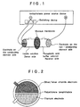
- This electrode structure is composed, for example, as shown in Fig. 2 ; however, it only exemplifies one embodiment and it goes without saying that it is not limited thereto. As shown in Fig.
- the electrode structure of the present invention is composed of a polarization electrode of titanium and alloys thereof, aluminum and alloys thereof, iron and alloys thereof and carbon and a non-polarization electrode of silver, copper, silver chloride, copper chloride, or materials based thereupon, for example, silver/silver chloride (silver with silver chloride adhered thereto or mixtures of both) and copper/copper chloride (copper with copper chloride adhered thereto or mixtures of both) with an electrical insulating material, for example, polyethylene terephthalate, polyethylene, polypropylene, polyvinylidene chloride, vinyl acetate copolymer, vinyl acetate/vinyl chloride copolymer, polyamide and cellophane provided between both.
- an electrical insulating material for example, polyethylene terephthalate, polyethylene, polypropylene, polyvinylidene chloride, vinyl acetate copolymer, vinyl acetate/vinyl chloride copolymer, polyamide and cellophan
- the polarization electrode and the non-polarization electrode are formed into a semicircular form respectively according to the circular sheet-like form in the example of Fig. 2 ; however, they are not limited to this embodiment but can be formed into a quadrangle, a pentagon or other proper forms with a proper thickness.
- the thickness and the size as a whole of the present electrode structure are selected properly according to the size and the form of diffusion cells in an iontophoresis device.
- both the polarization electrode and the non-polarization electrode are connected to the cathode side of a power source device in an iontophoresis device on the conducting element side, and can be switched freely according to the switching operation of the power source device.
- Fig. 1 shows an embodiment in the case of administering minus-charged biologically active substances or drugs.
- the switching device in the iontophoresis power source device is set on the anode side (plus pole side), and the electrode on the conducting element side is connected thereto.
- the electrode on the non-conducting element side is connected to the cathode side (minus pole side) in the iontophoresis power source device.
- the present invention has made it possible to transfer (namely, transport) biologically active substances or drugs into a living body in a sufficient amount and safely in administering biologically active substances or drugs through the skin or the mucous membrane.
- the electrode on the non-conducting element side namely the anode side in iontophoresis employing the electrode structure on the conducting element side of the present invention is employed a polarization electrode or a non-polarization electrode.
- materials for a polarization electrode are employed, for example, platinum, titanium, aluminum, iron, alloys thereof and carbon, and as materials for a non-polarization electrode are exemplified silver, copper and zinc.
- an electrode on the conducting element side and an electrode on the non-conducting element side can be mentioned one wherein the electrode on the conducting element side is an electrode structure comprising titanium and silver/silver chloride, and the electrode on the non-conducting element side is silver.
- the drugs are contained on the anode side and an electrode structure having both a polarization electrode and a non-polarization electrode on the anode side is employed.
- the polarization electrode in this case is employed titanium, aluminum, iron, platinum, an alloy thereof or carbon
- the non-polarization electrode is employed silver, copper or an alloy thereof.
- titanium and silver, and carbon and silver are employed.
- the drugs are contained on the cathode side and an electrode structure having both a polarization electrode and a non-polarization electrode on the cathode side is employed.
- the polarization electrode in this case is employed titanium, aluminum, iron, platinum, an alloy thereof or carbon
- the non-polarization electrode is employed an electrode based on silver chloride and copper chloride.
- titanium and silver/silver chloride, and carbon and silver/silver chloride are preferable combination.
- the biologically active substances or drugs employed and used in the practice of the present invention are not particularly limited and include, for example, anaesthetic agents, analgesic agents, anorexic agents, vermicides, antasthmatics, anticonvulsion agents, antidiarrheal agents, antimigraine agents, anti-motion-sickness agents, antivomiting agents, antitumor agents, anti-Parkinson s disease agents, antipruritics, antipyretic agents, synpathetic agents, xanthine derivatives, cardiovascular agents such as calcium transport route blocking agents, beta-blocking agents, antiarrhythmic agents, hypotensive agents, diuretic agents, vasodilators including the whole body, the coronal blood vessel, the peripheral blood vessel and the cerebral blood vessel, central nervous system excitatory state agents, drugs for coughs and colds, decogestants, diagonosis agents, hormones, sleeping drugs, immunosuppressants, muscle relaxants, parasympathetic suppressants, parasynpathetic agents
- biologically active substances or drugs include insulin of peptides, calcitonins, calcitonin-connected gene peptides, vasopressin, desmopressin, protirelin (TRH), adrenocorticotropic hormone (ACTH), luteinizing hormone-releasing factor (LH-RH), growth hormone-releasing factor (GRH), nerve growth factor (NGF) and other releasing factors, angiotensin, parathyroid hormone (PTH), thyroid-stimulating hormone (TSH, thyrotropin), follicle-stimulating hormone (FSH), luteinizing hormone (LH), prolactin, serumal gonadotropic hormone, placental gonadotropic hormone (HCG), pituitary gonadotropic hormone (HMG), growth hormone, somatostatin, somatomedin, glucagon, oxytocin, gastrins, secretin, endorphin, enkephalin, endoserine, cholestquinin, neuroten
- Fig. 1 is a schematic view showing an embodiment of an iontophoresis test device employing an iontophoresis electrode structure according to the present invention.
- Fig. 2 is a schematic view showing an embodiment of an iontophoresis electrode structure according to the present invention on the conducting element side.
- Fig. 3 is a diagram showing insulin concentration in blood after one hour in Examples of the present invention, and
- Fig. 4 is a diagram showing areas under the time curve of insulin concentration in blood in Examples of the present invention.
- Fig. 5 is a diagram showing the mucous membrane permeability of insulin till three hours after in Examples of the present invention, and
- Fig. 6 is a diagram showing an electrode time schedule in Example 2-3 in Test Example 2.
- Test Example 1 the back of a rat (a SD-strain rat: 250 g) was fixed, a diffusion cell was set thereon, and an insulin solution was administered thereto (amount of administration: 25 IU).
- a sodium chloride-containing PVA gel formed integrally together with an electrode was employed.
- an electrode on the conducting element side was connected to the cathode, and an electrode on the non-conducting element side was connected to the anode.
- the electrode on the conducting element side (cathode) in Examples was employed an electrode structure comprising a titanium electrode and a silver/silver chloride electrode with polyethylene terephthalate provided between both according to the constitution as shown in Fig. 2, and as the electrode on the non-conducting element side (anode) was employed a silver electrode.
- both the electrode on the conducting element side (cathode) and the electrode on the non-conducting element side (anode) in Comparative Examples were employed those to be described below.
- Example 1-1 Comparative Example 1-1, Comparative Example 1-2 and Comparative Example 1-3 were conducted.
- Example 1-1 electricity was turned on at a voltage of 12 V for 15 minutes after the start of the test, employing a titanium electrode (namely, a titanium electrode of an electrode structure comprising a titanium electrode and silver/silver chloride) on the conducting element side and a silver electrode on the non-conducting element side. Thereafter, electricity was turned on at a voltage of 6 V for 45 minutes, employing a silver/silver chloride electrode (namely, a silver/silver chloride electrode of an electrode structure comprising a titanium electrode and silver/silver chloride) on the conducting element side and the same silver electrode on the non-conducting element side.
- the insulin concentration in blood after one hour in total was about 1000 ⁇ IU/ml.
- the insulin concentration in blood - area under the time curve AUC ⁇ ⁇ 4h to the fourth hour was about 1.3 IU/ml min (see Fig. 3 and Fig. 4). No irritation was observed on the skin (see Table 1).
- a silver/silver chloride electrode was employed on the conducting element side and a silver electrode was employed on the non-conducting element side in Comparative Example 1-1 ; platinum electrodes were employed on both the conducting element side and the non-conducting element side in Comparative Example 1-2 ; and titanium electrodes were employed on both the conducting element side and the non-conducting element side in Comparative Example 1-3.
- Example 1-1 of the present invention it was possible to transfer insulin through the skin safely by employing the electrode structure comprising both a polarization electrode and a non-polarization electrode as in Example 1-1 of the present invention and employing the polarization electrode and the non-polarization electrode according to a switch with time.
- a non-polarization electrode or a polarization electrode singly as in Comparative Example 1-1, Comparative Example 1-2 and Comparative Example 1-3, it was difficult to transfer insulin into a living body without causing irritation on the skin.
- Test Example 2 the cheek bags of a hamster were extirpated, and the corneum of the cheek bags was removed by means of a cellophane tape, which was used as a model film of the transmucosa.
- the mucous membrane was set in a diffusion cell having two chambers for a permeability test as shown in Fig. 1 as the mucous membrane, and an electrode on the donor side and an electrode on the receiver side were connected to the iontophoresis power source device as a cathode and an anode respectively.
- the electrode on the conducting element side used in Examples was employed an electrode structure as shown in Fig. 2.
- the electrode structure is composed of a titanium electrode and a silver/silver chloride electrode with polyethylene terephthalate provided between both.
- the electrode on the conducting element side used in Comparative Examples was a single electrode without a switching device. After they were set as shown in Fig. 1, an insulin solution (insulin concentration: 60 IU) was supplied on the donor side, a phosphoric acid buffer solution was supplied on the receiver side, and Example 2-1, Example 2-2, Example 2-3, Comparative Example 2-1, Comparative Example 2-2 and Comparative Example 2-3 were conducted.
- Example 2-1 electricity was turned on at a voltage of 18 V for 15 minutes after the start of the test, employing the titanium electrode in the above electrode structure on the conducting element side and a silver electrode on the non-conducting side; thereafter, the switching device of the iontophoresis power source device was changed, and electricity was turned on at a voltage of 3 V for 2 hours 45 minutes, employing the silver/silver chloride electrode in the above electrode structure on the conducting element side and the same silver electrode on the non-conducting side.
- 0.7 IU of insulin per 1 cm 2 permeated the mucous membrane, and no irritation was observed on the mucous membrane.
- Example 2-2 electricity was turned on at a voltage of 18 V for 15 minutes after the start of the test, employing the titanium electrode in the above electrode structure on the conducting element side and a silver electrode on the non-conducting element side; thereafter, the switching device of the iontophoresis power source device was worked, and electricity was turned on at a voltage of 6 V for 2 hours 45 minutes, employing the silver chloride electrode in the above electrode structure on the conducting element side and the same silver electrode on the non-conducting side.
- 3 IU of insulin per 1 cm 2 permeated the mucous membrane in 3 hours in total, and no irritation was observed on the mucous membrane.
- Example 2-3 electricity was turned on at a voltage of 6 V for 5 minutes after the start of the test, employing the titanium electrode in the above electrode structure on the conducting element side and a silver electrode on the non-conducting element side; thereafter, the conducting element side was switched to the silver/silver chloride electrode in the above electrode structure, and electricity was turned on at a voltage of 6 V for 10 minutes (15 minutes in total). This was deemed as one cycle, and electricity was turned on over 12 cycles in total, namely, over 3 hours in total.
- Fig. 6 shows an electrode time schedule in Example 2-3. In the case of Example 2-3, 5 IU of insulin permeated the mucous membrane in 3 hours in total, and no irritation was observed on the mucous membrane (see Fig. 5 and Table 2).
- Comparative Example 2-3 electricity was turned on at a voltage of 18 V for 15 minutes after the start of the test and then at a voltage of 3 V for 2 hours and 45 minutes, employing titanium electrodes as electrodes on both the conducting element side and the non-conducting element side.
- Comparative Example 2-3 about 0.3 IU of insulin per 1 cm 2 permeated in 3 hours, but as a result of observing the mucous membrane after the completion of the test, irritation was observed thereon.
- Example 2 it was possible to transfer insulin through the mucous membrane without causing irritation through the mucous membrane by employing the electrode structure as employed in Example 2-1, Example 2-2 and Example 2-3.
- the electrode structure as employed in Example 2-1, Example 2-2 and Example 2-3.
- a non-polarization electrode or a polarization electrode singly as in Comparative Example 2-1, Comparative Example 2-2 and Comparative Example 2-3, it was not possible to allow insulin to permeate the mucous membrane without causing irritation on the mucous membrane.
- the present invention has made it possible to transfer biologically active substances and drugs into a living body through the skin and the mucous membrane, which was difficult according to prior arts, and to perform the transfer without causing irritation on the skin and the mucous membrane.
- Polarization electrodes comprising metals such as Ti, Al and Fe generally electrolyze water when electricity is turned on and generate OH - . Thereby the dissolution of the tissue of the skin and the mucous membrane slightly observed occurs. Substances can be transferred safely and efficiently further by performing iontophoresis administration, employing a non-polarization electrode.
- the back of a rat (a SD-strain rat: 250 g) was fixed, a diffusion cell was set thereon, an insulin solution was administered thereto (amount of administration: 25 IU), and the insulin solution side was made a compartment on the conducting element side.
- a sodium chloride-containing PVA gel formed integrally together with an electrode.
- An electrode on the conducting element side was connected to the cathode of the iontophoresis power source device, and an electrode on the non-conducting element side was connected to the iontophoresis power source device as the anode. After electricity started to be turned on, blood was collected from the rat with time, and insulin concentration in the collected blood was measured.
- Electricity was turned on at a voltage of 12 V for 15 minutes after the start of the test, employing a titanium electrode as the electrode on the conducting element side and a silver electrode as the electrode on the non-conducting element side; thereafter, electricity was turned on at a voltage of 6 V for 45 minutes, employing a silver/silver chloride electrode as the electrode on the conducting element side and a silver electrode as the electrode on the non-conducting element side.
- Electricity was turned on at a voltage of 12 V for 15 minutes after the start of the test, employing a silver/silver chloride electrode on the conducting element side and a silver electrode on the non-conducting element side; thereafter, electricity was turned on at a voltage of 3 V for 45 minutes.
- Electricity was turned on at a voltage of 12 V for 15 minutes after the start of the test, employing platinum electrodes as electrodes on both the conducting element side and the non-conducting element side; thereafter, electricity was turned on at a voltage of 3 V for 45 minutes.
- Electricity was turned on at a voltage of 12 V for 15 minutes after the start of the test, employing titanium electrodes as electrodes on both the conducting element side and the non-conducting element side; thereafter, electricity was turned on at a voltage of 3 V for 45 minutes.
- a two-chamber diffusion cell device for a permeability test as shown in Fig. 1 was employed, and the electrode on the conducting element side in Examples was employed an electrode structure as shown in Fig. 2.
- the electrode on the conducting element side (cathode) and the electrode on the non-conducting element side (anode) in Comparative Examples were employed electrodes to be described below.
- the cheek bags of a hamster (a syrian golden hamster; weight: 100 to 150 g) were extirpated, and the corneum thereof was removed by means of a cellophane tape.
- the film was set in the two-chamber diffusion cell for a permeability test.
- An insulin solution (insulin concentration: 60 IU) was applied onto the compartment on the donor side (conducting element side), and a phosphoric acid buffer solution was applied onto the compartment on the receiver side (non-conducting element side).
- the electrode on the donor side and the electrode on the receiver side were connected to the iontophoresis power source device as a cathode and an anode respectively. Besides, after the completion of the test, the mucous membrane was observed.
- Example 2-1 to Example 2-3 The electrodes with electricity turned on and the time while electricity was turned on are as described in Example 2-1 to Example 2-3 and Comparative Example 2-1 to Comparative Example 2-3 below respectively. The results thereof are as shown in Fig. 5 and Table 2. Mucous membrane irritation Presence of irritation Example 2-1 Nil Example 2-2 Nil Example 2-3 Nil Comparative Example 2-1 Nil Comparative Example 2-2 Nil Comparative Example 2-3 Observed
- Electricity was turned on at a voltage of 18 V for 15 minutes after the start of the test, employing a titanium electrode as the electrode on the conducting element side and a silver electrode as the electrode on the non-conducting element side; thereafter, electricity was turned on at a voltage of 3 V for 2 hours 45 minutes, employing a silver/silver chloride electrode as the electrode on the conducting element side and a silver electrode as the electrode on the non-conducting element side.
- Electricity was turned on at a voltage of 18 V for 15 minutes after the start of the test, employing a titanium electrode as the electrode on the conducting element side and a silver electrode as the electrode on the non-conducting element side; thereafter, electricity was turned on at a voltage of 6 V for 2 hours 45 minutes, employing a silver/silver chloride electrode as the electrode on the conducting element side and a silver electrode as the electrode on the non-conducting element side.
- Electricity was turned on at a voltage of 6 V for 5 minutes after the start of the test, employing a titanium electrode as the electrode on the conducting element side and a silver electrode as the electrode on the non-conducting element side; thereafter, electricity was turned on at a voltage of 6 V for 10 minutes, employing a silver/silver chloride electrode as the electrode on the conducting element side (15 minutes in total). This was deemed as one cycle, and electricity was turned on over 12 cycles in total, namely, over 3 hours.
- Fig. 6 shows an electrode time schedule in Exampe 2-3.
- Electricity was turned on at a voltage of 18 V for 15 minutes after the start of the test, employing a silver/silver chloride electrode on the conducting element side and a silver electrode on the non-conducting element side; thereafter, electricity was turned on at a voltage of 3 V for 2 hours 45 minutes.
- Electricity was turned on at a voltage of 18 V for 15 minutes after the start of the test, employing platinum electrodes as electrodes on both the conducting element side and the non-conducting element side; thereafter, electricity was turned on at a voltage of 3 V for 2 hours 45 minutes.
- Electricity was turned on at a voltage of 18 V for 15 minutes after the start of the test, employing titanium electrodes as electrodes on both the conducting element side and the non-conducting element side; thereafter, electricity was turned on at a voltage of 3 V for 2 hours 45 minutes.
- the present invention makes it possible in iontophoresis to transfer biologically active substances and drugs into a living body in administration through the skin and the mucous membrane in a sufficient amount and safely by employing an electrode structure having both a polarization electrode and a non-polarization electrode as electrodes on the conducting element side and using the polarization electrode or the non-polarization electrode according to a proper switch, and can transfer biologically active substances and drugs through the skin and the mucous membrane effectively without causing irritation.
Landscapes
- Health & Medical Sciences (AREA)
- Engineering & Computer Science (AREA)
- Biomedical Technology (AREA)
- Nuclear Medicine, Radiotherapy & Molecular Imaging (AREA)
- Radiology & Medical Imaging (AREA)
- Life Sciences & Earth Sciences (AREA)
- Animal Behavior & Ethology (AREA)
- General Health & Medical Sciences (AREA)
- Public Health (AREA)
- Veterinary Medicine (AREA)
- Bioinformatics & Cheminformatics (AREA)
- Electrotherapy Devices (AREA)
- Treatments Of Macromolecular Shaped Articles (AREA)
Applications Claiming Priority (1)
| Application Number | Priority Date | Filing Date | Title |
|---|---|---|---|
| PCT/JP1995/001619 WO1997006848A1 (en) | 1995-08-14 | 1995-08-14 | Electrode structure for iontophoresis |
Publications (3)
| Publication Number | Publication Date |
|---|---|
| EP0845280A1 true EP0845280A1 (de) | 1998-06-03 |
| EP0845280A4 EP0845280A4 (de) | 2000-08-16 |
| EP0845280B1 EP0845280B1 (de) | 2003-10-22 |
Family
ID=14126188
Family Applications (1)
| Application Number | Title | Priority Date | Filing Date |
|---|---|---|---|
| EP95928028A Expired - Lifetime EP0845280B1 (de) | 1995-08-14 | 1995-08-14 | Elektrode für iontophorese |
Country Status (9)
| Country | Link |
|---|---|
| US (1) | US6104951A (de) |
| EP (1) | EP0845280B1 (de) |
| JP (1) | JP3565903B2 (de) |
| KR (1) | KR100357911B1 (de) |
| AT (1) | ATE252406T1 (de) |
| AU (1) | AU703986B2 (de) |
| CA (1) | CA2229604C (de) |
| DE (1) | DE69532002T2 (de) |
| WO (1) | WO1997006848A1 (de) |
Families Citing this family (6)
| Publication number | Priority date | Publication date | Assignee | Title |
|---|---|---|---|---|
| EP1484084A4 (de) * | 2002-01-24 | 2009-12-23 | Hisamitsu Pharmaceutical Co | Elektrodenstruktur |
| US8197844B2 (en) | 2007-06-08 | 2012-06-12 | Activatek, Inc. | Active electrode for transdermal medicament administration |
| EP2020249A1 (de) | 2007-08-01 | 2009-02-04 | Boehringer Ingelheim Pharma GmbH & Co. KG | Inhalator |
| US8862223B2 (en) | 2008-01-18 | 2014-10-14 | Activatek, Inc. | Active transdermal medicament patch and circuit board for same |
| KR20130037903A (ko) * | 2011-10-07 | 2013-04-17 | (주)휴비딕 | 양극형 프로브 헤드가 구비된 이온 도입기 |
| CZ2013852A3 (cs) * | 2013-11-06 | 2015-10-29 | Mojmír Čermák | Elektronické germicidní zařízení |
Family Cites Families (16)
| Publication number | Priority date | Publication date | Assignee | Title |
|---|---|---|---|---|
| US3606881A (en) * | 1970-02-20 | 1971-09-21 | Riley D Woodson | Conductive rubber electrode |
| US4406658A (en) * | 1981-03-06 | 1983-09-27 | Medtronic, Inc. | Iontophoretic device with reversible polarity |
| US4820263A (en) * | 1981-03-06 | 1989-04-11 | Medtronic, Inc. | Apparatus and method for iontophoretic drug delivery |
| CA1262564A (en) * | 1983-09-01 | 1989-10-31 | Minoru Sasaki | Iontophoresis device |
| US5006108A (en) * | 1988-11-16 | 1991-04-09 | Noven Pharmaceuticals, Inc. | Apparatus for iontophoretic drug delivery |
| US5088978A (en) * | 1990-01-26 | 1992-02-18 | Gensia Pharmaceuticals, Inc. | Apparatus and method for iontophoretic transfer |
| US5224927A (en) * | 1990-11-01 | 1993-07-06 | Robert Tapper | Iontophoretic treatment system |
| JP3488466B2 (ja) * | 1992-06-02 | 2004-01-19 | アルザ・コーポレーション | 電気駆動式薬物投与デバイス |
| JPH0772999A (ja) * | 1992-10-20 | 1995-03-17 | Hewlett Packard Co <Hp> | 画面対応ソフトウェアアプリケーションツールにおける表示画面事象をモニターする方法と装置 |
| JPH06327777A (ja) * | 1993-03-26 | 1994-11-29 | Gijutsu Kenkyu Kumiai Iryo Fukushi Kiki Kenkyusho | 電気的薬剤導入装置 |
| WO1994028967A1 (en) * | 1993-06-08 | 1994-12-22 | Hisamitsu Pharmaceutical Co., Inc. | Iontophoresis system |
| CA2126487C (en) * | 1993-06-23 | 2001-05-29 | Keiichiro Okabe | Iontophoresis device |
| WO1995009032A1 (en) * | 1993-09-30 | 1995-04-06 | Becton, Dickinson And Company | Iontophoretic drug delivery system and method |
| US5445856A (en) * | 1993-11-10 | 1995-08-29 | Chaloner-Gill; Benjamin | Protective multilayer laminate for covering an electrochemical device |
| US5871460A (en) * | 1994-04-08 | 1999-02-16 | Alza Corporation | Electrotransport system with ion exchange material providing enhanced drug delivery |
| US5540654A (en) * | 1994-09-02 | 1996-07-30 | North Carolina State University | Iontophoretic electrode |
-
1994
- 1994-06-25 JP JP16597994A patent/JP3565903B2/ja not_active Expired - Fee Related
-
1995
- 1995-08-14 AU AU31934/95A patent/AU703986B2/en not_active Ceased
- 1995-08-14 US US09/029,316 patent/US6104951A/en not_active Expired - Lifetime
- 1995-08-14 DE DE69532002T patent/DE69532002T2/de not_active Expired - Fee Related
- 1995-08-14 CA CA002229604A patent/CA2229604C/en not_active Expired - Fee Related
- 1995-08-14 KR KR10-1998-0700998A patent/KR100357911B1/ko not_active Expired - Fee Related
- 1995-08-14 AT AT95928028T patent/ATE252406T1/de not_active IP Right Cessation
- 1995-08-14 WO PCT/JP1995/001619 patent/WO1997006848A1/ja not_active Ceased
- 1995-08-14 EP EP95928028A patent/EP0845280B1/de not_active Expired - Lifetime
Also Published As
| Publication number | Publication date |
|---|---|
| ATE252406T1 (de) | 2003-11-15 |
| DE69532002T2 (de) | 2004-05-19 |
| AU3193495A (en) | 1997-03-12 |
| CA2229604A1 (en) | 1997-02-27 |
| JP3565903B2 (ja) | 2004-09-15 |
| EP0845280B1 (de) | 2003-10-22 |
| CA2229604C (en) | 2002-04-09 |
| KR100357911B1 (ko) | 2003-01-29 |
| JPH08743A (ja) | 1996-01-09 |
| EP0845280A4 (de) | 2000-08-16 |
| KR19990036330A (ko) | 1999-05-25 |
| US6104951A (en) | 2000-08-15 |
| WO1997006848A1 (en) | 1997-02-27 |
| DE69532002D1 (de) | 2003-11-27 |
| AU703986B2 (en) | 1999-04-01 |
Similar Documents
| Publication | Publication Date | Title |
|---|---|---|
| EP0705619B1 (de) | Iontophoresegerät | |
| US6978172B2 (en) | Method for in vivo delivery of therapeutic agents | |
| EP0429842B1 (de) | Vorrichtung zur transdermalen Applikation von Protein- oder Peptid-Medikamenten | |
| US6654635B1 (en) | Iontophoresis device | |
| EP0774272B1 (de) | Elektrode für iontophorese und vorrichtung dafür | |
| US6141582A (en) | Iontophoresis system and its control process of current | |
| JPH06506616A (ja) | イオン電気導入薬剤投与中の刺激を軽減させるためのデバイス | |
| US5766144A (en) | High efficiency electrode system for iontophoresis | |
| US6104951A (en) | Iontophoresis electrode structure | |
| AU754571B2 (en) | Iontophoresis device and method of assembling the same | |
| JP3247931B2 (ja) | イオントフォレーシス電極デバイス | |
| JPH0616538A (ja) | イオントフォレーゼのための薬物吸収用液組成物 | |
| JP3414906B2 (ja) | イオントフォレーシス電極 | |
| KR930000062B1 (ko) | 단백 및 펩타이드성 약물의 경피투여조성물 | |
| JPH09187520A (ja) | 経皮又は経粘膜薬物送達方法 |
Legal Events
| Date | Code | Title | Description |
|---|---|---|---|
| PUAI | Public reference made under article 153(3) epc to a published international application that has entered the european phase |
Free format text: ORIGINAL CODE: 0009012 |
|
| 17P | Request for examination filed |
Effective date: 19980209 |
|
| AK | Designated contracting states |
Kind code of ref document: A1 Designated state(s): AT BE CH DE DK ES FR GB GR IE IT LI NL PT SE |
|
| A4 | Supplementary search report drawn up and despatched |
Effective date: 20000703 |
|
| AK | Designated contracting states |
Kind code of ref document: A4 Designated state(s): AT BE CH DE DK ES FR GB GR IE IT LI NL PT SE |
|
| 17Q | First examination report despatched |
Effective date: 20010727 |
|
| GRAH | Despatch of communication of intention to grant a patent |
Free format text: ORIGINAL CODE: EPIDOS IGRA |
|
| GRAH | Despatch of communication of intention to grant a patent |
Free format text: ORIGINAL CODE: EPIDOS IGRA |
|
| GRAA | (expected) grant |
Free format text: ORIGINAL CODE: 0009210 |
|
| AK | Designated contracting states |
Kind code of ref document: B1 Designated state(s): AT BE CH DE DK ES FR GB GR IE IT LI NL PT SE |
|
| PG25 | Lapsed in a contracting state [announced via postgrant information from national office to epo] |
Ref country code: LI Free format text: LAPSE BECAUSE OF FAILURE TO SUBMIT A TRANSLATION OF THE DESCRIPTION OR TO PAY THE FEE WITHIN THE PRESCRIBED TIME-LIMIT Effective date: 20031022 Ref country code: CH Free format text: LAPSE BECAUSE OF FAILURE TO SUBMIT A TRANSLATION OF THE DESCRIPTION OR TO PAY THE FEE WITHIN THE PRESCRIBED TIME-LIMIT Effective date: 20031022 Ref country code: BE Free format text: LAPSE BECAUSE OF FAILURE TO SUBMIT A TRANSLATION OF THE DESCRIPTION OR TO PAY THE FEE WITHIN THE PRESCRIBED TIME-LIMIT Effective date: 20031022 Ref country code: AT Free format text: LAPSE BECAUSE OF FAILURE TO SUBMIT A TRANSLATION OF THE DESCRIPTION OR TO PAY THE FEE WITHIN THE PRESCRIBED TIME-LIMIT Effective date: 20031022 |
|
| REG | Reference to a national code |
Ref country code: GB Ref legal event code: FG4D |
|
| REG | Reference to a national code |
Ref country code: CH Ref legal event code: EP |
|
| REG | Reference to a national code |
Ref country code: IE Ref legal event code: FG4D |
|
| REF | Corresponds to: |
Ref document number: 69532002 Country of ref document: DE Date of ref document: 20031127 Kind code of ref document: P |
|
| PG25 | Lapsed in a contracting state [announced via postgrant information from national office to epo] |
Ref country code: SE Free format text: LAPSE BECAUSE OF FAILURE TO SUBMIT A TRANSLATION OF THE DESCRIPTION OR TO PAY THE FEE WITHIN THE PRESCRIBED TIME-LIMIT Effective date: 20040122 Ref country code: GR Free format text: LAPSE BECAUSE OF FAILURE TO SUBMIT A TRANSLATION OF THE DESCRIPTION OR TO PAY THE FEE WITHIN THE PRESCRIBED TIME-LIMIT Effective date: 20040122 Ref country code: DK Free format text: LAPSE BECAUSE OF FAILURE TO SUBMIT A TRANSLATION OF THE DESCRIPTION OR TO PAY THE FEE WITHIN THE PRESCRIBED TIME-LIMIT Effective date: 20040122 |
|
| PG25 | Lapsed in a contracting state [announced via postgrant information from national office to epo] |
Ref country code: ES Free format text: LAPSE BECAUSE OF FAILURE TO SUBMIT A TRANSLATION OF THE DESCRIPTION OR TO PAY THE FEE WITHIN THE PRESCRIBED TIME-LIMIT Effective date: 20040202 |
|
| REG | Reference to a national code |
Ref country code: CH Ref legal event code: PL |
|
| ET | Fr: translation filed | ||
| PG25 | Lapsed in a contracting state [announced via postgrant information from national office to epo] |
Ref country code: GB Free format text: LAPSE BECAUSE OF NON-PAYMENT OF DUE FEES Effective date: 20040814 |
|
| PG25 | Lapsed in a contracting state [announced via postgrant information from national office to epo] |
Ref country code: IE Free format text: LAPSE BECAUSE OF NON-PAYMENT OF DUE FEES Effective date: 20040816 |
|
| PLBE | No opposition filed within time limit |
Free format text: ORIGINAL CODE: 0009261 |
|
| STAA | Information on the status of an ep patent application or granted ep patent |
Free format text: STATUS: NO OPPOSITION FILED WITHIN TIME LIMIT |
|
| 26N | No opposition filed |
Effective date: 20040723 |
|
| PG25 | Lapsed in a contracting state [announced via postgrant information from national office to epo] |
Ref country code: NL Free format text: LAPSE BECAUSE OF NON-PAYMENT OF DUE FEES Effective date: 20050301 Ref country code: DE Free format text: LAPSE BECAUSE OF NON-PAYMENT OF DUE FEES Effective date: 20050301 |
|
| GBPC | Gb: european patent ceased through non-payment of renewal fee |
Effective date: 20040814 |
|
| PG25 | Lapsed in a contracting state [announced via postgrant information from national office to epo] |
Ref country code: FR Free format text: LAPSE BECAUSE OF NON-PAYMENT OF DUE FEES Effective date: 20050429 |
|
| NLV4 | Nl: lapsed or anulled due to non-payment of the annual fee |
Effective date: 20050301 |
|
| REG | Reference to a national code |
Ref country code: IE Ref legal event code: MM4A |
|
| REG | Reference to a national code |
Ref country code: FR Ref legal event code: ST |
|
| PG25 | Lapsed in a contracting state [announced via postgrant information from national office to epo] |
Ref country code: IT Free format text: LAPSE BECAUSE OF NON-PAYMENT OF DUE FEES Effective date: 20050814 |
|
| PG25 | Lapsed in a contracting state [announced via postgrant information from national office to epo] |
Ref country code: PT Free format text: LAPSE BECAUSE OF NON-PAYMENT OF DUE FEES Effective date: 20040322 |