EP0846541A2 - Vorrichtung zur Herstellung eines kontinuierlichen Schaumformkörpers mit verstellbarer Wand - Google Patents
Vorrichtung zur Herstellung eines kontinuierlichen Schaumformkörpers mit verstellbarer Wand Download PDFInfo
- Publication number
- EP0846541A2 EP0846541A2 EP97203668A EP97203668A EP0846541A2 EP 0846541 A2 EP0846541 A2 EP 0846541A2 EP 97203668 A EP97203668 A EP 97203668A EP 97203668 A EP97203668 A EP 97203668A EP 0846541 A2 EP0846541 A2 EP 0846541A2
- Authority
- EP
- European Patent Office
- Prior art keywords
- mold
- cover
- segments
- side walls
- molding
- Prior art date
- Legal status (The legal status is an assumption and is not a legal conclusion. Google has not performed a legal analysis and makes no representation as to the accuracy of the status listed.)
- Granted
Links
Images


Classifications
-
- B—PERFORMING OPERATIONS; TRANSPORTING
- B29—WORKING OF PLASTICS; WORKING OF SUBSTANCES IN A PLASTIC STATE IN GENERAL
- B29C—SHAPING OR JOINING OF PLASTICS; SHAPING OF MATERIAL IN A PLASTIC STATE, NOT OTHERWISE PROVIDED FOR; AFTER-TREATMENT OF THE SHAPED PRODUCTS, e.g. REPAIRING
- B29C44/00—Shaping by internal pressure generated in the material, e.g. swelling or foaming ; Producing porous or cellular expanded plastics articles
- B29C44/20—Shaping by internal pressure generated in the material, e.g. swelling or foaming ; Producing porous or cellular expanded plastics articles for articles of indefinite length
- B29C44/26—Shaping by internal pressure generated in the material, e.g. swelling or foaming ; Producing porous or cellular expanded plastics articles for articles of indefinite length using several expanding steps
-
- B—PERFORMING OPERATIONS; TRANSPORTING
- B29—WORKING OF PLASTICS; WORKING OF SUBSTANCES IN A PLASTIC STATE IN GENERAL
- B29C—SHAPING OR JOINING OF PLASTICS; SHAPING OF MATERIAL IN A PLASTIC STATE, NOT OTHERWISE PROVIDED FOR; AFTER-TREATMENT OF THE SHAPED PRODUCTS, e.g. REPAIRING
- B29C44/00—Shaping by internal pressure generated in the material, e.g. swelling or foaming ; Producing porous or cellular expanded plastics articles
- B29C44/34—Auxiliary operations
- B29C44/58—Moulds
- B29C44/585—Moulds with adjustable size of the mould cavity
Definitions
- the present invention relates to an apparatus for molding a continuous element of foamed plastics.
- the present invention relates, more particularly, to an apparatus for molding a continuous element of foamed plastics which finds a preferred, although not exclusive use, as a construction member in the building industry.
- continuous foamed plastic element is used to indicate a foamed plastic section bar, e.g. made of foamed polystyrene, which leaves the molding apparatus as a single piece substantially free from joints or breaks and having indefinite length.
- foamed plastic construction elements preferably made of foamed polystyrene, in the form of sheets or section bars of appropriate shape and size, having the function of thermal and acoustic insulating material.
- the construction elements of the type considered are obtained by cutting in pieces of predetermined length a continuous element produced by means of molding apparatuses comprising a mold in which a molding seat is defined having a shape mating that of the continuous element to be produced.
- a metered quantity of expandable plastic material in granules is fed into the above mentioned seat and subjected to expansion with a mutual welding of the granules through the action of heat, so as to form a new portion of the continuous element and obtain its simultaneous welding with an adjacent portion formed in a preceding molding cycle.
- the mold is opened and the continuous element incorporating the new portion is made to advance by a distance corresponding to the length of the molding seat, so as to arrange the latter for receiving other granules and initiating a new production cycle.
- the molding apparatus of the prior art displays poor operating flexibility and, more specifically, does not allow an easy control of the shape, and in particular of the height, of the continuous foamed plastic element where required.
- the prior art proposes to change the height of the molding seat defined in the mold, by inserting spacers of adequate thickness into the cover each time as needed.
- the technical problem underlying the present invention is therefore that of providing an apparatus for molding a continuous foamed plastic element capable of overcoming the above-mentioned drawbacks of the prior art.
- an apparatus for molding a continuous foamed plastic element comprising a mold including:
- the mold cover comprises a pair of segments longitudinally spanning along the full length of the forming chamber and, respectively, of the stabilization chamber.
- each of said forming and stabilization chambers of the foamed plastics element may be independently adjusted in a substantially continuous manner between minimum and maximum values which are preset at the design stage, by means of at least one power driven jack arranged to act on each of the independent cover segments.
- each of the independent cover segments comprises a plurality of jacks kinematically connected together by means of a shaft which is rotated by suitable motor means.
- the apparatus of the invention further comprises means for clamping together the independent cover segments, so as to provide an adequate fluid-tight closure during the molding operations.
- such means comprises a plurality of Belleville washers mounted on one of the independent segments of the cover and acting thereon to hold the same pressed against the adjacent segment.
- the apparatus of the invention preferably comprises a sealing plate interposed between the independent segments that make up the cover.
- this sealing plate is attached to an end wall of one of the segments such as, but not necessarily, the segment carrying the Belleville washers.
- the sealing plate outer surface is lined with a suitable self-lubricating material for smoother sliding movements of the cover segments along the vertical direction, and to preserve the surface integrity of the side walls of the segments constantly held in mutual contact.
- an apparatus for molding a continuous foamed plastics element of the type comprising a substantially parallelepipedic central body and at least one projection laterally and longitudinally extending from said body, said apparatus including a mold comprising:
- At least one, better still both, of the side walls of the mold comprise a pair of segments longitudinally extending along the length of the forming chamber and, respectively, of the stabilization chamber of the mold.
- each molding seat wherein the lateral projection of the foamed plastics element is formed is preferably adjusted in an independent and substantially continuous manner between minimum and maximum values which are preset at the design stage, by means of at least one power driven jack acting on each of the independent segments of the side wall.
- each of the independent segments of the side wall -- defining together with the bottom wall of the mold the second molding seat of the lateral projection -- is provided with a plurality of jacks kinematically connected by means of a shaft which is rotated by suitable motor means.
- the apparatus of the present invention further comprises means for clamping together the independent segments of the side wall, so as to provide an adequate fluid-tight closure during the molding operations.
- such means comprises a plurality of Belleville washers mounted on one of the independent segments of the side wall and acting on that segment to hold it pressed against the adjacent segment.
- the apparatus of the invention preferably comprises a sealing plate interposed between said independent segments of the side wall.
- this sealing plate is fixed to an end wall of one of the segments such as, but not necessarily, the segment carrying the Belleville washers.
- the sealing plate is lined on its outer surface with a suitable self-lubricating material for smoother sliding movements of the side wall segments along the vertical direction, as well as to preserve the surface integrity of the side walls of the segments constantly held in mutual contact.
- an apparatus for continuously molding a foamed plastics element as previously indicated said apparatus including a mold comprising:
- the height of the first molding seat of the foamed plastics element -- or at least its overall height -- may in this case be adjusted simultaneously and independently of the height of the molding seat defining its lateral projections, both in the forming chamber and in the stabilization chamber of the mold.
- an apparatus according to the invention for molding a continuous foamed plastics element, such as a continuous element 2 for use in the construction of building floors.
- the element 2 comprises a body 3, wherein a plurality of longitudinal parallel cavities 4 are defined, and a pair of projections 5, 6 laterally and longitudinally extending along opposite sides of the body 3.
- the continuous element 2 incorporates two reinforcing sectional members 7, 8, structurally identical with one another, embedded in mirror-image relationship with respect to a longitudinal plane of symmetry of the element and longitudinally extending in the central body 3 along substantially the full length of the continuous element 2.
- the reinforcing sectional members 7, 8 are formed by suitably shaping a cold-rolled zinc-galvanized metal sheet by means of apparatuses known per se.
- the reinforcing sectional members 7, 8, are substantially Z-shaped and comprise a central portion 9 and a pair of respectively lower and upper fins 11, 12 perpendicularly extending along opposite directions from the ends of the central portion 10.
- the continuous element 2 further comprises a wire lath 12, for supporting at least one layer of a suitable covering material, such as plaster, welded to the lower fins 10 of the reinforcing sectional members 7, 8.
- a suitable covering material such as plaster
- the fins 10 lie substantially flush with and substantially parallel to the lower face of the continuous element 2.
- the lath 12 is suitably folded at its opposite side ends to form a first oblique lath section fully embedded in the projections 5, 6, and a second lath section extending in a substantially vertical direction partly flush with the opposite lateral sides of the continuous element 2.
- the apparatus 1 includes a mold 13 mounted on a supporting structure which comprises a pair of parallel beams 14a, 14b spaced apart from each other and stiffened by a plurality of beams 15 ( Figures 3 and 4).
- the beams 14a, 14b support a substantially cage-like structure, generally denoted by 16, which comprises two pairs of uprights 17a-17b and 17c-17d parallel to each other and symmetrically extending on opposite sides of the apparatus 1.
- each of said pairs 17a-17b and 17c-17d are reciprocally spaced apart and stiffened by respective pairs of crosspieces 18a-18b and longitudinal beams 18c-18d extending transversely and, respectively, parallel to the mold 13 ( Figure 5).
- the mold 13 of the molding apparatus 1 essentially comprises a pair of opposite parallel side walls 20, 21, a bottom wall 22, and a cover 23 defining -- in cooperation with a vertical closure plate 24 supported at a rear end of the mold 13 -- a substantially tunnel-shaped molding seat having a shape mating that of the element 2.
- the mold 13, furthermore, is divided, as more clearly explained hereinafter, into a rear chamber 13a intended for forming a segment of predetermined length of the element 2 by expanding the plastic material in granules, and a front chamber 13b adjacent to the rear chamber and designed to allow a shape stabilization of the segment formed during a previous molding cycle.
- front and rear are used to indicate those parts and accessories of the apparatus 1 which are located at the open portion of the mold 13 adapted to withdraw the element and, respectively, at the closed portion of the mold wherein the plastics granules are loaded for molding.
- the closure plate 24 posteriorly closes the forming seat defined in the chamber 13a of the mold 13, and is preferably lined with a grooved self-lubricating sheet, e.g. of polytetrafluoroethylene, adapted to form a corresponding grooved surface of mating shape on one end of the element 2.
- a grooved self-lubricating sheet e.g. of polytetrafluoroethylene
- This grooved surface allows to optimize the reciprocal welding between adjacent segments of the element 2 as they are molded by the apparatus 1 during successive molding cycles.
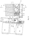
- the bottom wall 22 of the mold 13 is supported by a base 25, also having an essentially cage-like structure, which bears on a plurality of beams 26 extending crosswise to the mold 13 and supported in turn by a plurality of box-like supporting members 85 ( Figures 1 and 2).
- Each beam 26 also pivotally supports, on opposite sides thereof, two double-acting hydraulic cylinders, denoted by 27 and 28, which are parts of oppositely located devices 29a, 29b for laterally opening the side walls 20 and, respectively, 21 which will be described in more detail hereinbelow.
- the side walls 20 and 21, the bottom wall 22, and the cover 23 of the mold 13 essentially consist of a pair of segments longitudinally extending along the length of the forming chamber 13a and, respectively, of the stabilization chamber 13b of the mold 13.
- Each of said independent segments essentially consists of a hollow box-type body, wherein a chamber is defined which is fed, in suitable sequential order, by appropriate fluids (usually steam, cooling water and compressed air) for heating and cooling the segment of the element 2 being molded.
- appropriate fluids usually steam, cooling water and compressed air
- these chambers will be indicated by the references 36a, 36b for the segments 20a and 20b of the side wall 20; 37a, 37b for the segments 21a and 21b of the side wall 21; 38a, 38b for the segments 22a and 22b of the bottom wall 22; and 39a, 39b for the segments 23a and 23b of the cover 23.
- each of said segments is provided with a plurality of slits, collectively denoted by 41 ( Figures 9 and 10).
- Each of the segments 20a-20b and 21a-21b of the side walls 20 and 21 of the mold 13 is provided in the embodiment shown with a substantially L-shaped groove which longitudinally spans along the full length thereof.
- These grooves have predetermined height and depth, defined at the design stage as a function of the particular shape to be conferred to the lateral projections 5, 6 of the element 2.
- the second molding seats 45, 46 are defined between the L-shaped grooves formed in each segment of the side walls 20, 21 and the bottom wall 22 of the mold 13.
- the apparatus 1 of the example shown is provided with suitable means for displacing the cover 23 toward and away from the bottom wall 22, to longitudinally close and, respectively, open the mold 13.
- said means comprises a pair of actuators 47, 48 adapted to displace the rear segment 23a and, respectively, the front segment 23b of the cover 23.
- the actuators 47, 48 comprise three jacks, respectively denoted by references 49 and 50, pitchwise spaced from one another so as to allow an adequate parallelism of upward/downward motion of the cover 23.
- each of the jacks 49 and 50 is supported by a supporting beam 40, extending crosswise to the mold 13, the opposite ends of which are fixed to a pair of longitudinal girders 86a, 86b.
- the latter are conventionally fixed to the front and rear crosspieces 18a, 18b of the cage-like structure 16 and extend parallel to the longitudinal beams 18c and 18d.
- the parallelism of upward/downward motion of the cover 23 is also ensured by a plurality of cylindrical rods 51, attached to the cover segments 23a, 23b, which are slidably engaged in respective bushes 52 fixed to corresponding beams 87 extending crosswise to the mold 13 and parallel to the beams 40 supporting the jacks 49 and 50.
- the actuators 47, 48 and the cylindrical rods 51 form together means for mounting and connecting the cover 23 to the cage-like structure 16.
- the jacks 49 of the actuator 47 are driven by an electric motor 53 through a reduction gear and a conventional drive, known per se, including a shaft 54 and a gear train, not shown.
- the jacks 50 of the actuator 48 are driven by an electric motor 55 through a reduction gear and a conventional drive, also known per se, including a shaft 56 and a gear train, not shown.
- the actuators 47, 48 constitute respective means for positioning in an adjustable manner each of the independent segments 23a, 23b of the cover 23, toward and away from the bottom wall 22 of the mold 13, so as to regulate in an independent and substantially continuous manner the height of each of the forming and stabilization chambers 13a, 13b of the mold.
- the segments 23a and 23b of the cover 23 may be independently and adjustably positioned by means of the actuators 47 and 48, toward and away from the bottom wall 22, to independently regulate in a substantially continuous manner the height of the molding seat 44 of the central body 3 of the element 2.
- the height of the central body 3 of the continuous element 2 may be varied between 50 and 320 mm; the maximum range of adjustment is instead of about 160 mm.
- the apparatus 1 further comprises means for clamping together the independent segments 23a, 23b of the cover 23 so as to provide, during the molding operations, an adequately fluid-tight seal of the cover 23 against leakage of the process fluids (steam, cooling water and compressed air) employed.
- process fluids steam, cooling water and compressed air
- such means comprises a plurality of Belleville washers 57, known per se, which are supported by the rear segment 23a of the cover 23 above the chamber 39a ( Figures 7 and 8).
- the Belleville washers 57 exert a constant and uniform pressure against the segment 23b, thereby ensuring the structural and functional continuity of the cover 23.
- a sealing plate 58 fixed to an end wall of the segment 23a, provides an adequate fluid-tight seal between the adjacent segments of the cover 23.
- the outer surface of the sealing plate 58 is lined with a suitable self-lubricating material, such as polytetrafluoroethylene, so as to facilitate the sliding movements of the segments 23a and 23b relative to each other along the vertical direction and to preserve the surface integrity of the segment side walls held in constant mutual contact.
- a suitable self-lubricating material such as polytetrafluoroethylene
- each of the side walls 20, 21 of the mold 13 is respectively slidably supported by a pair of parallel girders 30-31 and 32-33 longitudinally extending along the whole length of the mold (figures 3 and 4).
- each of the segments 20a,b and 21a,b of the side walls is independently slidably supported by the girders 30-31 and 32-33 by means of respective positioning devices, indicated by references 34a,b and 35a,b which will be described in greater detail hereinafter.
- the girders 30 and 31, supporting and stiffening the side wall 20, are conventionally fixed to three substantially L-shaped arms 59 which are pitchwise spaced from one another and supported by the beams 40, onto which they are pivotally connected by means of respective hinges having horizontal axis collectively denoted by 61 ( Figures 3 and 4).
- the hinges 61 comprise respective pins 62 engaged in corresponding eyes 63 extending in spaced relationship from the beam 40.
- the pins 62 of the hinges 61 define a pivot axis about which the side wall 20 is rotatably mounted by the action of the opening device 29a including the double-acting cylinders 27.
- the opposite side wall 21 of the mold 13 is provided with an identical opening device 29b arranged in mirror-image relationship about a longitudinal plane of symmetry of the apparatus 1.
- This device 29b comprises three arms 64 and three hinges 65 provided with pins 66 engaged in corresponding eyes 67 extending in spaced relationship and supported by the same beams 40.
- the arms 64 of the device 29b are driven by double-acting hydraulic cylinders 28 supported by the supporting beams 26 at mirror-image positions with respect to the cylinders 27 of the device 29a.
- each of said cylinders 27, 28 comprises a piston rod having an eye-shaped free end engaged by a respective pin 69, 70 of predetermined length, conventionally mounted at a free end of the arms 59 and 64.
- the apparatus 1 further comprises means for positioning in an adjustable manner, along a substantially vertical direction, each of the independent segments of the side walls 20, 21 toward and away from the bottom wall 22 of the mold 13, so as to independently regulate, in a substantially continuous manner, the height of the molding seats 45, 46 defined in the forming and stabilization chambers 13a, 13b of the mold.
- such means are essentially constituted by the aforementioned actuating and adjusting devices 34a,b and 35a,b.
- the devices 34a, 34b comprise three jacks, denoted by the references 73 and 74, each supported by the girder 31.
- jacks are pitchwise spaced from one another so as to ensure an adequate parallelism of upward/downward motion of each of the segments 20a, 20b of the side wall 20.
- the jacks 73 of the actuator 34a are driven by an electric motor 75 through a reduction gear and a conventional drive including a shaft 76 and a gear train, not shown.
- the jacks 74 of the actuating and adjusting device 34b are driven by an electric motor 77 through a reduction gear and a conventional drive including a shaft 78 and a gear train, not shown.
- the actuating and adjusting devices 34a, 34b may independently regulate, in a substantially continuous manner, the height of the molding seat 46 of the lateral projection 6 of the element 2.
- the height of the lateral projection 6 (and of the oppositely located projection 5) of the element 2 may be varied between 20 and 80 mm; the maximum range of adjustment is instead of about 60 mm.
- Each of the jacks 73 shown in greater detail in Figures 9 and 10 -- comprises a shaft 79 rotatably supported by the girders 30 and 31 by means of a pair of bearings 83, 84, the shaft being driven by the shaft 76 with the interposition of a conventional transmission member 80.
- the apparatus 1 of the invention further comprises means for clamping together the independent segments of the side walls 20 and 21 in order to ensure an adequately fluid-tight seal of the side walls during the molding operations.
- such means comprises a plurality of Belleville washers 60, known per se, supported by the front segment 20b of the side wall 20.
- the Belleville washers 60 apply a constant and uniform pressure to the segment 20b, so as to constantly hold it against its adjacent segment 20a and provide a structural continuity of the wall 20.
- each of the Belleville washers 60 is interposed between a perforated plate 88 fixed to the segment 20b and a flat washer 89 retained by means of a snap ring 91 on one end 90b of a pin 90 whose opposite end 90a abuts against a plate fixed to the segment 20a.
- each pin 90 is slidably guided within a respective slot 92 formed at one end of the rear segment 20b of the wall 20.
- a sealing plate 93 fixed to one end of the rear segment 20a, ensures an adequate fluid-tight seal of the adjacent segments of the side wall 20.
- the outer surface of the sealing plate 93 is lined with a suitable self-lubricating material, such as polytetrafluoroethylene, so as to facilitate the relative sliding movements 20b along the vertical direction of the segments 20a and preserve at the same time the integrity of the lateral surfaces of the segments constantly held in mutual contact.
- a suitable self-lubricating material such as polytetrafluoroethylene
- a plurality of substantially tubular plungers 94 are supported within the mold 13 to form the cavities 4 provided within the body 3 to lighten the continuous element 2 to be manufactured.
- the plungers 94 having a length substantially equal to the length of the mold 13, are mounted in cantilever fashion onto a movable head, known per se and not shown, and may be extracted from or inserted into the mold 13 by means of a conventional extraction device 95.
- the extraction device 95 of the plungers 94 basically Comprises said movable head and a pair of hydraulic cylinders 97, having coplanar parallel axes and being positioned on opposite sides of a plane y-y of longitudinal symmetry of the apparatus 1.
- the plungers 94 are slidably mounted in a corresponding plurality of parallel openings 96 formed both through the vertical closure plate 24 of the mold 13 and through the movable head supporting the plungers ( Figures 13 and 14).
- a chamber (not shown) adapted to feed the heating and cooling fluids in proper sequence into the mold 13 and having the same length as the forming chamber 13a of the mold is defined in an initial portion of each of said plungers 94, in quite the same manner as the side walls 20 and 21, bottom wall 22, and cover 23 of the mold 13.
- these fluids are fed within each molding plunger 94 through suitable conduits, known per se and not shown.
- the closure plate 24 of the mold 13 is provided with a pair of substantially L-shaped openings 98, 99 adapted to allow the introduction into the mold of the central portion 9 and upper fin 11 of the reinforcing sectional members 7 and 8.
- the closure plate 24 is also laterally provided, at opposite sides thereof, with grooves 100, 101 adapted to abut against corresponding protrusions 102, 103 of mating shape which are formed on respective closure plates 104, 105, respectively attached to the bottom girders 31 and 33 supporting the segments 20a and 21a of the side walls 20, 21 ( Figures 13 and 14).
- each of the closure plates 104, 105 is provided with a pair of slots 106a,b and 107a,b designed to constitute respective guides for the sliding movements, along a vertical direction, of a plurality of pins extending from the segments 20a and 21a of the side walls 20 and 21.
- the apparatus 1 described hereinabove operates as follows.
- the side walls 20, 21 and the cover 23 of the mold 13 are positioned at a preset distance from the bottom wall 22, while a segment of the continuous element 2 formed during a previous molding cycle shuts the outlet end of the stabilization chamber 13b of the mold 13.
- the molding seat 44 adapted to form the central body 3 and the molding seats 45, 46 adapted to form the projections 5 and 6 of a new segment of the continuous element 2 having indefinite length to be manufactured are defined inside the forming chamber 13a of the mold 13.
- a predetermined amount of expandible plastics in the form of granules e.g. of pre-expanded polystyrene, is loaded into the forming chamber 13a through a plurality of conduits and injection devices, known per se and not shown.
- said fluids are delivered (or sucked) into the chambers 36a,b-39a,b of the side walls 20 and 21, bottom wall 22 and cover 23 of the mold 13, as well as into the chambers defined within the plungers 94, and then transferred into the molding seats through the slits 41.
- the molding operations yield a substantially continuous element 2 which extends unbroken along the full length of the mold 13.
- the mold 13 is opened by moving the side walls 20, 21 and cover 23 away from the bottom wall 22.
- the mold is opened by means of the hydraulic cylinders 27 and 28 of the opening devices 29a, 29b of the opposite side walls 20 and 21, and by the jacks 49 and 50 of the opening and adjusting devices 47 and 48 of the segments 23a and 23b of the cover 23 ( Figure 4).
- the side walls 20 and 21 are substantially lap-opened away from the continuous element 2.
- the plungers 94 are partially extracted out of the cavities 4 that they formed inside the element 2 by means of the extraction device 95.
- this partial extraction is carried out by means of a rearward movement actuated by the hydraulic cylinders 97 of the movable head that supports the plungers 94.
- the plungers 94 are extracted out of the element 2 for a portion which has substantially the same length of the stabilization chamber 13b of the mold 13.
- suitable feeding devices Concurrently with the insertion of the plungers 94 into the forming chamber 13a, suitable feeding devices, known per se and not shown, feed the reinforcing sectional members 7, 8 and the lath 12 into the forming chamber 13a of the mold 13.
- the feeding movement of the reinforcing sectional members 7, 8 and of the lath 12 is guided by the openings 98, 99 defined through the closure plate 24 and, respectively, by a narrow gap defined between the closure plate 24 and the segment 22a of the bottom wall 22 ( Figures 13 and 14).
- the plungers 94 also apply, during their return stroke towards the mold 13, a pushing action to the element 2 which effectively contributes to displace the element 2 toward the stabilization chamber 13b of the mold 13.
- the apparatus 1 is ready for a new molding cycle to form a further segment of the continuous element 2.
- the height of the central body 3 and/or of one or both of the lateral projections 5, 6 of the element 2 may be regulated in an independent and substantially continuous manner by adjustably positioning each of the segments which constitute the side walls 20, 21 and the cover 23.
- This regulation is carried out, in particular, by means of the devices 34a or 34b for the side wall 20, the corresponding devices 35a, 35b (not shown in detail for simplicity, but quite identical) provided for the opposite side wall 21, and by the positioning and adjusting devices 47, 48 for the cover 23.
- the desired height regulation of the central body 3 and/or of one or both of the lateral projections 5, 6 may be carried out -- throughout the regulation range previously specified -- within a cycle time, i.e. without removing the previously formed element 2 and without interrupting the operation of the apparatus 1.
- said regulation may be carried out in a substantially continuous manner between minimum and maximum values chosen at the design stage, by operating the jacks 49, 50 for the cover 23, and the jacks 73, 74 for the side wall 20, for example.
- the height of the central body 3 and of the lateral projections 5, 6 may be regulated in a wholly independent manner for each of the independent segments of the side walls 20 and 21 and the cover 23, to readily and flexibly match even the most diversified production needs.
- the apparatus 1 allows to regulate in a most flexible manner both its load-bearing characteristics (by varying the height of the central body 3) and its thermal/acoustical insulation characteristics (by varying the height of the lateral projections 5, 6).
- Figures 7 and 8 illustrate by way of example, a regulation of the cover 23 that may be carried out when a new continuous element 2 with improved load-bearing properties, i.e. with a higher central body 3, is to be produced.
- the side wall of the segment 23b provides an abutment member adapted to close the forming chamber 13a at the front, while the Belleville washers 57 will ensure a fluid-tight seal by clamping together the segments that make up the cover 23.
- the segment 23b of the cover 23 is also raised to the same height as the segment 23a by means of the jacks 50 of the actuator 48, thereby allowing the new continuous element 2 to move into the stabilization chamber 13b.
- the height of the molding seat 44 of the body 3 may be reduced by first lowering the segment 23a in the first molding cycle of the new element 2, and then lowering the segment 23b of the cover 23 after extraction of the previously molded continuous element.
- the abutment member adapted to close the forming chamber 13a at the front, now having a smaller height, is advantageously constituted by a portion of the previously molded continuous element 2 positioned in the stabilization chamber 13b.
- Figures 9-12 illustrate the regulation of the side walls 20, 21 that may be made when a new continuous element 2 having enhanced thermal/acoustical insulation characteristics, i.e. higher lateral projections 5 and 6, is to be produced.
- the segments 20a, 21a of the side walls 20 and 21 are raised up to the desired amount by means of the jacks of the actuators 34a and 35a.
- the side walls of the segments 20b and 21b constitute as many abutment members adapted to close the forming chamber 13a at the front, while the Belleville washers 60 will ensure a fluid-tight seal by clamping together the segments that make up each of the side walls 20 and 21.
- the segments 20b, 21b of the side walls 20, 21 are also raised to the same height as the segments 20a, 21a by means of the jacks of the actuators 34b, 35b, thereby allowing the new continuous element 2 to move into the stabilization chamber 13b.
- the height of the molding seats 45, 46 of the lateral projections 5, 6 may be reduced by first lowering the segments 20a, 21a in the first molding cycle of the new element 2, and then lowering the segments 20b, 21b of the side walls 20, 21 after extraction of the previously molded continuous element.
- the abutment members adapted to close the forming chamber 13a at the front, at the molding seats 45 and 46, now having a smaller height, are advantageously constituted by opposite portions of the lateral projections 5, 6 of the previously molded continuous element 2 positioned in the stabilization chamber 13b.
- this height regulation of the projections 5 and 6 may be effected either in combination with the height regulation of the central body 3 described above, or for only one of them, in this case by operating the positioning device of the respective side wall.
- the side walls 20, 21, the bottom wall 22, and the cover 23 of the mold 13 may be removably mounted onto the base 25 and girders 30-33.
- the apparatus 1 of this invention allows these parts of the mold 13 to be readily replaced for others with different shapes, so as to produce continuous elements having the desired shape and size.
Landscapes
- Casting Or Compression Moulding Of Plastics Or The Like (AREA)
- Moulds For Moulding Plastics Or The Like (AREA)
- Extrusion Moulding Of Plastics Or The Like (AREA)
- Processing And Handling Of Plastics And Other Materials For Molding In General (AREA)
- Perforating, Stamping-Out Or Severing By Means Other Than Cutting (AREA)
Applications Claiming Priority (2)
| Application Number | Priority Date | Filing Date | Title |
|---|---|---|---|
| ITMI962557 | 1996-12-05 | ||
| IT96MI002557A IT1286443B1 (it) | 1996-12-05 | 1996-12-05 | Apparecchiatura a pareti regolabili per la formatura di un elemento continuo in materia plastica espansa |
Publications (3)
| Publication Number | Publication Date |
|---|---|
| EP0846541A2 true EP0846541A2 (de) | 1998-06-10 |
| EP0846541A3 EP0846541A3 (de) | 1999-06-16 |
| EP0846541B1 EP0846541B1 (de) | 2003-02-05 |
Family
ID=11375355
Family Applications (1)
| Application Number | Title | Priority Date | Filing Date |
|---|---|---|---|
| EP97203668A Expired - Lifetime EP0846541B1 (de) | 1996-12-05 | 1997-11-24 | Vorrichtung zur Herstellung eines kontinuierlichen Schaumformkörpers mit verstellbarer Wand |
Country Status (6)
| Country | Link |
|---|---|
| US (1) | US6045350A (de) |
| EP (1) | EP0846541B1 (de) |
| AT (1) | ATE232157T1 (de) |
| DE (1) | DE69718884T2 (de) |
| ES (1) | ES2191809T3 (de) |
| IT (1) | IT1286443B1 (de) |
Cited By (1)
| Publication number | Priority date | Publication date | Assignee | Title |
|---|---|---|---|---|
| WO2011042772A1 (en) * | 2009-10-08 | 2011-04-14 | Bioisotherm Srl | A plant for the production and cutting to size of metal-reinforced formwork made of insulating material |
Families Citing this family (14)
| Publication number | Priority date | Publication date | Assignee | Title |
|---|---|---|---|---|
| JP2001198939A (ja) | 2000-01-21 | 2001-07-24 | Jsp Corp | 発泡成形体の製造装置 |
| IT1319522B1 (it) * | 2000-12-12 | 2003-10-20 | Oms Impianti Spa | Apparecchiatura per la produzione in continuo di pannelli in materiaplastica espansa con inserti sui bordi longitudinali. |
| US20050086904A1 (en) * | 2003-10-23 | 2005-04-28 | Foley Robert P. | Method and apparatus for forming cast wall panels |
| BRPI0607377A2 (pt) | 2005-02-25 | 2010-03-23 | Nova Chem Inc | composiÇço de cimento de baixo peso, leito de estrada, artigo de construÇço painel compàsito, estrutura de concreto isolada, mÉtodo de fabricar um artigo de composiÇço de cimento de baixo peso, artigo de concreto de baixo peso e unidade estrutural de baixo peso |
| CA2598442C (en) * | 2005-02-25 | 2011-02-08 | Nova Chemicals Inc. | Composite pre-formed building panels, a building and a framing stud |
| US8752348B2 (en) | 2005-02-25 | 2014-06-17 | Syntheon Inc. | Composite pre-formed construction articles |
| JP2008534418A (ja) | 2005-03-22 | 2008-08-28 | ノバ・ケミカルズ・インコーポレイテツド | 軽量コンクリート組成物 |
| MXGT06000017A (es) * | 2006-08-30 | 2008-02-28 | Univ Guanajuato | Proceso para producir piezas continuas de espuma de poliestireno expandido. |
| KR100760002B1 (ko) * | 2006-12-29 | 2007-09-19 | 김동윤 | 롤 형태 액상 실리콘 발포체의 제조장치 |
| US7677009B2 (en) * | 2007-02-02 | 2010-03-16 | Nova Chemicals Inc. | Roof truss system |
| ITMI20071281A1 (it) * | 2007-06-26 | 2008-12-27 | Gilanberry Trading Ltd | Apparecchiatura e metodo per la formatura in continuo di un elemento continuo di materia plastica espansa, impianto comprendente detta apparecchiatura ed elemento costruttivo di materia plastica espansa |
| US8048219B2 (en) | 2007-09-20 | 2011-11-01 | Nova Chemicals Inc. | Method of placing concrete |
| HK1209691A1 (en) * | 2012-09-25 | 2016-04-08 | K.C.卡特希奇恩 | Method of making a panel |
| DE102023200010A1 (de) * | 2023-01-03 | 2024-07-04 | Volkswagen Aktiengesellschaft | Vorrichtung und Verfahren zur Herstellung von dreidimensional geformten Schaumbauteilen und Kraftfahrzeug |
Family Cites Families (17)
| Publication number | Priority date | Publication date | Assignee | Title |
|---|---|---|---|---|
| FR1549320A (de) * | 1966-09-13 | 1968-12-13 | ||
| DE1704845A1 (de) * | 1967-08-21 | 1971-05-19 | Metzeler Ag | Verfahren zum Herstellen von Schaumstoffbahnen mit rechteckigem Querschnitt |
| CH527054A (de) * | 1969-12-03 | 1972-08-31 | Confido Treuhand Und Revisions | Verfahren und Vorrichtung zur Herstellung von beliebig langen Platten, Blöcken oder sonstigen geformten Teilen aus expandierfähigen Kunststoffen |
| BE787370A (fr) * | 1971-08-10 | 1973-02-09 | Saint Gobain | Procede pour la fabrication de plaques, panneaux ou pieces de forme, utilisables notamment comme elements de construction |
| US4043719A (en) * | 1976-01-02 | 1977-08-23 | The Celotex Corporation | Apparatus for producing rigid foam plastic laminated board |
| DE2632302C3 (de) * | 1976-07-17 | 1980-09-18 | Maschinenfabrik Hennecke Gmbh, 5090 Leverkusen | Vorrichtung zum kontinuierlichen Herstellen von Schaumstoffblöcken mit rechteckigem Querschnitt |
| US4152385A (en) * | 1978-01-05 | 1979-05-01 | Tabler Charles P | Side paper clamping for continuous foam sheet production |
| US4267135A (en) * | 1980-01-21 | 1981-05-12 | The Upjohn Company | Process and apparatus for the continuous molding of polymer foam bunstock having a substantially rectangular cross-section |
| US4395214A (en) * | 1981-08-27 | 1983-07-26 | U.C. Industries | Foam extrusion apparatus having downstream upper and lower hinged shaping means and side restraining means |
| US4505662A (en) * | 1982-01-22 | 1985-03-19 | The Dow Chemical Company | Apparatus for the flexibilization of synthetic resinous foam |
| US4456443A (en) * | 1982-11-26 | 1984-06-26 | Design Engineering Service Inc. | Machine for steam chest molding of foamed material |
| US4588541A (en) * | 1984-11-14 | 1986-05-13 | Fowler James A | Filling of insulating material into building panels |
| IT1202066B (it) * | 1985-05-31 | 1989-02-02 | Piero Cretti | Procedimento per la fabbricazione di elementi in materiale sintetico espanso dotati di strati particolarmente resistenti, impianto per attuare in detto, e prodotti cosi' ottenuti |
| GB9014331D0 (en) * | 1990-06-27 | 1990-08-15 | Bareuter Gerd | Manufacture of polymeric foam |
| JP2994502B2 (ja) * | 1991-09-21 | 1999-12-27 | 新日本製鐵株式会社 | 成形体連続的製造装置並びに製造方法 |
| IT1275312B (it) * | 1995-06-06 | 1997-08-05 | Plastedil Sa | Apparecchiatura per la formatura di un elemento continuo in materia plastica espansa |
| US5798064A (en) * | 1996-12-23 | 1998-08-25 | Cabot Safety Intermediate Corp | Process and apparatus for fabrication of flexible foam |
-
1996
- 1996-12-05 IT IT96MI002557A patent/IT1286443B1/it active IP Right Grant
-
1997
- 1997-11-24 ES ES97203668T patent/ES2191809T3/es not_active Expired - Lifetime
- 1997-11-24 EP EP97203668A patent/EP0846541B1/de not_active Expired - Lifetime
- 1997-11-24 AT AT97203668T patent/ATE232157T1/de not_active IP Right Cessation
- 1997-11-24 DE DE69718884T patent/DE69718884T2/de not_active Expired - Lifetime
- 1997-12-04 US US08/985,243 patent/US6045350A/en not_active Expired - Lifetime
Cited By (1)
| Publication number | Priority date | Publication date | Assignee | Title |
|---|---|---|---|---|
| WO2011042772A1 (en) * | 2009-10-08 | 2011-04-14 | Bioisotherm Srl | A plant for the production and cutting to size of metal-reinforced formwork made of insulating material |
Also Published As
| Publication number | Publication date |
|---|---|
| ES2191809T3 (es) | 2003-09-16 |
| EP0846541A3 (de) | 1999-06-16 |
| ITMI962557A1 (it) | 1998-06-05 |
| DE69718884T2 (de) | 2003-12-04 |
| ATE232157T1 (de) | 2003-02-15 |
| ITMI962557A0 (it) | 1996-12-05 |
| IT1286443B1 (it) | 1998-07-08 |
| DE69718884D1 (de) | 2003-03-13 |
| EP0846541B1 (de) | 2003-02-05 |
| US6045350A (en) | 2000-04-04 |
Similar Documents
| Publication | Publication Date | Title |
|---|---|---|
| EP0846541B1 (de) | Vorrichtung zur Herstellung eines kontinuierlichen Schaumformkörpers mit verstellbarer Wand | |
| EP0747193A2 (de) | Vorrichtung zur Herstellung eines kontinuierlichen Schaumformkörpers | |
| CA1089667A (en) | Prefabricated building components of expanded material and cement and method for producing the same | |
| US8561669B2 (en) | Casting equipment for the casting of sheet ingot | |
| US8524135B2 (en) | Mold assembly employing fluid heating | |
| US3608012A (en) | Method for the manufacture of elongated objects of concrete | |
| DE2535989C3 (de) | Vorrichtung zum Ausharten stranggepreßter Körper | |
| EP0125825B1 (de) | Verfahren und Gleitformgerät zum Giessen von Betongegenständen | |
| DE102009028987B9 (de) | Vorrichtung und Verfahren zum Herstellen von Schaumstoffblöcken | |
| DE2347280A1 (de) | Verfahren und vorrichtung zur herstellung von einzelportionen aus tiefgefrorenen lebensmitteln | |
| EP2125321A2 (de) | Verfahren und vorrichtung zur herstellung von materialblöcken | |
| CS238357B2 (en) | Metallic half-finished product production method and equipment for its execution | |
| CS241130B2 (en) | Method of concrete objects' continuous casting and sliding casting mould for performance of this method | |
| KR101899533B1 (ko) | 황토벽돌 제조 장치 | |
| US3989432A (en) | Means for slumping cement blocks | |
| CA1093776A (en) | Machine for forming solid and hollow sections of expanded synthetic material, by a continuous process | |
| KR101991931B1 (ko) | 진공단열재 그루브라인 성형 장치 | |
| CA3178142A1 (en) | Insulating formwork panel and manufacturing system and process therefor | |
| RU2182864C2 (ru) | Способ изготовления железобетонных вентиляционных блоков и устройство для его осуществления | |
| US5208954A (en) | Machine for the automated fitting of insulative foam inserts into masonry building blocks | |
| RU2181084C2 (ru) | Безрамный плиточный пресс высокого давления | |
| RU2198786C2 (ru) | Устройство полусухого прессования керамических изделий | |
| EP3397447B1 (de) | Vorrichtung und verfahren zur herstellung von verbundschalungsbauelementen und dadurch hergestellte schalungselemente | |
| EP1272297B1 (de) | Vorrichtung zur herstellung von giesskokillenteilen | |
| SU754158A1 (ru) | Устройство дл нанесени теплоизол ции на трубопровод |
Legal Events
| Date | Code | Title | Description |
|---|---|---|---|
| PUAI | Public reference made under article 153(3) epc to a published international application that has entered the european phase |
Free format text: ORIGINAL CODE: 0009012 |
|
| AK | Designated contracting states |
Kind code of ref document: A2 Designated state(s): DE ES FR GB IT |
|
| AX | Request for extension of the european patent |
Free format text: AL;LT;LV;MK;RO;SI |
|
| PUAL | Search report despatched |
Free format text: ORIGINAL CODE: 0009013 |
|
| AK | Designated contracting states |
Kind code of ref document: A3 Designated state(s): AT BE CH DE DK ES FI FR GB GR IE IT LI LU MC NL PT SE |
|
| AX | Request for extension of the european patent |
Free format text: AL;LT;LV;MK;RO;SI |
|
| RIC1 | Information provided on ipc code assigned before grant |
Free format text: 6B 29C 44/58 A, 6B 29C 44/20 B, 6B 29C 44/26 B, 6B 29C 33/30 B |
|
| 17P | Request for examination filed |
Effective date: 19991127 |
|
| AKX | Designation fees paid |
Free format text: DE ES FR GB |
|
| RBV | Designated contracting states (corrected) |
Designated state(s): DE ES FR GB IT |
|
| GRAG | Despatch of communication of intention to grant |
Free format text: ORIGINAL CODE: EPIDOS AGRA |
|
| RBV | Designated contracting states (corrected) |
Designated state(s): AT DE ES FR IT |
|
| 17Q | First examination report despatched |
Effective date: 20020409 |
|
| GRAG | Despatch of communication of intention to grant |
Free format text: ORIGINAL CODE: EPIDOS AGRA |
|
| GRAH | Despatch of communication of intention to grant a patent |
Free format text: ORIGINAL CODE: EPIDOS IGRA |
|
| GRAH | Despatch of communication of intention to grant a patent |
Free format text: ORIGINAL CODE: EPIDOS IGRA |
|
| GRAA | (expected) grant |
Free format text: ORIGINAL CODE: 0009210 |
|
| AK | Designated contracting states |
Designated state(s): AT DE ES FR IT |
|
| PG25 | Lapsed in a contracting state [announced via postgrant information from national office to epo] |
Ref country code: AT Free format text: LAPSE BECAUSE OF FAILURE TO SUBMIT A TRANSLATION OF THE DESCRIPTION OR TO PAY THE FEE WITHIN THE PRESCRIBED TIME-LIMIT Effective date: 20030205 |
|
| REF | Corresponds to: |
Ref document number: 69718884 Country of ref document: DE Date of ref document: 20030313 Kind code of ref document: P |
|
| ET | Fr: translation filed | ||
| REG | Reference to a national code |
Ref country code: ES Ref legal event code: FG2A Ref document number: 2191809 Country of ref document: ES Kind code of ref document: T3 |
|
| PLBE | No opposition filed within time limit |
Free format text: ORIGINAL CODE: 0009261 |
|
| STAA | Information on the status of an ep patent application or granted ep patent |
Free format text: STATUS: NO OPPOSITION FILED WITHIN TIME LIMIT |
|
| 26N | No opposition filed |
Effective date: 20031106 |
|
| REG | Reference to a national code |
Ref country code: FR Ref legal event code: PLFP Year of fee payment: 19 |
|
| REG | Reference to a national code |
Ref country code: FR Ref legal event code: PLFP Year of fee payment: 20 |
|
| PGFP | Annual fee paid to national office [announced via postgrant information from national office to epo] |
Ref country code: DE Payment date: 20161123 Year of fee payment: 20 Ref country code: FR Payment date: 20161123 Year of fee payment: 20 |
|
| PGFP | Annual fee paid to national office [announced via postgrant information from national office to epo] |
Ref country code: IT Payment date: 20161104 Year of fee payment: 20 Ref country code: ES Payment date: 20161128 Year of fee payment: 20 |
|
| REG | Reference to a national code |
Ref country code: DE Ref legal event code: R071 Ref document number: 69718884 Country of ref document: DE |
|
| REG | Reference to a national code |
Ref country code: ES Ref legal event code: FD2A Effective date: 20180302 |
|
| PG25 | Lapsed in a contracting state [announced via postgrant information from national office to epo] |
Ref country code: ES Free format text: LAPSE BECAUSE OF EXPIRATION OF PROTECTION Effective date: 20171125 |