EP0847109A2 - Lamellenförmiger Artikel mit männlichen-weiblichem Verbindungsglied - Google Patents
Lamellenförmiger Artikel mit männlichen-weiblichem Verbindungsglied Download PDFInfo
- Publication number
- EP0847109A2 EP0847109A2 EP97118760A EP97118760A EP0847109A2 EP 0847109 A2 EP0847109 A2 EP 0847109A2 EP 97118760 A EP97118760 A EP 97118760A EP 97118760 A EP97118760 A EP 97118760A EP 0847109 A2 EP0847109 A2 EP 0847109A2
- Authority
- EP
- European Patent Office
- Prior art keywords
- clips
- cavities
- laminations
- article
- laminated article
- Prior art date
- Legal status (The legal status is an assumption and is not a legal conclusion. Google has not performed a legal analysis and makes no representation as to the accuracy of the status listed.)
- Withdrawn
Links
Images

Classifications
-
- H—ELECTRICITY
- H01—ELECTRIC ELEMENTS
- H01F—MAGNETS; INDUCTANCES; TRANSFORMERS; SELECTION OF MATERIALS FOR THEIR MAGNETIC PROPERTIES
- H01F27/00—Details of transformers or inductances, in general
- H01F27/24—Magnetic cores
- H01F27/245—Magnetic cores made from sheets, e.g. grain-oriented
- H01F27/2455—Magnetic cores made from sheets, e.g. grain-oriented using bent laminations
-
- H—ELECTRICITY
- H01—ELECTRIC ELEMENTS
- H01F—MAGNETS; INDUCTANCES; TRANSFORMERS; SELECTION OF MATERIALS FOR THEIR MAGNETIC PROPERTIES
- H01F3/00—Cores, Yokes, or armatures
- H01F3/02—Cores, Yokes, or armatures made from sheets
-
- H—ELECTRICITY
- H02—GENERATION; CONVERSION OR DISTRIBUTION OF ELECTRIC POWER
- H02K—DYNAMO-ELECTRIC MACHINES
- H02K1/00—Details of the magnetic circuit
- H02K1/06—Details of the magnetic circuit characterised by the shape, form or construction
- H02K1/22—Rotating parts of the magnetic circuit
- H02K1/26—Rotor cores with slots for windings
-
- H—ELECTRICITY
- H02—GENERATION; CONVERSION OR DISTRIBUTION OF ELECTRIC POWER
- H02K—DYNAMO-ELECTRIC MACHINES
- H02K15/00—Processes or apparatus specially adapted for manufacturing, assembling, maintaining or repairing of dynamo-electric machines
- H02K15/02—Processes or apparatus specially adapted for manufacturing, assembling, maintaining or repairing of dynamo-electric machines of stator or rotor bodies
- H02K15/021—Magnetic cores
-
- H—ELECTRICITY
- H02—GENERATION; CONVERSION OR DISTRIBUTION OF ELECTRIC POWER
- H02K—DYNAMO-ELECTRIC MACHINES
- H02K2201/00—Specific aspects not provided for in the other groups of this subclass relating to the magnetic circuits
- H02K2201/09—Magnetic cores comprising laminations characterised by being fastened by caulking
-
- Y—GENERAL TAGGING OF NEW TECHNOLOGICAL DEVELOPMENTS; GENERAL TAGGING OF CROSS-SECTIONAL TECHNOLOGIES SPANNING OVER SEVERAL SECTIONS OF THE IPC; TECHNICAL SUBJECTS COVERED BY FORMER USPC CROSS-REFERENCE ART COLLECTIONS [XRACs] AND DIGESTS
- Y10—TECHNICAL SUBJECTS COVERED BY FORMER USPC
- Y10T—TECHNICAL SUBJECTS COVERED BY FORMER US CLASSIFICATION
- Y10T29/00—Metal working
- Y10T29/49—Method of mechanical manufacture
- Y10T29/49002—Electrical device making
- Y10T29/49009—Dynamoelectric machine
- Y10T29/49012—Rotor
-
- Y—GENERAL TAGGING OF NEW TECHNOLOGICAL DEVELOPMENTS; GENERAL TAGGING OF CROSS-SECTIONAL TECHNOLOGIES SPANNING OVER SEVERAL SECTIONS OF THE IPC; TECHNICAL SUBJECTS COVERED BY FORMER USPC CROSS-REFERENCE ART COLLECTIONS [XRACs] AND DIGESTS
- Y10—TECHNICAL SUBJECTS COVERED BY FORMER USPC
- Y10T—TECHNICAL SUBJECTS COVERED BY FORMER US CLASSIFICATION
- Y10T29/00—Metal working
- Y10T29/51—Plural diverse manufacturing apparatus including means for metal shaping or assembling
- Y10T29/5136—Separate tool stations for selective or successive operation on work
- Y10T29/5137—Separate tool stations for selective or successive operation on work including assembling or disassembling station
- Y10T29/5142—Separate tool stations for selective or successive operation on work including assembling or disassembling station and means to sever work from supply
-
- Y—GENERAL TAGGING OF NEW TECHNOLOGICAL DEVELOPMENTS; GENERAL TAGGING OF CROSS-SECTIONAL TECHNOLOGIES SPANNING OVER SEVERAL SECTIONS OF THE IPC; TECHNICAL SUBJECTS COVERED BY FORMER USPC CROSS-REFERENCE ART COLLECTIONS [XRACs] AND DIGESTS
- Y10—TECHNICAL SUBJECTS COVERED BY FORMER USPC
- Y10T—TECHNICAL SUBJECTS COVERED BY FORMER US CLASSIFICATION
- Y10T29/00—Metal working
- Y10T29/51—Plural diverse manufacturing apparatus including means for metal shaping or assembling
- Y10T29/5136—Separate tool stations for selective or successive operation on work
- Y10T29/5137—Separate tool stations for selective or successive operation on work including assembling or disassembling station
- Y10T29/5143—Separate tool stations for selective or successive operation on work including assembling or disassembling station and means to machine product
-
- Y—GENERAL TAGGING OF NEW TECHNOLOGICAL DEVELOPMENTS; GENERAL TAGGING OF CROSS-SECTIONAL TECHNOLOGIES SPANNING OVER SEVERAL SECTIONS OF THE IPC; TECHNICAL SUBJECTS COVERED BY FORMER USPC CROSS-REFERENCE ART COLLECTIONS [XRACs] AND DIGESTS
- Y10—TECHNICAL SUBJECTS COVERED BY FORMER USPC
- Y10T—TECHNICAL SUBJECTS COVERED BY FORMER US CLASSIFICATION
- Y10T29/00—Metal working
- Y10T29/51—Plural diverse manufacturing apparatus including means for metal shaping or assembling
- Y10T29/5191—Assembly
-
- Y—GENERAL TAGGING OF NEW TECHNOLOGICAL DEVELOPMENTS; GENERAL TAGGING OF CROSS-SECTIONAL TECHNOLOGIES SPANNING OVER SEVERAL SECTIONS OF THE IPC; TECHNICAL SUBJECTS COVERED BY FORMER USPC CROSS-REFERENCE ART COLLECTIONS [XRACs] AND DIGESTS
- Y10—TECHNICAL SUBJECTS COVERED BY FORMER USPC
- Y10T—TECHNICAL SUBJECTS COVERED BY FORMER US CLASSIFICATION
- Y10T29/00—Metal working
- Y10T29/53—Means to assemble or disassemble
- Y10T29/5313—Means to assemble electrical device
- Y10T29/5317—Laminated device
Definitions
- This invention relates to a laminated article, in particular for electrical use, for example an electric motor stator or rotor pack, and a method and device for constructing said article, in accordance with the pre-characterising part of the independent claims.
- laminated articles of the aforesaid type are constructed by progressive stamping.
- the laminations When the laminations have been stamped they are stacked, advantageously by the stamping tool itself, and are connected together by coupling elements, also known as "clips", which project from one of the faces of the lamination and are formed by deforming the lamination in particular mutually symmetrical positions.
- the projecting part of the coupling elements of a first lamination is inserted or forced into the recessed part of the coupling elements of a second underlying lamination and so on until the last lamination of the pack is reached, which is generally not provided with projecting coupling elements and instead comprises simple through cavities, to prevent one article gripping another if laid thereon.
- a further drawback derives from the fact that the stamping device for forming the laminated article must include a station dedicated to stamping an end lamination, this increasing the complexity of the dies and hence their cost.
- laminated articles are generally compensated, ie they are constructed in such a manner as to overcome the geometrical and mechanical non-uniformities of the metal strip from which the laminations are punched. For this purpose it is known to rotate each lamination relative to the preceding through a certain angle, known hereinafter as the compensation angle.
- this compensation angle is that between one clip and the next, and is hence related to the number of clips in relation to the geometry of the lamination.
- the compensation angle is about 60° if six clips are present, about 90° for four clips and about 120° for three clips.
- the time required to rotate the lamination through the compensation angle considerably affects the construction time for the laminated article. This is particularly valid in the case of progressive stamping devices which also stack the laminations, in which at each die-cutting blow the die containing the laminations to be stacked has to be rotated.
- laminated articles in which the laminations comprise clips to be coupled together have been in use for many years, but up to the present time the problem of improving such a coupling system has not arisen.
- An object of the present invention is to provide a laminated article and a device for producing said article, and to develop a method for constructing such an article in which lamination coupling is improved, particularly with regard to the requirements for their clamping together.
- a further object is to provide an article and a method which enable the lamination stamping device to dispense with the lamination stamping station dedicated to the end laminations, with consequent reduction in the length of the stamping device.
- a further object is to provide a laminated article comprising elements for connecting the laminations together which ensure greater rigidity to the article.
- a further object is to provide an article, a device and a method which in the case of compensated articles enable the stamping rate to be improved.
- a further object is to provide an article and method which in the case of spiralled articles enable discharge holes to be dispensed with in correspondence with the clips.
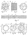
- Figures 1, 2, 3 show a laminated article, indicated overall by 1, comprising a plurality of mutually superposed metal laminations 2 (twenty-seven are shown in Figure 1), each comprising three coupling elements or clips 3 projecting from the surface of the laminations, and three though coupling cavities 6. More specifically, Figure 1 shows as the laminated article a conventional compensated rotor pack for electric motors. As is usual in conventional rotor packs, each lamination 2 comprises a series of profiled through cavities 4 provided along the outer edge, a central through hole 5, and the coupling clips 3. In the illustrated example these latter are of the angle plate type (as shown in Figure 4), but could also of of different type, for example of button, angled button or fin type.
- the coupling cavities 6 are arranged to house the clips 3 of the adjacent lamination. These cavities are preferably arranged symmetrically to each other along the same circumferential line L ( Figure 2) along which the clips 3 are formed, and all at the same angular distance B ( Figure 2) from the clips.
- the clips could also be arranged unsymmetrically to each other, and that the cavities 6 and clips 3 could be arranged along different circumferential lines, each circumferential line comprising at least one cavity and one clip, and such that all the cavities are at the same angular distance from the clips 3.
- the cavities 6 are through cavities, as shown in Figure 4. They could however also be shaped as a recessed female element, for housing the projecting portion of the clips 3.
- the cavities 6 can be dimensioned to engage the clips 3 with a certain clearance (as in Figure 4) or with greater contact, depending on the clamping requirements for the laminations and/or on the need to form spiralled articles.
- the cavities 6 are also advantageously provided in positions substantially adjacent to the clips 3, so that when a compensated article is to be formed, the laminations 2 being stacked are rotated one relative to the other only by the angle B ( Figure 2) between a clip 3 aid a cavity 6, and not by the angle C ( Figure 2) between one clip and the next, which happens if using known laminations. In this manner the overall time for stamping and stacking the article is considerably reduced.
- the cavities 6 can also be positioned and/or be in such a number as to enable the projecting part, suitably increased in height, to engage two underlying laminations, or penetrate two cavities in these laminations (see schematic Figures 4A and 4B).
- the end lamination or laminations 2A ( Figures 1, 3) of the laminated article do not comprise clips 3 but only cavities 6, to prevent two superposed articles becoming connected.
- the method for obtaining the laminations 2, 2A and for their stacking comprises a series of stamping stages carried out on a metal strip 7.
- a first stage the perimetral shaped through cavities 4 are formed (Figure 5A), in the next stage there being formed the coupling cavities, the central hole 5 and the clips 3 by deforming the strip ( Figure 5B).
- These stages can be concentrated into a single stage.
- the lamination 2 or 2A is die-cut from the strip ( Figure 5C).
- the die-cut lamination is stacked and then rotated through the compensation angle B together with the pack of laminations with which the lamination has been engaged.
- the aforedescribed method can be implemented by a usual progressive stamping device comprising a station for each of the aforelisted stages, and which in particular for the die-cutting third stage comprises a conventional rotary die 10. More specifically, the stamping device comprises stations which operate simultaneously on a metal strip 7 which advances periodically in a predetermined direction D ( Figure 5).
- the cavities 4 are formed in a first station ( Figure 5A), the cavities 6, the clips 3 and the hole being formed in a second station following the first, but with the facility for forming the cavities 4, the cavities 6, the clips 4 and the hole 5 in a single station or with a different distribution within the two stations.
- a lamination 2 or 2A is die-cut and stacked in a third station following the second, and is then rotated through the compensation angle. After the operations in each station have been completed the strip 7 is advanced through one step and the device proceeds with a further blow. It should be noted that in the third station the lamination is die-cut by a rotary die 10.
- the station for punching the clips 3 is modified by also being provided with punches for forming the coupling cavities 6, and by allowing the clip punching punches to be deactivated to leave those for the cavities 6 in operation. In this manner the same station can be used not only for forming usual laminations 2 but also for forming those laminations 2A for the end of the pack.
- the laminations of the invention result in more rigid packs. If for example laminations are used comprising two diametrically opposite clips and two cavities positioned along the same circumferential line as the clips but at 90° from this latter, the clips of the pack are no longer mutually aligned, as happens if using known laminations, but only the clips of two laminations every three are mutually aligned, ie the clips of the first lamination are out of alignment with those of the third, and the clips of the second are out of alignment with those of the fourth, and so on. It has been found that packs obtained in this manner are more rigid than traditional packs.
- the device could comprise separate stations for fuming the clips 3 and the coupling cavities 6 and also punches for cutting cavities 6 in correspondence with the clips 3 without deactivating the clip-forming punches.
- the punches used for forming the cavities 6 and clips 3 are advantageously different from each other, to enable the cavities to be dimensioned in the most suitable manner, taking account of the clamping and spiralling requirements of the article.
Landscapes
- Engineering & Computer Science (AREA)
- Power Engineering (AREA)
- Manufacturing & Machinery (AREA)
- Connection Of Plates (AREA)
- Iron Core Of Rotating Electric Machines (AREA)
- Laminated Bodies (AREA)
- Clamps And Clips (AREA)
- Medicines Containing Antibodies Or Antigens For Use As Internal Diagnostic Agents (AREA)
- Preparation Of Compounds By Using Micro-Organisms (AREA)
- Error Detection And Correction (AREA)
- Manufacture Of Motors, Generators (AREA)
Applications Claiming Priority (2)
| Application Number | Priority Date | Filing Date | Title |
|---|---|---|---|
| IT96MI002566A IT1286450B1 (it) | 1996-12-06 | 1996-12-06 | Articolo laminare comprendente elementi di accoppiamento del tipo a maschio-femmina |
| ITMI962566 | 1996-12-06 |
Publications (2)
| Publication Number | Publication Date |
|---|---|
| EP0847109A2 true EP0847109A2 (de) | 1998-06-10 |
| EP0847109A3 EP0847109A3 (de) | 1999-11-17 |
Family
ID=11375363
Family Applications (1)
| Application Number | Title | Priority Date | Filing Date |
|---|---|---|---|
| EP97118760A Withdrawn EP0847109A3 (de) | 1996-12-06 | 1997-10-29 | Lamellenförmiger Artikel mit männlichen-weiblichem Verbindungsglied |
Country Status (4)
| Country | Link |
|---|---|
| US (2) | US5923112A (de) |
| EP (1) | EP0847109A3 (de) |
| BR (1) | BR9706128A (de) |
| IT (1) | IT1286450B1 (de) |
Cited By (9)
| Publication number | Priority date | Publication date | Assignee | Title |
|---|---|---|---|---|
| WO1999066625A1 (en) * | 1998-06-19 | 1999-12-23 | General Electric Company | Paired interlocks for stacking of non-rotated lamination cores |
| WO2006096950A1 (en) * | 2005-03-17 | 2006-09-21 | Whirpool S.A. | Stack of metallic laminations and process for forming a lamination stack |
| EP1391975A4 (de) * | 2001-05-25 | 2007-03-21 | Mitsui High Tec | Laminierter kern und verfahren zur herstellung des laminierten kerns |
| WO2008040642A1 (de) * | 2006-10-04 | 2008-04-10 | Robert Bosch Gmbh | Blechpaket einer elektrischen maschine |
| EP1617542A4 (de) * | 2003-04-23 | 2011-06-29 | Mitsui High Tec | Schiefförmiger variabler laminierter eisenkernund verfahren zu seiner herstellung |
| ITMI20111153A1 (it) * | 2011-06-24 | 2012-12-25 | Eurotranciatura S P A | Pacco di lamierini per circuiti di macchine elettriche, con mezzi di connessione a graffa-sede |
| WO2012174629A2 (en) | 2011-06-22 | 2012-12-27 | Whirlpool S.A. | Stack of metallic laminations, metallic lamination and process for forming a lamination stack |
| EP2853317A1 (de) * | 2013-09-30 | 2015-04-01 | Wilhelm Schröder GmbH | Verfahren zur Herstellung eines Blechteils mit großer Wandstärke und dadurch hergestellter Blechteil |
| EP4462644A1 (de) * | 2023-04-19 | 2024-11-13 | Volkswagen Ag | Lamelle, lamellenpaket, verfahren zur herstellung eines lamellenpakets, elektrischer antrieb sowie kraftfahrzeug |
Families Citing this family (21)
| Publication number | Priority date | Publication date | Assignee | Title |
|---|---|---|---|---|
| US5809638A (en) * | 1992-10-26 | 1998-09-22 | L.H. Carbide Corporation | Method for manufacturing laminated parts with center interlock |
| JPH10304608A (ja) * | 1997-04-21 | 1998-11-13 | Hitachi Ltd | 電動機 |
| DE19818198A1 (de) * | 1998-04-23 | 1999-10-28 | Bosch Gmbh Robert | Verfahren zum Herstellen eines Läufers oder Ständers einer elektrischen Maschine aus Blechzuschnitten |
| DE19851217A1 (de) * | 1998-11-06 | 2000-05-11 | Bosch Gmbh Robert | Verfahren zum Herstellen eines Läufers oder Ständers einer elektrischen Maschine aus Blechzuschnitten |
| EP1133046A3 (de) * | 2000-03-02 | 2002-02-27 | Moriyama Kogyo Kabushiki Kaisha | Generator mit mehrpoliger magnetischer Erregung für Verbrennungskraftmaschinen |
| DE10203709A1 (de) * | 2001-02-02 | 2002-10-02 | Lg Electronics Inc | Verfahren zur Kernlamellierung in einem Motor und deren Lamellierungsbauweise |
| EP1504896B1 (de) * | 2001-12-25 | 2008-12-10 | Institute of Technology Precision Electrical Discharge Work's | Verfahren und system zur herstellung von laminat |
| DE10245691A1 (de) * | 2002-09-30 | 2004-04-08 | Robert Bosch Gmbh | Ständer für eine elektrische Maschine |
| JP4659441B2 (ja) * | 2004-11-29 | 2011-03-30 | 黒田精工株式会社 | 積層鉄心及びその製造方法 |
| JP4569542B2 (ja) * | 2006-02-13 | 2010-10-27 | 株式会社デンソー | 電磁スイッチ及びその製造方法 |
| ITMI20070508A1 (it) * | 2007-03-14 | 2008-09-15 | Corrada Spa | Articolo laminare per uso elettrico procedimento e macchine per realizzare detto articolo laminare |
| JP2009089223A (ja) * | 2007-10-02 | 2009-04-23 | Mitsubishi Electric Corp | 積層構造体 |
| ITMI20080674A1 (it) * | 2008-04-15 | 2009-10-16 | Morsettitalia Spa | Corpo conduttore multistrato e procedimento per la produzione dello stesso |
| US8410655B2 (en) * | 2008-08-07 | 2013-04-02 | Daikin Industries, Ltd. | Stator, motor, and compressor |
| JP6323030B2 (ja) * | 2014-01-24 | 2018-05-16 | 日産自動車株式会社 | ロータ |
| EP3002852A1 (de) * | 2014-09-30 | 2016-04-06 | Siemens Aktiengesellschaft | Rotor mit hineinragenden Stegen |
| JP6210058B2 (ja) * | 2014-12-26 | 2017-10-11 | Jfeスチール株式会社 | 積層鉄心用の打抜き加工方法及び積層鉄心の製造方法 |
| JPWO2019175930A1 (ja) * | 2018-03-12 | 2020-12-17 | 三菱電機株式会社 | 電動機の固定子及び電動機 |
| NL1043110B1 (en) * | 2018-12-24 | 2020-07-21 | Bosch Gmbh Robert | Process for manufacturing a laminate of stacked metal parts including a multi-layer blanking process step |
| DE102020128367B4 (de) | 2020-10-28 | 2025-10-30 | Te Connectivity Germany Gmbh | Anordnung mit einem aus mindestens drei aufeinanderliegenden Blechlagen zusammengefügten Blechstapel, elektrischer Kontakt umfassend diese Anordnung und Verfahren zum Durchsetzfügen eines Blechstapels |
| US20250392174A1 (en) * | 2022-12-30 | 2025-12-25 | Posco Mobility Solution Corporation | Laminated core and manufacturing method for the same |
Family Cites Families (15)
| Publication number | Priority date | Publication date | Assignee | Title |
|---|---|---|---|---|
| US4110895A (en) * | 1977-07-27 | 1978-09-05 | Mitsui Mfg. Co., Ltd. | Apparatus for manufacturing laminated cores |
| US4160182A (en) * | 1977-07-27 | 1979-07-03 | Mitsui Mfg. Co., Ltd. | Laminated core manufacture |
| US5087849A (en) * | 1983-03-25 | 1992-02-11 | L H Carbide Corporation | Laminated parts and a method for manufacture thereof |
| US4586236A (en) * | 1984-01-17 | 1986-05-06 | Penn United Technology, Inc. | Method and apparatus for forming stacks of laminated metallic members |
| DE3408563A1 (de) * | 1984-03-09 | 1985-09-19 | Kienle & Spiess Stanz- und Druckgießwerk GmbH, 7123 Sachsenheim | Stanzblechteil zur herstellung von blechpaketen fuer rotoren, statoren, magnetkerne und dergleichen |
| BG39784A1 (en) * | 1984-05-08 | 1986-08-15 | Popov | Inductor for electric machine |
| US4728842A (en) * | 1986-09-29 | 1988-03-01 | Carbet Corporation | Laminated assembly for a dynamoelectric machine and method for manufacturing laminated assemblies having ridges formed on projections which interlock with recesses of adjacent laminations |
| US5075150A (en) * | 1987-06-22 | 1991-12-24 | Linton And Hirst | Pack of laminations with projections and depressions in torsionally flexible contact |
| GB2226459B (en) * | 1988-12-23 | 1993-10-20 | Linton & Hirst Ltd | Packs of laminations and method and apparatus for forming them |
| US4979285A (en) * | 1990-07-20 | 1990-12-25 | Martin Benson D | Method of connecting a stack of laminations for electric motors |
| US5142178A (en) * | 1991-04-12 | 1992-08-25 | Emerson Electric Co. | Apparatus for aligning stacked laminations of a dynamoelectric machine |
| US5265320A (en) * | 1991-07-22 | 1993-11-30 | Greenway Glenn W | Metal stamping |
| JPH0614481A (ja) * | 1992-06-25 | 1994-01-21 | Mitsubishi Electric Corp | 電機子鉄心 |
| JPH08251901A (ja) * | 1995-03-03 | 1996-09-27 | Canon Inc | 電磁駆動装置 |
| JPH08275469A (ja) * | 1995-03-31 | 1996-10-18 | Hitachi Ltd | 積層鉄芯およびその製造方法 |
-
1996
- 1996-12-06 IT IT96MI002566A patent/IT1286450B1/it active IP Right Grant
-
1997
- 1997-10-29 EP EP97118760A patent/EP0847109A3/de not_active Withdrawn
- 1997-11-03 US US08/963,055 patent/US5923112A/en not_active Expired - Lifetime
- 1997-12-03 BR BR9706128A patent/BR9706128A/pt not_active IP Right Cessation
-
1998
- 1998-07-16 US US09/116,655 patent/US6009607A/en not_active Expired - Fee Related
Cited By (17)
| Publication number | Priority date | Publication date | Assignee | Title |
|---|---|---|---|---|
| WO1999066625A1 (en) * | 1998-06-19 | 1999-12-23 | General Electric Company | Paired interlocks for stacking of non-rotated lamination cores |
| US8048509B2 (en) | 2001-05-25 | 2011-11-01 | Mitsui High-Tec, Inc. | Laminated core and method of producing laminated core |
| EP1391975A4 (de) * | 2001-05-25 | 2007-03-21 | Mitsui High Tec | Laminierter kern und verfahren zur herstellung des laminierten kerns |
| EP1617542A4 (de) * | 2003-04-23 | 2011-06-29 | Mitsui High Tec | Schiefförmiger variabler laminierter eisenkernund verfahren zu seiner herstellung |
| US7768375B2 (en) | 2005-03-17 | 2010-08-03 | Whirlpool S.A. | Stack of metallic laminations and process for forming a lamination stack |
| CN101133540B (zh) * | 2005-03-17 | 2010-10-20 | 惠而浦股份有限公司 | 金属叠片堆、金属叠片和用于形成叠片堆的方法 |
| US7866030B2 (en) | 2005-03-17 | 2011-01-11 | Whirlpool S.A. | Process for forming a lamination stack |
| WO2006096950A1 (en) * | 2005-03-17 | 2006-09-21 | Whirpool S.A. | Stack of metallic laminations and process for forming a lamination stack |
| WO2008040642A1 (de) * | 2006-10-04 | 2008-04-10 | Robert Bosch Gmbh | Blechpaket einer elektrischen maschine |
| WO2012174629A2 (en) | 2011-06-22 | 2012-12-27 | Whirlpool S.A. | Stack of metallic laminations, metallic lamination and process for forming a lamination stack |
| WO2012174629A3 (en) * | 2011-06-22 | 2014-06-05 | Whirlpool S.A. | Stack of metallic laminations, metallic lamination and process for forming a lamination stack |
| US9768653B2 (en) | 2011-06-22 | 2017-09-19 | Whirlpool S. A. | Process for the formation of a stack of superposed metallic laminations |
| US10170948B2 (en) | 2011-06-22 | 2019-01-01 | Whirlpool S.A. | Process for the formation of a stack of superposed metallic laminations |
| US10411533B2 (en) | 2011-06-22 | 2019-09-10 | Embraco Industria de Compressores e Solucoes em Refrigeracao Ltda. | Process for the formation of a stack of superposed metallic laminations |
| ITMI20111153A1 (it) * | 2011-06-24 | 2012-12-25 | Eurotranciatura S P A | Pacco di lamierini per circuiti di macchine elettriche, con mezzi di connessione a graffa-sede |
| EP2853317A1 (de) * | 2013-09-30 | 2015-04-01 | Wilhelm Schröder GmbH | Verfahren zur Herstellung eines Blechteils mit großer Wandstärke und dadurch hergestellter Blechteil |
| EP4462644A1 (de) * | 2023-04-19 | 2024-11-13 | Volkswagen Ag | Lamelle, lamellenpaket, verfahren zur herstellung eines lamellenpakets, elektrischer antrieb sowie kraftfahrzeug |
Also Published As
| Publication number | Publication date |
|---|---|
| EP0847109A3 (de) | 1999-11-17 |
| US6009607A (en) | 2000-01-04 |
| MX9709083A (es) | 1998-07-31 |
| IT1286450B1 (it) | 1998-07-08 |
| ITMI962566A0 (it) | 1996-12-06 |
| ITMI962566A1 (it) | 1998-06-06 |
| BR9706128A (pt) | 1999-05-18 |
| US5923112A (en) | 1999-07-13 |
Similar Documents
| Publication | Publication Date | Title |
|---|---|---|
| US5923112A (en) | Laminated article comprising coupling elements of male-female type | |
| EP0508937B1 (de) | Vorrichtung und Verfahren um gestapelte Lamellen einer dynamo-elektrischen Maschine auszurichten | |
| US4149309A (en) | Laminated core manufacture | |
| US6000119A (en) | Lamina stack having a plurality of outer perimeter configurations and an apparatus and method for manufacturing said stack | |
| US4578853A (en) | Method of making a stack of electrical sheet-metal lamellae with aligned winding slots, particularly armatures for dynamo electric machines | |
| US6745458B2 (en) | Laminated magnetic core and method for making | |
| US4438558A (en) | Laminated core manufacturing apparatus | |
| US7062841B2 (en) | Method of manufacturing a formable laminated stack in a progressive die assembly having a choke | |
| JP4472417B2 (ja) | 積層鉄心の製造方法および金型装置 | |
| EP1120881A3 (de) | Verfahren zur Herstellung eines nutenden Stators | |
| US5255425A (en) | Method of manufacturing laminated core for dynamo-electric machine | |
| CN118174472B (zh) | 无铆点铁芯及其制造方法 | |
| US4280275A (en) | Apparatus for laminated core manufacture | |
| US3175277A (en) | Method of making stators | |
| US6195875B1 (en) | Apparatus for manufacturing long, slender lamina stacks from nonuniform laminae | |
| US4998430A (en) | Manufacture of rotor lamination for a dynamoelectric machine | |
| JP3964306B2 (ja) | 電動機の固定子積層鉄心の製造方法 | |
| US6636137B1 (en) | Ignition coil assembly | |
| JP4512655B2 (ja) | 積層鉄心の製造方法 | |
| JPH053648A (ja) | 電動機の固定子用積層鉄心及びその製造方法 | |
| EP0042047B1 (de) | Verfahren und Vorrichtung zur Herstellung eines geschichteten Rotors | |
| JPH0518655B2 (de) | ||
| CA1311515C (en) | Double-slope wedge | |
| JP2808555B2 (ja) | 積層鉄心の製造方法及びその装置 | |
| JP4991885B2 (ja) | 積層鉄心の製造方法 |
Legal Events
| Date | Code | Title | Description |
|---|---|---|---|
| PUAI | Public reference made under article 153(3) epc to a published international application that has entered the european phase |
Free format text: ORIGINAL CODE: 0009012 |
|
| AK | Designated contracting states |
Kind code of ref document: A2 Designated state(s): CH DE ES FR GB IT LI SE |
|
| AX | Request for extension of the european patent |
Free format text: AL;LT;LV;RO;SI |
|
| PUAL | Search report despatched |
Free format text: ORIGINAL CODE: 0009013 |
|
| AK | Designated contracting states |
Kind code of ref document: A3 Designated state(s): AT BE CH DE DK ES FI FR GB GR IE IT LI LU MC NL PT SE |
|
| AX | Request for extension of the european patent |
Free format text: AL;LT;LV;RO;SI |
|
| RIC1 | Information provided on ipc code assigned before grant |
Free format text: 6H 02K 15/02 A, 6H 02K 1/16 B, 6H 02K 1/26 B, 6H 01F 27/26 B, 6H 01F 27/245 B, 6H 01R 13/639 B |
|
| 17P | Request for examination filed |
Effective date: 20000503 |
|
| AKX | Designation fees paid |
Free format text: CH DE ES FR GB IT LI SE |
|
| AXX | Extension fees paid |
Free format text: SI PAYMENT 20000503 |
|
| 17Q | First examination report despatched |
Effective date: 20010321 |
|
| STAA | Information on the status of an ep patent application or granted ep patent |
Free format text: STATUS: THE APPLICATION IS DEEMED TO BE WITHDRAWN |
|
| 18D | Application deemed to be withdrawn |
Effective date: 20010801 |