EP0848176B1 - Embrayage à disque de friction humide - Google Patents
Embrayage à disque de friction humide Download PDFInfo
- Publication number
- EP0848176B1 EP0848176B1 EP97309930A EP97309930A EP0848176B1 EP 0848176 B1 EP0848176 B1 EP 0848176B1 EP 97309930 A EP97309930 A EP 97309930A EP 97309930 A EP97309930 A EP 97309930A EP 0848176 B1 EP0848176 B1 EP 0848176B1
- Authority
- EP
- European Patent Office
- Prior art keywords
- friction
- disc
- toothed disc
- discs
- grooves
- Prior art date
- Legal status (The legal status is an assumption and is not a legal conclusion. Google has not performed a legal analysis and makes no representation as to the accuracy of the status listed.)
- Expired - Lifetime
Links
- 239000002783 friction material Substances 0.000 claims description 61
- 239000010687 lubricating oil Substances 0.000 description 33
- 239000003921 oil Substances 0.000 description 24
- 230000013011 mating Effects 0.000 description 15
- 230000000694 effects Effects 0.000 description 7
- 230000005540 biological transmission Effects 0.000 description 3
- 230000033001 locomotion Effects 0.000 description 3
- 238000010008 shearing Methods 0.000 description 3
- 229910000831 Steel Inorganic materials 0.000 description 2
- 238000010521 absorption reaction Methods 0.000 description 2
- 238000007796 conventional method Methods 0.000 description 2
- 238000010586 diagram Methods 0.000 description 2
- 230000003068 static effect Effects 0.000 description 2
- 239000010959 steel Substances 0.000 description 2
- 238000001816 cooling Methods 0.000 description 1
- 230000007423 decrease Effects 0.000 description 1
- 230000003247 decreasing effect Effects 0.000 description 1
- 230000006866 deterioration Effects 0.000 description 1
- 230000008030 elimination Effects 0.000 description 1
- 238000003379 elimination reaction Methods 0.000 description 1
- 230000002708 enhancing effect Effects 0.000 description 1
- 230000020169 heat generation Effects 0.000 description 1
- 239000011148 porous material Substances 0.000 description 1
- 230000035939 shock Effects 0.000 description 1
- 238000004904 shortening Methods 0.000 description 1
Images



Classifications
-
- F—MECHANICAL ENGINEERING; LIGHTING; HEATING; WEAPONS; BLASTING
- F16—ENGINEERING ELEMENTS AND UNITS; GENERAL MEASURES FOR PRODUCING AND MAINTAINING EFFECTIVE FUNCTIONING OF MACHINES OR INSTALLATIONS; THERMAL INSULATION IN GENERAL
- F16D—COUPLINGS FOR TRANSMITTING ROTATION; CLUTCHES; BRAKES
- F16D13/00—Friction clutches
- F16D13/58—Details
- F16D13/60—Clutching elements
- F16D13/64—Clutch-plates; Clutch-lamellae
- F16D13/648—Clutch-plates; Clutch-lamellae for clutches with multiple lamellae
-
- F—MECHANICAL ENGINEERING; LIGHTING; HEATING; WEAPONS; BLASTING
- F16—ENGINEERING ELEMENTS AND UNITS; GENERAL MEASURES FOR PRODUCING AND MAINTAINING EFFECTIVE FUNCTIONING OF MACHINES OR INSTALLATIONS; THERMAL INSULATION IN GENERAL
- F16D—COUPLINGS FOR TRANSMITTING ROTATION; CLUTCHES; BRAKES
- F16D13/00—Friction clutches
- F16D13/58—Details
- F16D13/60—Clutching elements
- F16D13/64—Clutch-plates; Clutch-lamellae
-
- F—MECHANICAL ENGINEERING; LIGHTING; HEATING; WEAPONS; BLASTING
- F16—ENGINEERING ELEMENTS AND UNITS; GENERAL MEASURES FOR PRODUCING AND MAINTAINING EFFECTIVE FUNCTIONING OF MACHINES OR INSTALLATIONS; THERMAL INSULATION IN GENERAL
- F16D—COUPLINGS FOR TRANSMITTING ROTATION; CLUTCHES; BRAKES
- F16D13/00—Friction clutches
- F16D13/58—Details
- F16D13/72—Features relating to cooling
-
- F—MECHANICAL ENGINEERING; LIGHTING; HEATING; WEAPONS; BLASTING
- F16—ENGINEERING ELEMENTS AND UNITS; GENERAL MEASURES FOR PRODUCING AND MAINTAINING EFFECTIVE FUNCTIONING OF MACHINES OR INSTALLATIONS; THERMAL INSULATION IN GENERAL
- F16D—COUPLINGS FOR TRANSMITTING ROTATION; CLUTCHES; BRAKES
- F16D69/00—Friction linings; Attachment thereof; Selection of coacting friction substances or surfaces
- F16D2069/004—Profiled friction surfaces, e.g. grooves, dimples
Definitions
- the present invention pertains to the technical field of a friction disc clutch for use in automatic transmission or the like.
- a friction disc clutch is such that when a disc (friction disc) and a mating disc which are supported so as to rotate and to which friction materials are fixed, respectively, are pressed against each other, torque is transmitted by frictional force.
- the friction material usually has thermal insulating characteristic, so that the frictional heat is hardly transmitted to a disc on the back of the friction material, but is entirely transmitted to the mating disc. Therefore, in case of a "both sided" friction disc clutch formed by a combination of friction discs to which the friction materials are fixed on both faces and mating discs to which no friction materials are fixed, the friction discs do not contribute to the thermal absorption. That part of the total heat capacity of the friction disc clutch contributed by the friction discs is therefore wasted.
- US-Patent US-A-5 535 870 discloses a wet, multidisc friction clutch having alternatively arranged, interleaved discs, each disc consisting of a core plate and a friction member on only one face of the core plate.
- the friction members are engageable with the core plates of adjacent discs. Some of the friction members have a high coefficient of static friction for high torque transmission. Other friction members have a high coefficient of dynamic friction to reduce shock and noise upon engagement.
- the friction members having a high coefficient of static friction tend to have a relatively poor heat resistance. To counter this, the core plates which they engage are thicker than the core plates engaged by the other friction members, so that the heat generated upon engagement is different.
- the present invention provides a one-sided wet friction disc clutch comprising alternately arranged inside toothed discs and outside toothed discs to which friction materials and are respectively fixed on one side in the axial direction, characterised in that grooves are formed on the friction materials and on both of the inside toothed disc and the outside toothed disc and the pattern of the grooves on the inside toothed discs is different from that on the outside toothed discs.
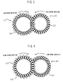
- Fig. 1 is a frontal view of an embodiment when an inside toothed disc rotates at higher speed than an outside toothed disc in a disengagement state.
- Fig. 2 is a frontal view of an embodiment when an outside toothed disc rotates at higher speed than an inside toothed disc in a disengagement state.
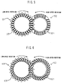
- Fig. 3 is a frontal view of a further embodiment when an outside toothed disc rotates at higher speed than an inside toothed disc in a disengagement state.
- Fig. 4 if a frontal view of a further embodiment when an inside toothed disc rotates at higher speed than an outside toothed disc in a disengagement state.
- Fig. 5 is a frontal view of a further embodiment when an inside toothed disc rotates at higher speed than an outside toothed disc in a disengagement state.
- Fig. 6 if a frontal view of a further embodiment when an inside toothed disc rotates at higher speed than an outside toothed disc in a disengagement state.
- Fig. 7 is a frontal view of a further embodiment when an inside toothed disc rotates at higher speed than an outside toothed disc in a disengagement state.
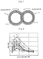
- Fig. 8 is a comparison diagram of drag torque in case of the embodiments of the invention and the conventional examples.
- Fig. 9 is an axial cross section of a one-sided wet friction disc clutch.
- Fig. 10 is a frontal view of a conventional combining structure of discs.
- Fig. 11 is a frontal view of another conventional combining structure of discs.
- a "one-sided” friction disc clutch as an object of the invention deals with the above mentioned problem of the "both sided” friction disc clutch, in which discs are not discriminated between the friction disc and the mating disc but one side of each disc to which the friction material is fixed functions as a friction material face and the other side functions as a mating face. Since all of the discs have consequently the heat absorption capability, the capacity of the friction disc clutch can be effectively used.
- a "one-sided" wet friction disc clutch 10 is shown in fig. 9.
- inside toothed discs 92 spline fitted into a hub 96 and outside toothed discs 93 spline fitted into a drum 97 are alternately arranged.
- Friction materials 921 and 931 are stuck to one side in the axial direction of the inside toothed discs 92 and the outside toothed discs 93, respectively.
- a hydraulic piston 98 is moved in the axial direction, the inside toothed discs 92 and the outside toothed discs 93 are engaged with each other and torque is transmitted.
- the inside toothed disc 92 and the outside toothed disc 93 rotate at different speeds.
- a disc connected to a drive side such as an engine rotates faster than a disc on a not-driven side.
- the friction material 921 on the inside toothed disc 92 faces a mating face generally made of a steel of the outside toothed disc 93 and a friction face 94 is formed between the friction material 921 and the mailing face via lubricating oil.
- the friction material 931 on the outside toothed disc 93 faces the mating face on the inside toothed disc 92 and a friction face 95 is formed between the friction material 931 and the mating face via the lubricating oil.
- the lubricating oil lying on the friction face is to be removed from the friction face to the outside in the radial direction by action of the centrifugal force by the rotating movement of the disc.
- the tendency becomes naturally stronger as the rotational speed increases.
- the moving speed of the lubricating oil lying on the friction face 94 is, consequently, lower than the moving speed of the lubricating oil lying on the friction face 95.
- the inside toothed disc 92 and the outside toothed disc 93 are positioned between the friction face 94 and the friction face 95, the inside toothed disc 92 and the outside toothed disc 93 tend to be deviatively positioned on the side of the friction face 94 at a lower pressure by the difference in pressure of the oil films formed on the friction faces.
- the moving speed of the lubricating oil lying on the friction face 95 is higher than the moving speed of the lubricating oil lying on the friction face 94.
- the inside toothed disc 92 and the outside toothed disc 93 tend to be deviatively positioned on the side of the friction face 95 at a lower pressure by the difference in pressure of oil films formed on the friction faces.
- the number of grooves is increased or decreased, the direction of inclination of the grooves is devised, and the like, thereby enhancing the removing performance of the oil on the friction face of the disc which rotates at lower speed.
- Figs. 1 to 7 show examples of combination of discs in which different patterned grooves are formed on the friction materials on the inside toothed discs and the outside toothed discs.
- Fig. 1 is a front view of discs such that, in a one-sided wet friction disc clutch in which an inside toothed disc 12 rotates at higher speed than an outside toothed disc 13 in a disengagement state, a friction material 131 on the outside toothed disc 12 which rotates at lower speed has a structure of grooves which are communicated from the inner diameter part to the outer diameter part and inclined so as to follow the rotational direction of the inside toothed disc, and a friction material 121 on the inside toothed disc 12 has a conventional groove structure shown in fig 10. "Follow the rotational direction” here denotes the direction which does not disturb the movement from the inside to the outside of oil when the oil given motion by the rotation receives centrifugal force.
- Fig. 2 is a front view of discs. in a "one-sided" wet friction disc clutch in which an outside toothed disc 23 rotates at higher speed than an inside toothed disc 22 in a disengagement state, a friction material 221 on the inside toothed disc 22 is provided with a structure of grooves communicated from the inner diameter part to the outer diameter part and inclined so as to follow the rotational direction of the outside toothed disc 23 and a friction material 231 on the outside toothed disc 23 is provided with the conventional groove structure shown in fig. 10.
- Discs in fig. 3 relate to a second embodiment of the inside toothed disc and the outside toothed disc used for a one-sided wet friction disc clutch under the same conditions as fig. 1.
- Grooves similar to those on the friction material 131 in fig. 1 are formed on a friction material 331 on an outside toothed disc 33 and grooves similar to those on the friction material of the conventional disc in fig. 11 are formed on a friction material 321 on an inside toothed disc 32. Effects are similar to those in case of fig. 1.
- Discs in fig. 4 relate to a second embodiment of the inside toothed disc and the outside toothed disc for use in a one-sided wet friction disc clutch under the same conditions as fig. 2.
- Discs in fig. 5 relate to a third embodiment of the inside toothed disc and the outside toothed disc for use in a one-sided wet friction disc clutch under the same conditions as fig. 1.
- the grooves shown in fig. 10 are formed on a friction material 521 on an inside toothed disc 52 and the grooves shown in fig. 11 are formed on a friction material 531 on an outside toothed disc 53.
- an area from which the lubricating oil is removed by the centrifugal force is enlarged, so that the removal by the centrifugal force is enlarged, so that the removal amount of the lubricating oil on the friction face 94 and that on the friction face 95 can be almost equalized irrespective of difference in rotational speed.
- Discs in fig. 6 relate to a fourth embodiment of the inside toothed disc and the outside toothed disc for use in a one-sided wet friction disc clutch under the same conditions as fig. 1.
- a friction material 631 on an outside toothed disc 63 is provided with a structure of grooves inclined so as to follow the rotational direction of the disc and a friction material 621 on an inside toothed disc 62 is provided with a structure of grooves inclined against the rotational direction of the disc contrary to the grooves of the friction material 631 on the outside toothed disc 63.
- Discs in fig. 7 relate to a third embodiment of the inside toothed disc and the outside toothed disc for use in a one-sided wet friction disc clutch under the same conditions as fig. 2.
- a friction material 721 on an inside toothed disc 72 is provided with the groove structure inclined so as to follow the rotational direction of the disc and a friction material 731 on an outside toothed disc 73 is provided with the groove structure inclined so as to be against the rotational direction of the disc contrary to the grooves of the friction material 721 on the inside toothed disc 72.
- Fig. 8 is a diagram showing the relation between relative rotational speed and drag torque with respect to the embodiments of the invention and the conventional examples for comparison.
- Numerals 1 to 7, 10 and 11 in fig. 8 show the relations between the relative rotational speed and the drag torque in the cases of using the discs shown in figs. 1 to 7, 10 and 11, respectively.
- the friction disc on which grooves following the rotation direction are formed has a high coefficient of friction in the early period of engagement and is very sticky and, on the contrary, the friction disc on which grooves against the rotational direction are formed has a low coefficient of friction in the early period of engagement and is not so sticky. Since the coefficient of friction in the early period of engagement is easily influenced by the shape of grooves formed on the friction disc, friction characteristics can be controlled by design of the shape of grooves on the friction disc. Therefore, according to the invention, the combinations of grooves as shown in figs. 1 to 7 can be selected according to desired friction characteristics.
- the groove shapes are combined according to the required friction characteristics, thereby enabling the friction characteristics to be controlled.
Landscapes
- Engineering & Computer Science (AREA)
- General Engineering & Computer Science (AREA)
- Mechanical Engineering (AREA)
- Mechanical Operated Clutches (AREA)
- Braking Arrangements (AREA)
Claims (5)
- Embrayage à disque de friction humide unilatéral (10) comprenant des disques dentés intérieurement (12,22,32,42,52,62,72) et des disques dentés extérieurement (13,23,33,43,53,63,73), qui sont disposés d'une manière alternée et auxquels sont fixés, respectivement sur une face dans la direction axiale, des matériaux de friction (121,221,321,421,521,621,721 et 131,231,331,431,531,631, 731), caractérisé en ce que des rainures sont formées dans les matériaux de friction (121,221,321,421,521,621,721 et 131,231,331,431,531,631,731) des deux côtés du disque denté intérieurement (12,22,32,42,52,62,72) et du disque denté extérieurement (13,23,33,43,53,63,73) et la configuration des rainures sur le disque denté intérieurement est différente de la configuration des rainures sur le disque denté extérieurement.
- Embrayage à disque à friction humide unilatéral selon la revendication 1, dans lequel le nombre de rainures dans le matériau de friction (131,221,331,421,521, 631,721) sur le disque (13,22,33,42,53,63,72), qui tourne à une vitesse inférieure à l'état désenclenché, est supérieur au nombre de rainures dans le matériau de friction (121,231,321,431,521,621,731) sur le disque (12,23,32, 43,52,62,73), qui tourne à une vitesse plus élevée.
- Embrayage à disque à friction humide unilatéral selon la revendication 1 ou 2, dans lequel le disque denté intérieurement (12,32,62) tourne à une vitesse plus élevée à l'état désenclenché, et des rainures qui mettent en communication la partie de diamètre intérieur avec la partie de diamètre extérieur formée sur le matériau de friction (131,331,631) sur le disque denté extérieurement (13,33,63) sont inclinées de manière à suivre le sens de rotation sur le disque denté intérieurement (12,32,62).
- Embrayage à disque à friction humide unilatéral selon la revendication 1 ou 2, dans lequel le disque denté extérieurement (23,43,73) tourne à une vitesse plus élevée à l'état désenclenché et des rainures qui mettent en communication la partie de diamètre intérieur avec la partie de diamètre extérieur formée sur le matériau de friction (221,421,721) sur le disque denté intérieurement (22,42,72) sont inclinées de manière à suivre le sens de rotation sur le disque denté intérieurement (23,43,73).
- Embrayage à disque à friction humide unilatéral selon la revendication 1 ou 2, dans lequel les rainures du matériau de friction (631,721) présent sur le disque (63,72), qui tourne à une vitesse inférieure à l'état désenclenché sont inclinées de manière à suivre la vitesse de rotation, et les rainures du matériau de friction (621,731) sur le disque (62,73), qui tourne à une vitesse plus élevée, sont inclinées de manière à être opposées au sens de rotation.
Applications Claiming Priority (3)
| Application Number | Priority Date | Filing Date | Title |
|---|---|---|---|
| JP8344479A JPH10169681A (ja) | 1996-12-10 | 1996-12-10 | 片貼り式湿式摩擦係合装置の摩擦板の組合わせ構造 |
| JP344479/96 | 1996-12-10 | ||
| JP34447996 | 1996-12-10 |
Publications (2)
| Publication Number | Publication Date |
|---|---|
| EP0848176A1 EP0848176A1 (fr) | 1998-06-17 |
| EP0848176B1 true EP0848176B1 (fr) | 2001-11-21 |
Family
ID=18369589
Family Applications (1)
| Application Number | Title | Priority Date | Filing Date |
|---|---|---|---|
| EP97309930A Expired - Lifetime EP0848176B1 (fr) | 1996-12-10 | 1997-12-09 | Embrayage à disque de friction humide |
Country Status (4)
| Country | Link |
|---|---|
| US (1) | US6135256A (fr) |
| EP (1) | EP0848176B1 (fr) |
| JP (1) | JPH10169681A (fr) |
| DE (1) | DE69708447T2 (fr) |
Families Citing this family (30)
| Publication number | Priority date | Publication date | Assignee | Title |
|---|---|---|---|---|
| DE19906980B4 (de) * | 1999-02-19 | 2013-09-19 | Borg-Warner Automotive Gmbh | Eingriffsteil für ein Kraftübertragungsaggregat |
| JP4108241B2 (ja) * | 1999-12-06 | 2008-06-25 | 本田技研工業株式会社 | 摩擦係合装置 |
| US6581740B2 (en) * | 2001-05-11 | 2003-06-24 | Visteon Global Technologies, Inc. | Multiple disc clutch pack having rheological film layer |
| JP2003042195A (ja) * | 2001-08-01 | 2003-02-13 | Nsk Warner Kk | ワンウェイクラッチ装置 |
| US7014024B2 (en) | 2003-06-11 | 2006-03-21 | Sulzer Euroflamm Us Inc. | System and method for improving cooling in a friction facing environment |
| US7069636B2 (en) | 2003-10-02 | 2006-07-04 | Euroflamm Select Inc. | Friction facing method for use in a friction environment |
| US7168544B2 (en) * | 2003-10-02 | 2007-01-30 | Sulzer Euroflamm Us Inc. | Friction facing material for use in a friction environment |
| US20060236523A1 (en) * | 2003-10-02 | 2006-10-26 | Sulzer Euroflamm Us Inc | Friction facing method for use in a friction environment |
| EP1731784B2 (fr) * | 2004-03-04 | 2014-03-05 | Kabushiki Kaisha F.C.C. | Disque de friction pour mecanisme d'embrayage de type huile |
| US7320391B2 (en) * | 2004-06-24 | 2008-01-22 | Raybestos Products Company | Alternative pack designs for multidisk clutches |
| US20070270069A1 (en) * | 2006-05-18 | 2007-11-22 | Sulzer Euroflamm Us Inc. | Friction material and system and method for making the friction material |
| DE102006031785A1 (de) * | 2006-07-10 | 2008-01-17 | Zf Friedrichshafen Ag | Lamellenkupplung oder Lamellenbremse mit axialer Öldurchströmung |
| JP2008138821A (ja) | 2006-12-05 | 2008-06-19 | Aisin Chem Co Ltd | 多板摩擦係合装置 |
| DE102008005227A1 (de) * | 2008-01-19 | 2009-07-23 | Dr. Ing. H.C. F. Porsche Aktiengesellschaft | Lamellenkupplung |
| JP4656211B2 (ja) | 2008-08-19 | 2011-03-23 | トヨタ自動車株式会社 | 摩擦係合装置 |
| IT1393806B1 (it) * | 2008-09-12 | 2012-05-11 | Ferrari Spa | Frizione multidisco in bagno d'olio |
| DE102008042124B4 (de) | 2008-09-16 | 2018-04-05 | Zf Friedrichshafen Ag | Nasslaufende Kopplungsanordnung |
| US20130186715A1 (en) * | 2012-01-23 | 2013-07-25 | Christopher A. MONROE | Separator plate for brake assembly |
| EP2932126B1 (fr) | 2012-12-14 | 2017-05-31 | Volvo Truck Corporation | Embrayage à disques multiples |
| WO2015046461A1 (fr) | 2013-09-26 | 2015-04-02 | アイシン・エィ・ダブリュ株式会社 | Embrayage |
| US10253823B2 (en) | 2014-05-22 | 2019-04-09 | Jatco Ltd | Cooling structure in clutch |
| KR20170121184A (ko) * | 2015-02-27 | 2017-11-01 | 섀플러 테크놀로지스 아게 운트 코. 카게 | 습식 작동 마찰 라이닝을 위한 라이닝 캐리어 |
| CN104895972B (zh) * | 2015-04-22 | 2017-07-25 | 安徽龙行密封件有限公司 | 一种离合器摩擦片组件 |
| AT518482B1 (de) | 2016-03-07 | 2018-08-15 | Miba Frictec Gmbh | Lamellenkupplung |
| DE112017001323T5 (de) * | 2016-03-16 | 2018-12-27 | Unipres Corporation | Nasse Mehrscheibenkupplung |
| JP6376671B1 (ja) * | 2017-04-04 | 2018-08-22 | 株式会社エフ・シー・シー | クラッチ摩擦板およびクラッチ装置 |
| CN109139733A (zh) * | 2018-11-09 | 2019-01-04 | 中国船舶重工集团公司第七0三研究所 | 一种高转速摩擦元件 |
| DE102019122482A1 (de) * | 2019-08-21 | 2021-02-25 | Knorr-Bremse Systeme für Nutzfahrzeuge GmbH | Kupplungsscheibe bzw. Reibscheibe, Kupplungsglocke sowie System aus Kupplungsscheibe bzw. Reibscheibe und Kupplungsglocke zum Bewirken einer Geräuschoptimierung |
| USD951064S1 (en) * | 2019-09-20 | 2022-05-10 | Caterpillar Inc. | Spacer |
| DE102024127922A1 (de) | 2024-09-26 | 2026-03-26 | Schaeffler Technologies AG & Co. KG | Lamellenbremse oder Lamellenkupplung mit Außenbeölung |
Citations (1)
| Publication number | Priority date | Publication date | Assignee | Title |
|---|---|---|---|---|
| US5535870A (en) * | 1995-04-13 | 1996-07-16 | Dynax Corporation | Wet multidisc friction engaging device |
Family Cites Families (19)
| Publication number | Priority date | Publication date | Assignee | Title |
|---|---|---|---|---|
| US1380823A (en) * | 1920-07-20 | 1921-06-07 | Armstrong Whitworth Co Eng | Clutch for turbine-driven geared propeller-shafts |
| US2743792A (en) * | 1951-10-11 | 1956-05-01 | Richard B Ransom | Rotary motion resisting device |
| US2850118A (en) * | 1956-02-23 | 1958-09-02 | Goodyear Tire & Rubber | Brake having a non-fusing brake element |
| US3063531A (en) * | 1958-11-12 | 1962-11-13 | Twin Disc Clutch Co | Friction plate clutch |
| DE1173740B (de) * | 1960-12-14 | 1964-07-09 | Held Ag Maschf | Reibungskupplung mit in OEl laufenden Lamellen |
| US3025686A (en) * | 1961-05-24 | 1962-03-20 | Robert P Lewis | Clutch discs |
| GB939720A (en) * | 1962-08-30 | 1963-10-16 | Twin Disc Clutch Co | Friction plate clutch |
| US4286694A (en) * | 1975-12-10 | 1981-09-01 | Goodyear Aerospace Corporation | Grooved carbon brake discs |
| DE2947242A1 (de) * | 1979-11-23 | 1981-05-27 | Fichtel & Sachs Ag, 8720 Schweinfurt | Hydraulisch betaetigbare reibungskupplung |
| JPS582425U (ja) * | 1981-06-30 | 1983-01-08 | 株式会社大金製作所 | クラツチデイスクのフエ−シング取付構造 |
| US5101953A (en) * | 1986-09-16 | 1992-04-07 | Borg-Warner Automotive Transmission & Engine Components Corporation | High capacity viscous pumping groove pattern for a wet clutch |
| US4958712A (en) * | 1987-06-29 | 1990-09-25 | Taiho Kogyo Co. Ltd. | Wet clutch device |
| US5094331A (en) * | 1988-03-18 | 1992-03-10 | Honda Giken Kogyo Kabushiki Kaisha | Wet-type multiplate clutch |
| JPH0419425A (ja) * | 1990-05-14 | 1992-01-23 | Nissan Motor Co Ltd | 湿式クラッチ |
| JPH04300427A (ja) * | 1990-05-16 | 1992-10-23 | Jatco Corp | 湿式摩擦締結要素 |
| US5176236A (en) * | 1992-01-09 | 1993-01-05 | Borg-Warner Automotive Transmission & Engine Components Corporation | Facing material for wet clutch plate and methods for fabricating and applying same |
| JPH0581249U (ja) * | 1992-01-31 | 1993-11-05 | 株式会社ダイナックス | 油膜排除効果を高めた形状の溝を具えた湿式摩擦材 |
| JP3020017B2 (ja) * | 1994-11-07 | 2000-03-15 | 大同メタル工業株式会社 | 湿式摩擦部材 |
| US5682971A (en) * | 1996-05-28 | 1997-11-04 | Dynax Corporation | Friction plate for high oil passage and cooling |
-
1996
- 1996-12-10 JP JP8344479A patent/JPH10169681A/ja active Pending
-
1997
- 1997-12-09 DE DE69708447T patent/DE69708447T2/de not_active Expired - Fee Related
- 1997-12-09 EP EP97309930A patent/EP0848176B1/fr not_active Expired - Lifetime
- 1997-12-10 US US08/988,430 patent/US6135256A/en not_active Expired - Fee Related
Patent Citations (1)
| Publication number | Priority date | Publication date | Assignee | Title |
|---|---|---|---|---|
| US5535870A (en) * | 1995-04-13 | 1996-07-16 | Dynax Corporation | Wet multidisc friction engaging device |
Also Published As
| Publication number | Publication date |
|---|---|
| DE69708447T2 (de) | 2002-06-27 |
| EP0848176A1 (fr) | 1998-06-17 |
| US6135256A (en) | 2000-10-24 |
| JPH10169681A (ja) | 1998-06-23 |
| DE69708447D1 (de) | 2002-01-03 |
Similar Documents
| Publication | Publication Date | Title |
|---|---|---|
| EP0848176B1 (fr) | Embrayage à disque de friction humide | |
| US6062367A (en) | Friction plate | |
| CA2386460C (fr) | Plaque de friction en bain d'huile | |
| JP3519114B2 (ja) | 摩擦ディスク | |
| US5048654A (en) | Ceramic clutch separator plates | |
| GB2065802A (en) | Friction lining for a multi-disc clutch or brake | |
| CA1305676C (fr) | Embrayage pour transmission a changement de vitesses continu | |
| EP0207685B1 (fr) | Dispositif d'embrayage de démarrage pour une transmission continue variable | |
| US6035991A (en) | Blocked slot clutch plate lining | |
| US5178249A (en) | Rotary coupling for torque transmission | |
| US5020646A (en) | Torque converter device | |
| CA1048427A (fr) | Systeme de refroidissement du mecanisme d'embrayage d'un vehicule | |
| EA000123B1 (ru) | Многодисковое соединительное устройство, автоматическая трансмиссия, снабженная этим устройством, и способ изготовления этого устройства | |
| JPH05231446A (ja) | 湿式多板クラッチ | |
| EP0191987B1 (fr) | Unité d'embrayage à démarrage actionnée hydrauliquement | |
| US4520912A (en) | Hydraulically actuated starting clutch assembly | |
| JPH07119755A (ja) | 湿式多板クラッチ | |
| US3648545A (en) | Differential clutch mechanism | |
| JPH0533787Y2 (fr) | ||
| JPH0419425A (ja) | 湿式クラッチ | |
| US5160008A (en) | Adjustable viscous shear coupling | |
| JPS5913139A (ja) | 遠心式多板クラツチ | |
| EP0841499B1 (fr) | Dispositif de transmission de force d'entraínement | |
| EP0608583A2 (fr) | Unité de transmission de couple à friction | |
| JPH0665895B2 (ja) | 可変速スリッピングクラッチ |
Legal Events
| Date | Code | Title | Description |
|---|---|---|---|
| PUAI | Public reference made under article 153(3) epc to a published international application that has entered the european phase |
Free format text: ORIGINAL CODE: 0009012 |
|
| AK | Designated contracting states |
Kind code of ref document: A1 Designated state(s): DE FR |
|
| AX | Request for extension of the european patent |
Free format text: AL;LT;LV;MK;RO;SI |
|
| 17P | Request for examination filed |
Effective date: 19980818 |
|
| AKX | Designation fees paid |
Free format text: DE FR |
|
| RBV | Designated contracting states (corrected) |
Designated state(s): DE FR |
|
| 17Q | First examination report despatched |
Effective date: 20001004 |
|
| GRAG | Despatch of communication of intention to grant |
Free format text: ORIGINAL CODE: EPIDOS AGRA |
|
| GRAG | Despatch of communication of intention to grant |
Free format text: ORIGINAL CODE: EPIDOS AGRA |
|
| GRAH | Despatch of communication of intention to grant a patent |
Free format text: ORIGINAL CODE: EPIDOS IGRA |
|
| GRAH | Despatch of communication of intention to grant a patent |
Free format text: ORIGINAL CODE: EPIDOS IGRA |
|
| GRAA | (expected) grant |
Free format text: ORIGINAL CODE: 0009210 |
|
| AK | Designated contracting states |
Kind code of ref document: B1 Designated state(s): DE FR |
|
| REF | Corresponds to: |
Ref document number: 69708447 Country of ref document: DE Date of ref document: 20020103 |
|
| PLBE | No opposition filed within time limit |
Free format text: ORIGINAL CODE: 0009261 |
|
| STAA | Information on the status of an ep patent application or granted ep patent |
Free format text: STATUS: NO OPPOSITION FILED WITHIN TIME LIMIT |
|
| 26N | No opposition filed | ||
| PGFP | Annual fee paid to national office [announced via postgrant information from national office to epo] |
Ref country code: FR Payment date: 20071130 Year of fee payment: 11 |
|
| PGFP | Annual fee paid to national office [announced via postgrant information from national office to epo] |
Ref country code: DE Payment date: 20071130 Year of fee payment: 11 |
|
| REG | Reference to a national code |
Ref country code: FR Ref legal event code: ST Effective date: 20090831 |
|
| PG25 | Lapsed in a contracting state [announced via postgrant information from national office to epo] |
Ref country code: DE Free format text: LAPSE BECAUSE OF NON-PAYMENT OF DUE FEES Effective date: 20090701 |
|
| PG25 | Lapsed in a contracting state [announced via postgrant information from national office to epo] |
Ref country code: FR Free format text: LAPSE BECAUSE OF NON-PAYMENT OF DUE FEES Effective date: 20081231 |