EP0848454A2 - Elektrischer Kontakt - Google Patents
Elektrischer Kontakt Download PDFInfo
- Publication number
- EP0848454A2 EP0848454A2 EP98101723A EP98101723A EP0848454A2 EP 0848454 A2 EP0848454 A2 EP 0848454A2 EP 98101723 A EP98101723 A EP 98101723A EP 98101723 A EP98101723 A EP 98101723A EP 0848454 A2 EP0848454 A2 EP 0848454A2
- Authority
- EP
- European Patent Office
- Prior art keywords
- contact
- section
- arms
- central section
- central
- Prior art date
- Legal status (The legal status is an assumption and is not a legal conclusion. Google has not performed a legal analysis and makes no representation as to the accuracy of the status listed.)
- Granted
Links
Images

Classifications
-
- H—ELECTRICITY
- H01—ELECTRIC ELEMENTS
- H01R—ELECTRICALLY-CONDUCTIVE CONNECTIONS; STRUCTURAL ASSOCIATIONS OF A PLURALITY OF MUTUALLY-INSULATED ELECTRICAL CONNECTING ELEMENTS; COUPLING DEVICES; CURRENT COLLECTORS
- H01R13/00—Details of coupling devices of the kinds covered by groups H01R12/70 or H01R24/00 - H01R33/00
- H01R13/02—Contact members
- H01R13/15—Pins, blades or sockets having separate spring member for producing or increasing contact pressure
- H01R13/18—Pins, blades or sockets having separate spring member for producing or increasing contact pressure with the spring member surrounding the socket
-
- H—ELECTRICITY
- H01—ELECTRIC ELEMENTS
- H01R—ELECTRICALLY-CONDUCTIVE CONNECTIONS; STRUCTURAL ASSOCIATIONS OF A PLURALITY OF MUTUALLY-INSULATED ELECTRICAL CONNECTING ELEMENTS; COUPLING DEVICES; CURRENT COLLECTORS
- H01R13/00—Details of coupling devices of the kinds covered by groups H01R12/70 or H01R24/00 - H01R33/00
- H01R13/02—Contact members
- H01R13/10—Sockets for co-operation with pins or blades
- H01R13/11—Resilient sockets
- H01R13/113—Resilient sockets co-operating with pins or blades having a rectangular transverse section
Definitions
- the subject of the invention relates to an improved electrical contact, and more particularly to an electrical contact that may be received in existing contact cavities and, in some cases, may be adapted for use in high vibration atmospheres.
- the connector housing includes a front face adapted to receive a tab-type terminal, and a socket terminal that is situated within the housing to receive the tab.
- the socket terminal includes two contact arms in opposing relation and extending forwardly to a constricted portion for receiving the tab therebetween and exerting a normal force thereupon.
- four axially extending ribs are positioned in each corner of the housing on the inside of the contact passageway.
- EP-A-0 363 170 and JP-UM-Pub. No. 7014/85 disclose an electrical contact having opposing contact arms that extend from a contact body where the contact arms are supported by transversely disposed arms that are joined to the contact arms at a location spaced from the contact body.
- EP-A-0 433 610 discloses an electrical contact having a central section, a front contact section and a conductor engaging section.
- a locking lance extends in a cantilevered manner from the central section and is resiliently connected thereto such that as the contact is inserted into a housing the locking lance deflects upon passing a shoulder and then resiles to engage the shoulder to prevent withdrawal.
- EP-A-0 433 610 discloses an electrical contact having a central section, a front contact section and a conductor engaging section where the front contact section includes a pair of opposed contact arms configured for receiving a tab therebetween.
- the contact arms have a width less than the width of a side of the central section from which they originate.
- An outer box is provided about the central section and includes a tongue member extending over the contact arms to provide support thereto.
- the contact will fit into a previously established connector contact cavity. It is an advantage of another aspect of the invention that the front contact portion may float relative the wire section so that fretting corrosion is prevented.
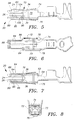
- the inner contact includes a central section 6 with individual box shapes 8,10 and 12 that are interconnected by web members 14 and 16, thereby allowing longitudinal movement of the front contact section 20 relative to the wire crimp section 22.
- two contact arms 24 extend forwardly from the box member 12 while two contact arms 26 extend forwardly from a lower portion of the box member 12 and are opposed to contact arms 24.
- Contact arms 24 and 26 are constricted at 28 and 30, thereby forming a receiving section for a tab of a mating contact (not shown).
- Arms 34 and 36 as shown in Figure 1 and 2 respectively, also extend from the box member 12 and extend forwardly to L-shaped portions 40 and 42 where they are interconnected with the respective contact arms 24,26, as best shown in Figure 4.
- the contact arms 24 and 26 have a width W1
- the box member 12 has a width W2.
- the arms 34 and 36 are folded about the L-shaped sections 40 to lie adjacent to the side edges of the contact arms 26 in a transverse manner such that the contact arms are supported by a beam having a relevant dimension greater than the thickness of the material.
- the front contact section presents the narrowed width by necking the arms inward and being narrowed through transition zones 44, 46. This presents a nose that will fit into an existing cavity with a body substantial enough to incorporate the necessary features such as box closure, locking lances and secondary locking shoulders.
- the side walls 50 which extend rearwardly from the section 8 have upper edges at 52 having locking barbs at 54 as will be described in greater detail herein.
- the base section 56 includes an opening at 58 thereby forming a rearwardly facing edge 60 from the section 8, also which will be described in greater detail herein.
- an outer assist spring is shown at 70 including side walls 72,73; a top wall 74; and a lower wall 75.
- the outer assist spring 70 may carry a set of locking lances to retain the contact within a terminal cavity of a connector housing (not shown).
- a rear portion of the assist spring 70 includes crimp sections 78 which are crimped around the upper edge 52 forward of the barb sections 54 to maintain the assist spring in secure position on the inner contact 2. It should be appreciated that the outer assist spring 70 is clinched to the rear portion of the inner contact 2 which is fixed, thereby allowing the forward contact section 20 to be longitudinally moveable within the assist spring 70 relative the wire section 22.
- Forwardly extending arms 84 and 85 extend from walls 74 and 75 respectively.
- the arms 84 and 85 do not contact the contact arms 24 and 26, but rather are spaced apart to allow the longitudinal movement of the forward spring member 20.
- the arms 84 and 85 are contoured to overly, at substantially the same width as, the contact arms 24 and 26. This is accomplished by the outer assist spring 70 including a transition section at 84,86, thereby forming a contoured spring arm 84.
- each outer edge of the spring arms 84 include folded-over tab sections 94 and 95 are spaced from respective edges 104 and 105 of the spring arms 34.
- the opposite side of the spring arms 84 and 85 also include tab members 94 and 95.
- the forward free ends of the arms 84 and 85 include inwardly directed sections at 88 and 89 spaced from the contact spring arms 24 and 26 respectively.
- the transition sections 44 and 46 of the inner contact 2 provide a compact inner front contact section at 20 having a substantially square cross section as shown in Figure 4. Even though the spring arms 24 and 26 are narrowed to a distance W1, the contact arms are rigidified through the arms 34 and 36 which are integrally interconnected through the L-shaped free end portions at 40. Furthermore, the contact member 2 includes longitudinally moveable sections 8, 10 and 12 thereby allowing the section 8 to be maintained in a fixed position while the contact section 20 can move forwardly and rearwardly relative thereto. The front contact section 20 is moveable within the assist spring member 70, and the movement of the contact spring is guarded by the safety features provided by the outer assist spring.
- the tab members 94 and 95 prevent over-stressing of the contact arms 24 and 26, such that if the arms 24 and 26 expand too far outwardly, the edges 104 and 105 of the side arm springs 34 will contact the tab portions 94 and 95 preventing over-stressing thereof. Furthermore, the front end section 88 and 89 prevent over-stressing of the forward contact section 20 along the longitudinal axis by preventing displacement too far inwardly.
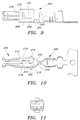
- the contact 202 has a central section 206 comprised of a lower wall 208 sidewalls 210 and 212 and top cover halves 214 and 216.
- the cover halves include complementary dovetail tab and slot 218, 220 features that join the contact together along the longitudinal axis. It is envisioned that other know techniques may be advantageous.
- the front contact section 220 of this embodiment is virtually identical to the front contact section 20 of the embodiment of Figures 1-8, thereby enabling this contact to recognize the aforegoing advantages.
- the contact section 220 of this contact is not longitudinally moveable relative to the wire crimp section 222.
- the locking lances 230 are integral with the side walls 210 and 212 of the central section 206.
- the locking lances 230 are formed such that they extend from a band section 232 in a cantilevered manner.
- the band section 232 is defined by a sheared line segment at 234 that is spaced from the location from which the locking lance 230 is cantilevered, as best seen in Figure 9.
- sheared line segment may actually be a series of segments, interconnected if desired to form a path other than straight, such as a curve, a chevron, or a louver-like structure having multiple short slits to define the overall segment.
- the band section 232 enables a short stiff locking lance 230 to be incorporated into a contact where it would normally not be possible due to the required length of the lance.
- a locking lance must be sufficiently long to assure that for the material chosen the lance will undergo resilient and not plastic deformation as the contact is inserted into the connector housing to assure the locking lance after being deflected will be able return to a position for engaging the backside of a shoulder after being passed thereby.
- the band section 232 which has some flexibility, the locking lance 230 is torsionally moveable about the band portion 232. Furthermore, the additional flexibility of the band section 232 aids in the dampening of relative vibration between the mating contacts. Note, construction of this type may also be incorporated into contacts of any configuration and may be incorporated into other parts of a contact which carry the locking lance, such as an outer back-up spring. Therefore, the term central section of the contact means that part of the contact which carries the locking lance and this invention should not be limited by the embodiment depicted.
- the contact is constricted along arms 240 and includes a cutout section at 242, thereby allowing a stiff locking surface at 244.
- the arms 240 extend approximately symmetrically from the central section forming an upper surface similar to locking surface 244.
Landscapes
- Connector Housings Or Holding Contact Members (AREA)
- Manufacturing Of Electrical Connectors (AREA)
Applications Claiming Priority (3)
| Application Number | Priority Date | Filing Date | Title |
|---|---|---|---|
| GB9405303 | 1994-03-17 | ||
| GB9405303A GB9405303D0 (en) | 1994-03-17 | 1994-03-17 | Electrical contact |
| EP95914484A EP0750799B1 (de) | 1994-03-17 | 1995-03-07 | Elektrisches kontaktglied |
Related Parent Applications (1)
| Application Number | Title | Priority Date | Filing Date |
|---|---|---|---|
| EP95914484A Division EP0750799B1 (de) | 1994-03-17 | 1995-03-07 | Elektrisches kontaktglied |
Publications (3)
| Publication Number | Publication Date |
|---|---|
| EP0848454A2 true EP0848454A2 (de) | 1998-06-17 |
| EP0848454A3 EP0848454A3 (de) | 1998-07-08 |
| EP0848454B1 EP0848454B1 (de) | 2006-10-11 |
Family
ID=10752062
Family Applications (2)
| Application Number | Title | Priority Date | Filing Date |
|---|---|---|---|
| EP98101723A Expired - Lifetime EP0848454B1 (de) | 1994-03-17 | 1995-03-07 | Elektrischer Kontakt |
| EP95914484A Expired - Lifetime EP0750799B1 (de) | 1994-03-17 | 1995-03-07 | Elektrisches kontaktglied |
Family Applications After (1)
| Application Number | Title | Priority Date | Filing Date |
|---|---|---|---|
| EP95914484A Expired - Lifetime EP0750799B1 (de) | 1994-03-17 | 1995-03-07 | Elektrisches kontaktglied |
Country Status (5)
| Country | Link |
|---|---|
| US (1) | US5755599A (de) |
| EP (2) | EP0848454B1 (de) |
| DE (2) | DE69504481T2 (de) |
| GB (1) | GB9405303D0 (de) |
| WO (1) | WO1995025362A1 (de) |
Cited By (3)
| Publication number | Priority date | Publication date | Assignee | Title |
|---|---|---|---|---|
| EP0821437B1 (de) * | 1996-07-25 | 2003-11-19 | Sumitomo Wiring Systems, Ltd. | Kontaktbüchsearmatur |
| DE19961544B4 (de) * | 1998-12-21 | 2009-03-05 | The Whitaker Corp., Wilmington | Elektrischer Buchsenkontakt |
| DE10320541B4 (de) * | 2002-05-07 | 2012-11-29 | Lear Corp. | Elektrisches Kontaktelement |
Families Citing this family (29)
| Publication number | Priority date | Publication date | Assignee | Title |
|---|---|---|---|---|
| GB9406929D0 (en) * | 1994-04-07 | 1994-06-01 | Amp Gmbh | Electrical contact having improved secondary locking surfaces |
| DE19536500C2 (de) * | 1995-09-29 | 1997-07-24 | Siemens Ag | Buchsenkontakt mit Grund- und Überfeder |
| DE19618928B4 (de) * | 1996-05-10 | 2006-04-06 | The Whitaker Corp., Wilmington | Buchsenartiger elektrischer Kontakt und Gehäuse für einen solchen Kontakt |
| US5890936A (en) * | 1996-10-15 | 1999-04-06 | Ut Automotive Dearborn, Inc. | Electrical terminal |
| JP3402435B2 (ja) * | 1997-05-09 | 2003-05-06 | 住友電装株式会社 | プリント基板用コネクタ |
| ES1039053Y (es) * | 1997-12-17 | 1999-03-16 | Mecanismos Aux Ind | Terminal hembra perfeccionado. |
| EP1006613B1 (de) | 1998-12-01 | 2003-08-06 | Thomas & Betts International, Inc. | Verbesserter Messerkontaktsteckverbinder bestehend aus zwei Teilen |
| DE19918326A1 (de) * | 1999-04-22 | 2000-10-26 | Delphi Tech Inc | Elektrische Anschlußbuchse |
| EP1122832A3 (de) * | 2000-01-31 | 2001-09-26 | Tyco Electronics AMP GmbH | Kontaktbuchse |
| EP1122831A3 (de) * | 2000-01-31 | 2001-09-26 | Tyco Electronics AMP GmbH | Kontaktbuchse |
| EP1146594A3 (de) * | 2000-04-13 | 2003-01-02 | Tyco Electronics France SAS | Verbinder zum Kontaktieren eines Pols einer Batterie, insbesondere einer 42 Volt-Batterie |
| EP1215763B2 (de) * | 2000-10-12 | 2007-12-05 | Tyco Electronics AMP GmbH | Kontaktbuchse für eine elektrische Steckverbindung |
| US6626708B2 (en) | 2001-03-30 | 2003-09-30 | Tyco Electronics Corporation | Single piece spring contact |
| EP1764869A3 (de) * | 2005-09-16 | 2008-01-23 | Gebauer & Griller Kabelwerke Gesellschaft m.b.H. | Anschlussklemme |
| JP2010055937A (ja) | 2008-08-28 | 2010-03-11 | Sumitomo Wiring Syst Ltd | 端子金具及び端子金具付き電線 |
| US8998655B2 (en) | 2012-09-24 | 2015-04-07 | Lear Corporation | Electrical terminal |
| DE102013013633A1 (de) | 2012-09-24 | 2014-04-10 | Lear Corp. | Elektrischer Anschluss |
| DE102013013632A1 (de) | 2012-09-26 | 2014-04-10 | Lear Corp. | Elektrischer Anschluss |
| WO2014063142A1 (en) | 2012-10-19 | 2014-04-24 | Lear Corporation | Electrical terminal |
| DE102014009208B4 (de) | 2013-06-21 | 2018-08-09 | Lear Corporation | Elektrische anschlussanordnung |
| US9444205B2 (en) | 2014-03-25 | 2016-09-13 | Lear Corporation | Electric connector with contact protection |
| US10128602B2 (en) | 2014-05-13 | 2018-11-13 | Lear Corporation | Electric connector with a terminal interface |
| US9847591B2 (en) | 2014-07-22 | 2017-12-19 | Lear Corporation | Electric terminal assembly |
| JP6405235B2 (ja) | 2014-12-29 | 2018-10-17 | モレックス エルエルシー | 雌型電気端子、及びコネクタ |
| KR101803530B1 (ko) | 2016-09-19 | 2017-12-01 | 이경현 | 분리형 접속핀을 구비한 커넥터 |
| CN110313110B (zh) * | 2017-03-01 | 2021-02-05 | 莫列斯有限公司 | 电端子以及连接器组件 |
| CN112350092B (zh) * | 2019-08-08 | 2023-07-18 | 上海莫仕连接器有限公司 | 连接器及端子 |
| TWI734244B (zh) * | 2019-11-04 | 2021-07-21 | 大陸商東莞訊滔電子有限公司 | 電性端子以及電連接器 |
| DE102020133731B3 (de) * | 2020-12-16 | 2022-03-31 | Lisa Dräxlmaier GmbH | Elektrisches kontaktteil |
Family Cites Families (15)
| Publication number | Priority date | Publication date | Assignee | Title |
|---|---|---|---|---|
| DE1952925C3 (de) * | 1969-10-21 | 1974-11-14 | Hans 5463 Unkel Simon | Isoliergehäuse für mit Haltehaken versehene Flachsteckkontakte |
| DE8236405U1 (de) * | 1982-12-24 | 1984-10-04 | Grote & Hartmann Gmbh & Co Kg, 5600 Wuppertal | Doppelflachfederkontakt mit Überfeder |
| JPS607014A (ja) * | 1983-06-24 | 1985-01-14 | 昭和電線電纜株式会社 | Nb↓3Sn超電導線の製造方法 |
| DE3424072A1 (de) * | 1984-06-29 | 1986-01-09 | Grote & Hartmann | Steckverbinder |
| IT1179895B (it) * | 1984-12-28 | 1987-09-16 | Burndy Electra Spa | Elemento di contatto elettrico femmina con sforzo di accoppiamento relativamente ridotto e relativo complesso connettore |
| DE8713038U1 (de) * | 1987-09-28 | 1987-11-19 | Amp Deutschland Gmbh, 6070 Langen | Buchsenartiger elektrischer Anschluß |
| US4907990A (en) * | 1988-10-07 | 1990-03-13 | Molex Incorporated | Elastically supported dual cantilever beam pin-receiving electrical contact |
| US4900271A (en) * | 1989-02-24 | 1990-02-13 | Molex Incorporated | Electrical connector for fuel injector and terminals therefor |
| DE8914951U1 (de) * | 1989-12-18 | 1991-04-18 | Grote & Hartmann Gmbh & Co Kg, 5600 Wuppertal | Elektrisches Kontaktelement mit einer Überfeder |
| US5209680A (en) * | 1992-01-10 | 1993-05-11 | Molex Incorporated | Male electrical terminal with anti-overstress means |
| GB9208205D0 (en) * | 1992-04-14 | 1992-05-27 | Amp Gmbh | Electrical socket terminal |
| DE9211819U1 (de) * | 1992-07-07 | 1993-11-04 | Grote & Hartmann | Elektrisches Kontaktelement |
| DE4235245C2 (de) * | 1992-10-20 | 2002-07-11 | Bosch Gmbh Robert | Elektrische Steckverbindung |
| GB9225885D0 (en) * | 1992-12-11 | 1993-02-03 | Amp Gmbh | Vibration proof electrical receptacle |
| GB9406934D0 (en) * | 1994-04-07 | 1994-06-01 | Amp Gmbh | Electrial terminal back-up spring with anti-chattering support members |
-
1994
- 1994-03-17 GB GB9405303A patent/GB9405303D0/en active Pending
-
1995
- 1995-03-07 DE DE69504481T patent/DE69504481T2/de not_active Expired - Lifetime
- 1995-03-07 DE DE69535265T patent/DE69535265T2/de not_active Expired - Lifetime
- 1995-03-07 EP EP98101723A patent/EP0848454B1/de not_active Expired - Lifetime
- 1995-03-07 WO PCT/IB1995/000140 patent/WO1995025362A1/en not_active Ceased
- 1995-03-07 US US08/704,533 patent/US5755599A/en not_active Expired - Fee Related
- 1995-03-07 EP EP95914484A patent/EP0750799B1/de not_active Expired - Lifetime
Cited By (3)
| Publication number | Priority date | Publication date | Assignee | Title |
|---|---|---|---|---|
| EP0821437B1 (de) * | 1996-07-25 | 2003-11-19 | Sumitomo Wiring Systems, Ltd. | Kontaktbüchsearmatur |
| DE19961544B4 (de) * | 1998-12-21 | 2009-03-05 | The Whitaker Corp., Wilmington | Elektrischer Buchsenkontakt |
| DE10320541B4 (de) * | 2002-05-07 | 2012-11-29 | Lear Corp. | Elektrisches Kontaktelement |
Also Published As
| Publication number | Publication date |
|---|---|
| US5755599A (en) | 1998-05-26 |
| EP0848454B1 (de) | 2006-10-11 |
| DE69504481T2 (de) | 1999-02-25 |
| WO1995025362A1 (en) | 1995-09-21 |
| GB9405303D0 (en) | 1994-04-27 |
| DE69504481D1 (de) | 1998-10-08 |
| EP0848454A3 (de) | 1998-07-08 |
| EP0750799A1 (de) | 1997-01-02 |
| DE69535265T2 (de) | 2007-05-24 |
| EP0750799B1 (de) | 1998-09-02 |
| DE69535265D1 (de) | 2006-11-23 |
Similar Documents
| Publication | Publication Date | Title |
|---|---|---|
| EP0848454B1 (de) | Elektrischer Kontakt | |
| US5975964A (en) | Female terminal fitting | |
| EP1351338B1 (de) | Anschlusskontakt | |
| US7530859B2 (en) | Electrical contact | |
| EP0727842B1 (de) | Einstückige Ansschlussbüchse | |
| EP0688065B1 (de) | Elektrische Buchse | |
| US5941740A (en) | Electrical terminal | |
| EP1120861B1 (de) | Elektrischer Verbinder mit verbesserter Kontaktbüchse | |
| EP0677890A1 (de) | Unterstützungsfeder eines elektrischen Verbinders mit anti-Ratter Stützorganen | |
| EP1104051B1 (de) | Verbinder | |
| JP2005505104A (ja) | 自動車用大電流電気コネクタ及び端子 | |
| JPH07307180A (ja) | リセプタクル型コンタクト | |
| EP0935827B1 (de) | Kontakt mit verriegelung zur kontakthalterung und dafür geeignetes gehaüse | |
| EP0726615A2 (de) | Elektrischer Kontakt | |
| EP0697752A2 (de) | Elektrische Anschlussbuchse | |
| EP0687033A2 (de) | Buchsenklemme für Hochstrom | |
| US5890936A (en) | Electrical terminal | |
| EP0178102A2 (de) | Elektrische Anschlussklemmen und Steckverbinderzusammenstellungen | |
| EP0700122B1 (de) | Elektrische Buchse | |
| EP0676827A2 (de) | Elektrischer Kontakt mit verbesserten zweiten Verriegelungsflächen | |
| US5122083A (en) | Resilient terminal with buckling prevention mechanism | |
| EP0727843B1 (de) | Asymmetrisches elektrisches Kontaktgehäuse | |
| US5197906A (en) | Resilient terminal with buckling prevention mechanism | |
| EP0736930B1 (de) | Kontakt mit einem unabhängig unterstützten inneren Kontaktarm | |
| EP0847104B1 (de) | Steckerelement |
Legal Events
| Date | Code | Title | Description |
|---|---|---|---|
| PUAI | Public reference made under article 153(3) epc to a published international application that has entered the european phase |
Free format text: ORIGINAL CODE: 0009012 |
|
| PUAL | Search report despatched |
Free format text: ORIGINAL CODE: 0009013 |
|
| AC | Divisional application: reference to earlier application |
Ref document number: 750799 Country of ref document: EP |
|
| AK | Designated contracting states |
Kind code of ref document: A2 Designated state(s): DE FR GB |
|
| AK | Designated contracting states |
Kind code of ref document: A3 Designated state(s): DE FR GB |
|
| 17P | Request for examination filed |
Effective date: 19990210 |
|
| GRAP | Despatch of communication of intention to grant a patent |
Free format text: ORIGINAL CODE: EPIDOSNIGR1 |
|
| GRAS | Grant fee paid |
Free format text: ORIGINAL CODE: EPIDOSNIGR3 |
|
| GRAA | (expected) grant |
Free format text: ORIGINAL CODE: 0009210 |
|
| AC | Divisional application: reference to earlier application |
Ref document number: 0750799 Country of ref document: EP Kind code of ref document: P |
|
| AK | Designated contracting states |
Kind code of ref document: B1 Designated state(s): DE FR GB |
|
| RAP1 | Party data changed (applicant data changed or rights of an application transferred) |
Owner name: THE WHITAKER CORPORATION |
|
| REG | Reference to a national code |
Ref country code: GB Ref legal event code: FG4D |
|
| REF | Corresponds to: |
Ref document number: 69535265 Country of ref document: DE Date of ref document: 20061123 Kind code of ref document: P |
|
| ET | Fr: translation filed | ||
| PLBE | No opposition filed within time limit |
Free format text: ORIGINAL CODE: 0009261 |
|
| STAA | Information on the status of an ep patent application or granted ep patent |
Free format text: STATUS: NO OPPOSITION FILED WITHIN TIME LIMIT |
|
| 26N | No opposition filed |
Effective date: 20070712 |
|
| PGFP | Annual fee paid to national office [announced via postgrant information from national office to epo] |
Ref country code: FR Payment date: 20130405 Year of fee payment: 19 Ref country code: DE Payment date: 20130327 Year of fee payment: 19 Ref country code: GB Payment date: 20130327 Year of fee payment: 19 |
|
| REG | Reference to a national code |
Ref country code: DE Ref legal event code: R119 Ref document number: 69535265 Country of ref document: DE |
|
| GBPC | Gb: european patent ceased through non-payment of renewal fee |
Effective date: 20140307 |
|
| REG | Reference to a national code |
Ref country code: FR Ref legal event code: ST Effective date: 20141128 |
|
| REG | Reference to a national code |
Ref country code: DE Ref legal event code: R119 Ref document number: 69535265 Country of ref document: DE Effective date: 20141001 |
|
| PG25 | Lapsed in a contracting state [announced via postgrant information from national office to epo] |
Ref country code: GB Free format text: LAPSE BECAUSE OF NON-PAYMENT OF DUE FEES Effective date: 20140307 Ref country code: DE Free format text: LAPSE BECAUSE OF NON-PAYMENT OF DUE FEES Effective date: 20141001 Ref country code: FR Free format text: LAPSE BECAUSE OF NON-PAYMENT OF DUE FEES Effective date: 20140331 |