EP0848512A2 - Méthode pour et système de communication entre des points le long de l'écoulement d'un fluide - Google Patents
Méthode pour et système de communication entre des points le long de l'écoulement d'un fluide Download PDFInfo
- Publication number
- EP0848512A2 EP0848512A2 EP97309696A EP97309696A EP0848512A2 EP 0848512 A2 EP0848512 A2 EP 0848512A2 EP 97309696 A EP97309696 A EP 97309696A EP 97309696 A EP97309696 A EP 97309696A EP 0848512 A2 EP0848512 A2 EP 0848512A2
- Authority
- EP
- European Patent Office
- Prior art keywords
- data
- remotely
- storage units
- point
- data storage
- Prior art date
- Legal status (The legal status is an assumption and is not a legal conclusion. Google has not performed a legal analysis and makes no representation as to the accuracy of the status listed.)
- Withdrawn
Links
Images

Classifications
-
- H—ELECTRICITY
- H04—ELECTRIC COMMUNICATION TECHNIQUE
- H04B—TRANSMISSION
- H04B13/00—Transmission systems characterised by the medium used for transmission, not provided for in groups H04B3/00 - H04B11/00
-
- E—FIXED CONSTRUCTIONS
- E21—EARTH OR ROCK DRILLING; MINING
- E21B—EARTH OR ROCK DRILLING; OBTAINING OIL, GAS, WATER, SOLUBLE OR MELTABLE MATERIALS OR A SLURRY OF MINERALS FROM WELLS
- E21B47/00—Survey of boreholes or wells
- E21B47/12—Means for transmitting measuring-signals or control signals from the well to the surface, or from the surface to the well, e.g. for logging while drilling
- E21B47/138—Devices entrained in the flow of well-bore fluid for transmitting data, control or actuation signals
Definitions
- This invention relates to a method of, and apparatus for, communicating between points along a fluid flow, and in particular for communication between points along a fluid flow in oil and gas drilling and pipelines.
- the present invention relates to a method of communication between two or more points which utilizes a fluid flow between the points.
- a method thus has application to communication in wells, where the circulating drilling mud or fluid provides a communication pathway during drilling.
- Such a method also has application in other instances where a fluid flow exists, or can be established, between two or more points, such as communication in a pipeline system.
- the method of the present invention comprises the steps of providing a plurality of remotely readable, erasable and writable data carriers capable of flowing in the fluid flow between two points; remotely writing data to the data carriers at the first point, and remotely reading the data from the data carriers as they pass the second point.
- This method allows data to be communicated to wherever a fluid flow capable of conveying the data carriers exists or can be established. By selecting the capacity of the data carriers and the number of data carriers, a relatively large amount of data can be communicated, at a rate determined by the fluid flow rate.
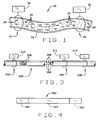
- a system 20 for communicating data between two points in accordance with this invention is shown schematically in Fig. 1.
- the system 20 comprises a fluid flow 22, which may be a flow through a conduit, pipe, or duct, or a flow that is unrestrained.
- the system is adapted to permit communication between two points 24 and 26 along the fluid flow 22.
- the system includes a plurality of data carriers 28.
- the data carriers 28 are data storage devices that can be remotely written to and read.
- the data carriers 28 preferably comprise a circuit including a data chip and an antenna encapsulated to protect circuit from the fluid flow 22.
- the data carriers 28 preferably have the size, weight, and shape to flow smoothly in the fluid flow 22.
- Suitable data carriers could be similar in construction to commercially available noncontact identification transponders, for example the AVID identity tags or AVID industrial RF ID transponders available from Avid, 3179 Hamner Avenue, Norco, California 91760. These identity tags and transponders comprise an integrated circuit and coil capacitor hermetically sealed in biocompatible glass.
- the AVID2023 identify tag is only 0.45 in x 0.08 in (12 mm x 2.1 mm), weighs 0.0021 oz. (0.06 gm), and can carry 96 bits.
- the tag has no internal power source, and is instead powered by RF energy from the reader, which generates a 125KHz radio signal.
- the tag When the tag is within the electromagnetic field of the reader, the tag transmits its encoded data to the reader, where it can be decoded and stored.
- Typical read distances range from 4.125 inches (10cm) to about 10.25 inches (26 cm), and read times are less than 40 msec.
- the system 20 also includes a remote writing device 30 at the first point 24 for remotely writing to the data carriers 28, and a remote reading device 32 at the second point 26 for remotely reading the data carriers 28 as they pass the second point in the stream 22.
- the data written on the data carriers 28 preferably includes ordering or sequencing data as well as information data, so that the information data can be properly reassembled. Because spacing between the data carriers 28 can vary, and in fact the data carriers can arrive at the second point out of sequence, the ordering or sequencing information allows the data to be reassembled correctly.
- the data is preferably redundantly written on at least two data carriers 28, to reduce the risk of lost data if some data carriers 28 become lost or damaged.
- FIG. 2 is a schematic view of a drilling rig incorporating the communications system of the present invention.
- the drilling rig includes a derrick 100 with a drilling string 102 extending to the drilling tool assembly 104 down the wellbore W.
- the drilling tool assembly includes a drill bit 106 and instrumentation 108, which can include inertial navigation position sensors, sensors for detecting the type and condition of the rock, and even cameras.
- the wellbore W may be partially encased by a casing C.
- Drilling mud or fluid is circulated down the drilling string 102 and returns in the wellbore in the space surrounding the drilling string 102.
- the drilling fluid serves to help clear debris from the drill bit, lubricate the drill bit, cool the drilling assembly, and contain downhole pressure against "blowouts".
- a plurality of data carriers 110 are circulated in the drilling fluid.
- the data carriers are preferably constructed as described above with respect to data carriers 28. The inventor believes that a generally spherical configuration with a diameter of less than 0.5 inch (1.25 cm) is preferred.
- the drilling assembly 104 includes a filter 112 for trapping the data carriers 110 that flow down through the drilling string 102, to prevent the data carriers from being carried by the drilling fluid to the drill bit 106, where the data carriers could be destroyed.
- the drilling assembly also includes a data writer 114 for remotely writing to the data carriers that flow in the drilling fluid down the drilling string 102 to the drilling assembly 104.
- the data writer 114 can, for example, write data accumulated by the sensors 108 to the data carriers 110.
- the process of writing data may clear the memory of the data carrier, or a separate eraser 116 can be provided to clear previously recorded data.
- the data carriers 110 then flow with the drilling fluid back up the wellbore in the space surrounding the drilling string 102. At the top of the well the drilling fluid is drawn off in a conduit 118.
- a data reader 120 can be provided to read the data from the data carriers 110, and a data eraser 122 can be provided to erase the data carriers as they flow in the drilling fluid through the conduit 118.
- a separator or shaker table 124 can collect the data carriers 110 from the drilling fluid (and separate them from the rock chips carried in the drilling fluid) for reuse.
- the drilling rig 100 is preferably configured for two way communication so that in addition to permitting information about the underground conditions to be communicated to the surface, instructions from the surface can be communicated to the drilling tool assembly 104.
- a data writer 126 can be provided at the top of the well W for writing data to data carriers 110 either before the carriers are introduced into the drilling fluid or after the data carriers are introduced into the drilling fluid.
- the drilling assembly 104 is then also provided with a data reader 128 to read the data on the data carriers 110 as they reach the drilling tool assembly 104 in the drilling string 102.
- Data collected by the sensors 108 in the drilling assembly 104 can be written to the data carriers 110 by the data writer 114.
- the data is preferably written redundantly to a plurality of carriers, so that if some of the carriers are lost or destroyed, data is not lost.
- redundantly writing data or in addition to redundantly writing data, where two way communication is provided, data can simply be stored until confirmation is received that data was received at the other point, and if confirmation is not received within a certain period of time, the data can be retransmitted.
- the drilling assembly can store data collected about the drilling activity and periodically resend the information until confirmation is recorded that the data has been received.
- instructions to the drilling assembly can be written by data writer 126 before the data carriers 110 travel down the drilling string 102 to the drilling tool assembly 104.
- the drilling tool assembly 104 can read the instructions and respond.
- the drilling assembly can write to the data carriers before they return to the surface.
- This data can include confirmation of the receipt and/or execution of the instructions.
- the data is also preferably written with ordering information to facilitate its reassembly in the proper order.
- the data carriers can travel from the surface to the drilling head in as little as a few minutes.
- data transfer rates can easily be increased tenfold over current technology. For example, in a drilling rig with a drilling string having an internal diameter of 2 inches, if drilling fluid is circulated at a rate of a few hundred gallons per minute, the total travel time to the bottom of a 10,000 foot well would be less than about ten minutes. Total travel time from the bottom of the well back to the top might be slightly longer, because the cross sectional area of the space outside the drilling string is generally greater than the interior of the drilling string.
- a pipeline constructed according to the principles of this invention is indicated generally as 200 in Fig. 3.
- the pipeline 200 is adapted to conduct a fluid flow between a point 202 first and second and third points 204 and 206, respectively.
- a plurality of data carriers 208 are introduced into the flow in the pipeline.
- a data writer 210 can write data to the data carriers.
- This data can include data about the fluid passing in the pipe.
- the data carriers 208 can carry information about the grade and type of product being transported, or the ownership of the product.
- the data written on the carriers passing in the fluid can be read by one or more data readers 212 at the second point 204 or the third point 206 or elsewhere along the pipeline.
- a sample data structure 300 for the data carriers is shown in Fig. 4.
- the data preferably includes ordering information 302, data 304, and error checking data 305.
- a plurality of data carriers 110 are introduced into the drilling fluid or mud as it is enters the drilling string 102.
- the data carriers pass through the drilling string 102 where they are trapped by the filter 112, and are diverted to the outside of the drill string where they begin their return to the surface.
- the data carriers 110 pass the eraser 116 and the data writer 114, where data accumulated from the sensors 108 is written to the data carriers.
- the carriers then pass in the space in the well outside of drilling string 102, and out the conduit 118.
- the data carriers move in the conduit 118 past the data reader 120 where the data written to the data carriers is read.
- the data carriers move in the conduct 118 past the data eraser 122 where the data written to the data carriers is erased. This provides security and ensures that the data carriers are ready to be reused.
- the data carriers are recovered in the shaker table which simultaneously separates the data carriers from the drilling fluid and from the rock chips resulting from the drilling.
- the data carriers 110 can be reintroduced into the drilling fluid and introduced into the well, and pass the data writer 126 where data, for example instructions for the drilling tool assembly, is written to the carriers.
- the data carriers 110 travel down the drilling string 102 to the data reader 128 where the data is read and can be processed by the drilling tool assembly.
- a plurality of data carriers 208 are introduced into the flow, and as the data carriers pass the first point 202, the data writer 210 writes data to the data carriers, for example data about the identity of the fluid in the flow, or the ownership or destination of the fluid in the flow.
- the data carriers 208 pass points 204 and 206, the data readers read the data so that it can be processed and used locally.
- the apparatus and method of the present invention permit data to be communicated in a preexisting fluid path, or a fluid path created specifically for purposes of communication.
- the communication is secure and reliable, and the apparatus and method permit communication even where conventional methods of communication are unsatisfactory.
Landscapes
- Engineering & Computer Science (AREA)
- Life Sciences & Earth Sciences (AREA)
- Mining & Mineral Resources (AREA)
- Geology (AREA)
- Physics & Mathematics (AREA)
- Fluid Mechanics (AREA)
- Geophysics (AREA)
- Environmental & Geological Engineering (AREA)
- Remote Sensing (AREA)
- Signal Processing (AREA)
- Computer Networks & Wireless Communication (AREA)
- General Life Sciences & Earth Sciences (AREA)
- Geochemistry & Mineralogy (AREA)
- Arrangements For Transmission Of Measured Signals (AREA)
- Earth Drilling (AREA)
- Selective Calling Equipment (AREA)
Applications Claiming Priority (2)
| Application Number | Priority Date | Filing Date | Title |
|---|---|---|---|
| US764668 | 1996-12-11 | ||
| US08/764,668 US5991602A (en) | 1996-12-11 | 1996-12-11 | Method of and system for communication between points along a fluid flow |
Publications (2)
| Publication Number | Publication Date |
|---|---|
| EP0848512A2 true EP0848512A2 (fr) | 1998-06-17 |
| EP0848512A3 EP0848512A3 (fr) | 2000-05-24 |
Family
ID=25071398
Family Applications (1)
| Application Number | Title | Priority Date | Filing Date |
|---|---|---|---|
| EP97309696A Withdrawn EP0848512A3 (fr) | 1996-12-11 | 1997-12-02 | Méthode pour et système de communication entre des points le long de l'écoulement d'un fluide |
Country Status (8)
| Country | Link |
|---|---|
| US (1) | US5991602A (fr) |
| EP (1) | EP0848512A3 (fr) |
| JP (1) | JPH10231679A (fr) |
| CA (1) | CA2224464A1 (fr) |
| NO (1) | NO975225L (fr) |
| RU (1) | RU97120891A (fr) |
| SG (1) | SG65031A1 (fr) |
| TW (1) | TW362309B (fr) |
Cited By (8)
| Publication number | Priority date | Publication date | Assignee | Title |
|---|---|---|---|---|
| GB2391565A (en) * | 2002-07-30 | 2004-02-11 | Schlumberger Holdings | Telemetry system using data carrying elements |
| GB2432862A (en) * | 2003-06-18 | 2007-06-06 | Weatherford Lamb | Method for actuating a downhole tool |
| EP1212515B1 (fr) * | 1999-09-07 | 2010-09-22 | Halliburton Energy Services, Inc. | Procedes et appareil associe de recuperation de donnees, de surveillance et de commande d'outils au fond d'un puits |
| WO2014187346A1 (fr) * | 2013-05-22 | 2014-11-27 | 中国石油化工股份有限公司 | Système de transmission de données et procédé de transmission au sol de données de mesure de fond en cours de forage |
| CN104179495A (zh) * | 2013-05-22 | 2014-12-03 | 中国石油化工股份有限公司 | 一种随钻地面与井下数据交互方法及系统 |
| CN105089644A (zh) * | 2014-05-22 | 2015-11-25 | 中国石油化工股份有限公司 | 传输随钻井下测量数据至地面的数据传输系统及方法 |
| CN107420093A (zh) * | 2016-03-10 | 2017-12-01 | 中国石油化工股份有限公司 | 随钻测量方法及系统 |
| US11118446B2 (en) | 2014-06-13 | 2021-09-14 | Baker Hughes Oilfield Operations Llc | System and method for drilling fluid parameters detection |
Families Citing this family (56)
| Publication number | Priority date | Publication date | Assignee | Title |
|---|---|---|---|---|
| US6333699B1 (en) * | 1998-08-28 | 2001-12-25 | Marathon Oil Company | Method and apparatus for determining position in a pipe |
| US20040239521A1 (en) * | 2001-12-21 | 2004-12-02 | Zierolf Joseph A. | Method and apparatus for determining position in a pipe |
| US7283061B1 (en) * | 1998-08-28 | 2007-10-16 | Marathon Oil Company | Method and system for performing operations and for improving production in wells |
| AU5651699A (en) * | 1998-09-18 | 2000-04-10 | Hitachi Maxell, Ltd. | Noncontact communication semiconductor device |
| US6935425B2 (en) * | 1999-05-28 | 2005-08-30 | Baker Hughes Incorporated | Method for utilizing microflowable devices for pipeline inspections |
| US6989764B2 (en) * | 2000-03-28 | 2006-01-24 | Schlumberger Technology Corporation | Apparatus and method for downhole well equipment and process management, identification, and actuation |
| US7014100B2 (en) * | 2001-04-27 | 2006-03-21 | Marathon Oil Company | Process and assembly for identifying and tracking assets |
| TW561722B (en) * | 2002-03-26 | 2003-11-11 | Culture Com Technology Macao L | System and method for communication via medium |
| US20040257241A1 (en) * | 2002-05-10 | 2004-12-23 | Menger Stefan K. | Method and apparatus for transporting data |
| US20040207539A1 (en) * | 2002-10-22 | 2004-10-21 | Schultz Roger L | Self-contained downhole sensor and method of placing and interrogating same |
| GB2396170B (en) * | 2002-12-14 | 2007-06-06 | Schlumberger Holdings | System and method for wellbore communication |
| US7528736B2 (en) * | 2003-05-06 | 2009-05-05 | Intelliserv International Holding | Loaded transducer for downhole drilling components |
| US6898529B2 (en) * | 2003-09-05 | 2005-05-24 | Halliburton Energy Services, Inc. | Method and system for determining parameters inside a subterranean formation using data sensors and a wireless ad hoc network |
| US7442932B2 (en) * | 2003-11-18 | 2008-10-28 | Halliburton Energy Services, Inc. | High temperature imaging device |
| EP3249154A1 (fr) * | 2003-11-18 | 2017-11-29 | Halliburton Energy Services Inc. | Système d'outil d'un environnement à haute température et procédé |
| US20050104104A1 (en) * | 2003-11-18 | 2005-05-19 | Halliburton Energy Services, Inc. | High temperature memory device |
| US7486688B2 (en) * | 2004-03-29 | 2009-02-03 | Conexant Systems, Inc. | Compact packet switching node storage architecture employing Double Data Rate Synchronous Dynamic RAM |
| GB0425008D0 (en) * | 2004-11-12 | 2004-12-15 | Petrowell Ltd | Method and apparatus |
| US7293715B2 (en) * | 2004-12-16 | 2007-11-13 | Schlumberger Technology Corporation | Marking system and method |
| US7296462B2 (en) * | 2005-05-03 | 2007-11-20 | Halliburton Energy Services, Inc. | Multi-purpose downhole tool |
| US8826972B2 (en) * | 2005-07-28 | 2014-09-09 | Intelliserv, Llc | Platform for electrically coupling a component to a downhole transmission line |
| US20070023185A1 (en) * | 2005-07-28 | 2007-02-01 | Hall David R | Downhole Tool with Integrated Circuit |
| FR2891637B1 (fr) * | 2005-09-30 | 2008-01-25 | Airbus France Sas | Dispositif et procede pour le controle d'un equipement |
| US9200500B2 (en) | 2007-04-02 | 2015-12-01 | Halliburton Energy Services, Inc. | Use of sensors coated with elastomer for subterranean operations |
| US8297352B2 (en) * | 2007-04-02 | 2012-10-30 | Halliburton Energy Services, Inc. | Use of micro-electro-mechanical systems (MEMS) in well treatments |
| US8342242B2 (en) * | 2007-04-02 | 2013-01-01 | Halliburton Energy Services, Inc. | Use of micro-electro-mechanical systems MEMS in well treatments |
| US9822631B2 (en) | 2007-04-02 | 2017-11-21 | Halliburton Energy Services, Inc. | Monitoring downhole parameters using MEMS |
| US8316936B2 (en) * | 2007-04-02 | 2012-11-27 | Halliburton Energy Services Inc. | Use of micro-electro-mechanical systems (MEMS) in well treatments |
| US8291975B2 (en) * | 2007-04-02 | 2012-10-23 | Halliburton Energy Services Inc. | Use of micro-electro-mechanical systems (MEMS) in well treatments |
| US9879519B2 (en) | 2007-04-02 | 2018-01-30 | Halliburton Energy Services, Inc. | Methods and apparatus for evaluating downhole conditions through fluid sensing |
| US8162050B2 (en) * | 2007-04-02 | 2012-04-24 | Halliburton Energy Services Inc. | Use of micro-electro-mechanical systems (MEMS) in well treatments |
| US9732584B2 (en) * | 2007-04-02 | 2017-08-15 | Halliburton Energy Services, Inc. | Use of micro-electro-mechanical systems (MEMS) in well treatments |
| US8297353B2 (en) * | 2007-04-02 | 2012-10-30 | Halliburton Energy Services, Inc. | Use of micro-electro-mechanical systems (MEMS) in well treatments |
| US20110187556A1 (en) * | 2007-04-02 | 2011-08-04 | Halliburton Energy Services, Inc. | Use of Micro-Electro-Mechanical Systems (MEMS) in Well Treatments |
| US8302686B2 (en) * | 2007-04-02 | 2012-11-06 | Halliburton Energy Services Inc. | Use of micro-electro-mechanical systems (MEMS) in well treatments |
| US9494032B2 (en) | 2007-04-02 | 2016-11-15 | Halliburton Energy Services, Inc. | Methods and apparatus for evaluating downhole conditions with RFID MEMS sensors |
| US10358914B2 (en) | 2007-04-02 | 2019-07-23 | Halliburton Energy Services, Inc. | Methods and systems for detecting RFID tags in a borehole environment |
| US7712527B2 (en) * | 2007-04-02 | 2010-05-11 | Halliburton Energy Services, Inc. | Use of micro-electro-mechanical systems (MEMS) in well treatments |
| US9194207B2 (en) | 2007-04-02 | 2015-11-24 | Halliburton Energy Services, Inc. | Surface wellbore operating equipment utilizing MEMS sensors |
| US10262168B2 (en) | 2007-05-09 | 2019-04-16 | Weatherford Technology Holdings, Llc | Antenna for use in a downhole tubular |
| GB0720421D0 (en) | 2007-10-19 | 2007-11-28 | Petrowell Ltd | Method and apparatus for completing a well |
| GB0804306D0 (en) | 2008-03-07 | 2008-04-16 | Petrowell Ltd | Device |
| US9194227B2 (en) | 2008-03-07 | 2015-11-24 | Marathon Oil Company | Systems, assemblies and processes for controlling tools in a wellbore |
| US10119377B2 (en) * | 2008-03-07 | 2018-11-06 | Weatherford Technology Holdings, Llc | Systems, assemblies and processes for controlling tools in a well bore |
| US20090251960A1 (en) * | 2008-04-07 | 2009-10-08 | Halliburton Energy Services, Inc. | High temperature memory device |
| US8434354B2 (en) * | 2009-03-06 | 2013-05-07 | Bp Corporation North America Inc. | Apparatus and method for a wireless sensor to monitor barrier system integrity |
| GB0914650D0 (en) * | 2009-08-21 | 2009-09-30 | Petrowell Ltd | Apparatus and method |
| US20110253373A1 (en) * | 2010-04-12 | 2011-10-20 | Baker Hughes Incorporated | Transport and analysis device for use in a borehole |
| US8850899B2 (en) | 2010-04-15 | 2014-10-07 | Marathon Oil Company | Production logging processes and systems |
| EP3677748B1 (fr) * | 2010-04-27 | 2024-05-29 | National Oilwell Varco, L.P. | Système et méthode pour la détermination de la durée d'utilisation de tiges de forage |
| GB2496913B (en) | 2011-11-28 | 2018-02-21 | Weatherford Uk Ltd | Torque limiting device |
| US9250339B2 (en) * | 2012-03-27 | 2016-02-02 | Baker Hughes Incorporated | System and method to transport data from a downhole tool to the surface |
| CA2918014C (fr) * | 2013-08-28 | 2019-01-08 | Halliburton Energy Services, Inc. | Systeme de suivi et d'echantillonnage de coupes de puits de forage a l'aide d'etiquettes rfid |
| GB2535035B (en) * | 2013-09-05 | 2017-04-05 | Shell Int Research | Method and system for monitoring fluid flux in a well |
| WO2020232521A1 (fr) * | 2019-05-19 | 2020-11-26 | Ouro Negro Tecnologias Em Equipamentos Industriais S/A | Système de surveillance permanente des paramètres fonctionnels de puits de pétrole et de gaz naturel |
| US11827249B2 (en) * | 2021-12-01 | 2023-11-28 | Cooley Enterprises, LLC | Clean energy integrated transportation system using a hydro system |
Family Cites Families (7)
| Publication number | Priority date | Publication date | Assignee | Title |
|---|---|---|---|---|
| US4000927A (en) * | 1975-06-26 | 1977-01-04 | Hitachi, Ltd. | Capsule hydraulic-transportation system |
| US4578675A (en) * | 1982-09-30 | 1986-03-25 | Macleod Laboratories, Inc. | Apparatus and method for logging wells while drilling |
| US4724434A (en) * | 1984-05-01 | 1988-02-09 | Comdisco Resources, Inc. | Method and apparatus using casing for combined transmission of data up a well and fluid flow in a geological formation in the well |
| DE4319878A1 (de) * | 1992-06-17 | 1993-12-23 | Micron Technology Inc | Hochfrequenz-Identifikationseinrichtung (HFID) und Verfahren zu ihrer Herstellung |
| JPH06132907A (ja) * | 1992-10-20 | 1994-05-13 | Nippon Telegr & Teleph Corp <Ntt> | 管路内信号伝送方法及び装置 |
| US5485148A (en) * | 1993-03-31 | 1996-01-16 | Tseng; Ling-Yuan | Pipeline fluid travel monitoring system |
| US5675251A (en) * | 1994-07-07 | 1997-10-07 | Hydroscope Inc. | Device and method for inspection of pipelines |
-
1996
- 1996-12-11 US US08/764,668 patent/US5991602A/en not_active Expired - Fee Related
-
1997
- 1997-11-13 NO NO975225A patent/NO975225L/no not_active Application Discontinuation
- 1997-11-18 SG SG1997004077A patent/SG65031A1/en unknown
- 1997-11-25 TW TW086117623A patent/TW362309B/zh active
- 1997-12-02 EP EP97309696A patent/EP0848512A3/fr not_active Withdrawn
- 1997-12-05 JP JP9335204A patent/JPH10231679A/ja not_active Withdrawn
- 1997-12-10 RU RU97120891/09A patent/RU97120891A/ru not_active Application Discontinuation
- 1997-12-11 CA CA002224464A patent/CA2224464A1/fr not_active Abandoned
Cited By (25)
| Publication number | Priority date | Publication date | Assignee | Title |
|---|---|---|---|---|
| EP1212515B1 (fr) * | 1999-09-07 | 2010-09-22 | Halliburton Energy Services, Inc. | Procedes et appareil associe de recuperation de donnees, de surveillance et de commande d'outils au fond d'un puits |
| AU2003227338B2 (en) * | 2002-07-30 | 2008-10-02 | Schlumberger Technology B.V. | Universal downhole tool control apparatus and methods |
| US6915848B2 (en) | 2002-07-30 | 2005-07-12 | Schlumberger Technology Corporation | Universal downhole tool control apparatus and methods |
| GB2391565B (en) * | 2002-07-30 | 2006-01-11 | Schlumberger Holdings | Downhole tool control apparatus and methods |
| AU2003227338C1 (en) * | 2002-07-30 | 2009-03-05 | Schlumberger Technology B.V. | Universal downhole tool control apparatus and methods |
| AU2008207382B2 (en) * | 2002-07-30 | 2009-01-08 | Schlumberger Technology B.V. | Universal downhole tool control apparatus and methods |
| GB2391565A (en) * | 2002-07-30 | 2004-02-11 | Schlumberger Holdings | Telemetry system using data carrying elements |
| GB2402954B (en) * | 2003-06-18 | 2007-11-21 | Weatherford Lamb | Methods and apparatus for actuating a downhole tool |
| GB2439234A (en) * | 2003-06-18 | 2007-12-19 | Weatherford Lamb | Centraliser actuated using downhole sensor to relay signal from surface |
| GB2432862B (en) * | 2003-06-18 | 2008-03-12 | Weatherford Lamb | Method for actuating a downhole tool |
| GB2439234B (en) * | 2003-06-18 | 2008-04-16 | Weatherford Lamb | Methods for actuating a downhole tool |
| GB2436492B (en) * | 2003-06-18 | 2007-11-21 | Weatherford Lamb | Methods and apparatus for actuating a downhole tool |
| GB2436492A (en) * | 2003-06-18 | 2007-09-26 | Weatherford Lamb | Tool actuator with radio frequency tag reader |
| US7252152B2 (en) | 2003-06-18 | 2007-08-07 | Weatherford/Lamb, Inc. | Methods and apparatus for actuating a downhole tool |
| US7503398B2 (en) | 2003-06-18 | 2009-03-17 | Weatherford/Lamb, Inc. | Methods and apparatus for actuating a downhole tool |
| GB2432862A (en) * | 2003-06-18 | 2007-06-06 | Weatherford Lamb | Method for actuating a downhole tool |
| WO2014187346A1 (fr) * | 2013-05-22 | 2014-11-27 | 中国石油化工股份有限公司 | Système de transmission de données et procédé de transmission au sol de données de mesure de fond en cours de forage |
| CN104179495A (zh) * | 2013-05-22 | 2014-12-03 | 中国石油化工股份有限公司 | 一种随钻地面与井下数据交互方法及系统 |
| GB2533044A (en) * | 2013-05-22 | 2016-06-08 | China Petroleum & Chem Corp | Data transmission system and method for transmitting downhole measurement-while-drilling data to ground |
| US9739141B2 (en) | 2013-05-22 | 2017-08-22 | China Petroleum & Chemical Corporation | Data transmission system and method for transmission of downhole measurement-while-drilling data to ground |
| GB2533044B (en) * | 2013-05-22 | 2017-12-13 | China Petroleum & Chem Corp | Data transmission system and method for transmission of downhole measurement-while-drilling data to ground |
| CN105089644A (zh) * | 2014-05-22 | 2015-11-25 | 中国石油化工股份有限公司 | 传输随钻井下测量数据至地面的数据传输系统及方法 |
| CN105089644B (zh) * | 2014-05-22 | 2019-01-01 | 中国石油化工股份有限公司 | 传输随钻井下测量数据至地面的数据传输系统及方法 |
| US11118446B2 (en) | 2014-06-13 | 2021-09-14 | Baker Hughes Oilfield Operations Llc | System and method for drilling fluid parameters detection |
| CN107420093A (zh) * | 2016-03-10 | 2017-12-01 | 中国石油化工股份有限公司 | 随钻测量方法及系统 |
Also Published As
| Publication number | Publication date |
|---|---|
| EP0848512A3 (fr) | 2000-05-24 |
| JPH10231679A (ja) | 1998-09-02 |
| MX9710033A (es) | 1998-09-30 |
| RU97120891A (ru) | 1999-10-27 |
| NO975225L (no) | 1998-06-12 |
| CA2224464A1 (fr) | 1998-06-11 |
| SG65031A1 (en) | 1999-05-25 |
| US5991602A (en) | 1999-11-23 |
| NO975225D0 (no) | 1997-11-13 |
| TW362309B (en) | 1999-06-21 |
Similar Documents
| Publication | Publication Date | Title |
|---|---|---|
| US5991602A (en) | Method of and system for communication between points along a fluid flow | |
| US20040257241A1 (en) | Method and apparatus for transporting data | |
| US9250339B2 (en) | System and method to transport data from a downhole tool to the surface | |
| US6993432B2 (en) | System and method for wellbore communication | |
| US7293715B2 (en) | Marking system and method | |
| CA2444657C (fr) | Dispositif et methodes de transport d'instruments dans un puits de forage par tige de pompage en continu | |
| US8016036B2 (en) | Tagging a formation for use in wellbore related operations | |
| EP1188265B1 (fr) | Procede et dispositif de determination de position dans un conduit | |
| US9140818B2 (en) | Method and apparatus for determining position in a pipe | |
| US8681000B2 (en) | Low frequency inductive tagging for lifecycle management | |
| CA2431288C (fr) | Procede de placement d'outils de fond dans un puits de forage | |
| AU649071B2 (en) | Transmission of data in boreholes | |
| EP0927812B1 (fr) | Répéteur de signal électromagnétique | |
| US20110191028A1 (en) | Measurement devices with memory tags and methods thereof | |
| AU2015381874B2 (en) | Fluid monitoring using radio frequency identification | |
| WO2005091900A3 (fr) | Dispositifs et procedes de marquage de puits de forage | |
| CN105089644A (zh) | 传输随钻井下测量数据至地面的数据传输系统及方法 | |
| WO2001042622A1 (fr) | Procede et dispositif de transfert de donnees | |
| MX2015001315A (es) | Deflector activado a distancia. | |
| US20200240263A1 (en) | Ruggedized buoyant memory modules for data logging and delivery system using fluid flow in oil and gas wells | |
| US20180010446A1 (en) | Repeater for a wellbore | |
| CN107420093A (zh) | 随钻测量方法及系统 | |
| US20140333452A1 (en) | Inter-Tool Communication Flow Control in Toolbus System of Cable Telemetry | |
| MXPA97010033A (en) | Method and system for communication between points alo long of a flow of flu | |
| CN107152273A (zh) | 一种钻井采集参数ic浮子传递读取系统 |
Legal Events
| Date | Code | Title | Description |
|---|---|---|---|
| PUAI | Public reference made under article 153(3) epc to a published international application that has entered the european phase |
Free format text: ORIGINAL CODE: 0009012 |
|
| AK | Designated contracting states |
Kind code of ref document: A2 Designated state(s): AT BE CH DE DK ES FI FR GB GR IE IT LI LU MC NL PT SE |
|
| AX | Request for extension of the european patent |
Free format text: AL;LT;LV;MK;RO;SI |
|
| PUAL | Search report despatched |
Free format text: ORIGINAL CODE: 0009013 |
|
| AK | Designated contracting states |
Kind code of ref document: A3 Designated state(s): AT BE CH DE DK ES FI FR GB GR IE IT LI LU MC NL PT SE |
|
| AX | Request for extension of the european patent |
Free format text: AL;LT;LV;MK;RO;SI |
|
| AKX | Designation fees paid | ||
| REG | Reference to a national code |
Ref country code: DE Ref legal event code: 8566 |
|
| STAA | Information on the status of an ep patent application or granted ep patent |
Free format text: STATUS: THE APPLICATION IS DEEMED TO BE WITHDRAWN |
|
| 18D | Application deemed to be withdrawn |
Effective date: 20001128 |