EP0849072A2 - Beutelherstellungsapparat mit automatisches Positionssystem von Anschlusselementen - Google Patents
Beutelherstellungsapparat mit automatisches Positionssystem von Anschlusselementen Download PDFInfo
- Publication number
- EP0849072A2 EP0849072A2 EP97203792A EP97203792A EP0849072A2 EP 0849072 A2 EP0849072 A2 EP 0849072A2 EP 97203792 A EP97203792 A EP 97203792A EP 97203792 A EP97203792 A EP 97203792A EP 0849072 A2 EP0849072 A2 EP 0849072A2
- Authority
- EP
- European Patent Office
- Prior art keywords
- bag
- attachments
- web
- attachment
- making apparatus
- Prior art date
- Legal status (The legal status is an assumption and is not a legal conclusion. Google has not performed a legal analysis and makes no representation as to the accuracy of the status listed.)
- Granted
Links
Images

Classifications
-
- B—PERFORMING OPERATIONS; TRANSPORTING
- B31—MAKING ARTICLES OF PAPER, CARDBOARD OR MATERIAL WORKED IN A MANNER ANALOGOUS TO PAPER; WORKING PAPER, CARDBOARD OR MATERIAL WORKED IN A MANNER ANALOGOUS TO PAPER
- B31B—MAKING CONTAINERS OF PAPER, CARDBOARD OR MATERIAL WORKED IN A MANNER ANALOGOUS TO PAPER
- B31B70/00—Making flexible containers, e.g. envelopes or bags
-
- B—PERFORMING OPERATIONS; TRANSPORTING
- B31—MAKING ARTICLES OF PAPER, CARDBOARD OR MATERIAL WORKED IN A MANNER ANALOGOUS TO PAPER; WORKING PAPER, CARDBOARD OR MATERIAL WORKED IN A MANNER ANALOGOUS TO PAPER
- B31B—MAKING CONTAINERS OF PAPER, CARDBOARD OR MATERIAL WORKED IN A MANNER ANALOGOUS TO PAPER
- B31B70/00—Making flexible containers, e.g. envelopes or bags
- B31B70/006—Controlling; Regulating; Measuring; Safety measures
-
- B—PERFORMING OPERATIONS; TRANSPORTING
- B31—MAKING ARTICLES OF PAPER, CARDBOARD OR MATERIAL WORKED IN A MANNER ANALOGOUS TO PAPER; WORKING PAPER, CARDBOARD OR MATERIAL WORKED IN A MANNER ANALOGOUS TO PAPER
- B31B—MAKING CONTAINERS OF PAPER, CARDBOARD OR MATERIAL WORKED IN A MANNER ANALOGOUS TO PAPER
- B31B2160/00—Shape of flexible containers
- B31B2160/10—Shape of flexible containers rectangular and flat, i.e. without structural provision for thickness of contents
Definitions
- the present invention relates generally to a bag-making machine which handles a web of film material from which bags are made in end-to-end relationship, and more particularly to a bag-making apparatus having a plurality of movably positionable attachments thereon, with an arrangement provided for automatically proportionately positioning the attachments relative to each other for high-speed manufacture of bags.
- a substantially continuous web of film material such as plastic or paper
- the bag-making machines of this type may be configured for intermittent operation, that is, for intermittent advancement of the web of film material as it is converted to a series of bags.
- intermittent bag-making machines i.e., wicketers, flat belt, bottom seal machine, etc.
- various attachments of the machine such as those for effecting wicket punching, handle cutout, etc., be positioned proportionately to each other in connection with altering the machine to accommodate a change in the print repeat length, as may result from tension changes in the attachment bed area of the machine or from variations in the printing process and the subsequent rewinding of the film web.
- a photoeye of the machine tracks the registration (print) mark provided on each of the bags being made.
- draw length is adjusted in such a way that the registration mark stays in registry with the photoeye. Because the various bag-making processes are referenced with respect to this photoeye, the photoeye is sometimes considered to be the only "fixed" point of the process, that is, fixed in relation to the registration mark (but not necessarily fixed in relation to the attachment rail of the apparatus).
- One such auto-correction arrangement for bag-making attachments entailing use of a "combined mount” has included a motor-driven gear thereon.
- the gear is in meshing engagement with a gear rack which extends along an attachment bed of the machine, whereby operation of the motor effects upstream and downstream movement of the combined mount.
- two photoeyes are mounted on one of the attachments, with the photoeyes offset (such as by 3 mm.) in the direction of the film web. Signals from these photoeyes are directed to a programmable logic controller, which in turn operates the adjusting motor.
- the "combined mount” and the photoeyes are positioned in such a way that in normal running conditions one photoeye is on the registration mark, and the other photoeye is next to the registration mark.
- the auto-correction system is armed or activated. Depending upon the relative positioning of the mount, and the relationship of the photoeyes to the registration mark, the auto-correction system will either move the mount upstream or downstream, or effect no movement. While this arrangement facilitates automatic correction of the attachments, this arrangement has the disadvantages of having a 3 mm. dead gap (wherein no proportional adjustment is effected), and still suffers from the deficiency that only one of the attachments is exactly correctly positioned. The other attachments on the "combined mount" will have an error proportional to their distance from the exactly correctly positioned one of the attachments.
- a three-roller vertical S-wrap is positioned on the attachment bed of the bag-making machine.
- this three-roll arrangement can be mounted immediately upstream from the so-called centerfold gusset former.
- the middle S-wrap roller can move up and down by means of an electric motor.
- the auto-correction arrangement includes an analog photoeye mounted on the machine frame or attachment rail upstream of the S-wrap rollers. The signal from this photoeye is fed into a guiding system, which drives the motor on the middle S-wrap roller. During web stop (again, during sealing and for a time period before and after), the auto-correction system is activated.
- the S-wrap roller is positioned in such a way that in normal running conditions, the photoeye is on one edge of the registration mark. Depending upon the signal generated by the photoeye, the S-wrap roller is moved up or down, to accumulate or release web material, until the photoeye mark is back on the edge of the registration mark.
- this system suffers from the disadvantage that only one attachment is exactly correctly positioned, while other attachments of the bag-making machine will be positioned with an error which is proportional to their distance from the exactly correctly positioned attachment.
- a "combined mount” having a plurality of attachments thereon is movably positioned on the attachment bed of the machine.
- a motor-driven gear is provided on the combined mount, with the gear in meshing engagement with a gear rack extending along the attachment bed. Operation of the motor effects movement of the combined mount upstream or downstream of the attachment bed.
- an analog photoeye is mounted on one of the attachments of the mount. The signal of this photoeye is fed into a guiding system, which drives the motor on the combined mount.
- the combined mount (and the photoeye thereon) are positioned in such a way that in normal running conditions, the photoeye is on one edge of the registration mark.
- the auto-correction system is activated.
- the auto-correction arrangement will move the combined mount upstream, downstream, or not at all. As in previously-described systems, this arrangement results only in one of the attachments on the mount being exactly correctly positioned. Again, other attachments on the combined mount will be positioned with an error proportional to their distance from the exactly correctly positioned attachment.
- the present invention is directed to a bag-making apparatus having an automated adjustment system for effecting correct relative positioning of bag-making attachments to facilitate correct positioning of various attachments attendant to changes in the print repeat length, thus facilitating accurate high-speed operation while achieving smaller variations in the resultant bags.
- a bag-making apparatus embodying the principles of the present invention is illustrated as an intermittent bag-making machine which can be configured for various types of sealing (i.e., bottom seal, mixed seal, side weld, etc.), and can be configured to permit bags to be "picked off” by any of various known techniques (i.e., wicket, on-the-roll, needle stacking, flat belt stacking, etc.).
- the apparatus includes an attachment bed which defines a web flow path along which a web of bag-making material is moved.
- a web draw drive mechanism is provided for drawing the web of bag-making material along the attachment bed.
- the apparatus includes a plurality of bag-making attachments which are movably mounted on the attachment bed along the web flow path.
- the present apparatus includes an auto-correction arrangement by which the various attachments of the machine are proportionately positioned relative to each other as they are automatically positioned along the web flow path of the apparatus. This provides desirably accurate relative positioning of the attachments, thus facilitating high-speed operation of the machine, while accommodating print repeat length changes resulting from tension changes, or printing variations. While it is contemplated that such adjustment be effected during the stop or dwell period of the web it is within the purview of the present invention to effect adjustment during drawing of the web following measurement of the error during the web stops or dwell prior to drawing of the web.
- the apparatus includes an automated adjustment arrangement for adjustably positioning a plurality of bag-making attachments along the attachment bed of the apparatus.
- the adjustment arrangement is configured to effect conjoint, translational movement of the attachments on the attachment bed along the web flow path while positioning the attachments proportionately to each other.
- the adjustment arrangement may be provided in the form of servo drive motors or the like respectively mounted on the attachments of the apparatus
- the illustrated embodiment includes a desirably straightforward drive mechanism for effecting conjoint translational movement of the attachments. It is to be understood, however, that it is within the purview of the present invention to provide an arrangement for effecting proportional relative positioning of the attachments by other than the specifically illustrated drive mechanism.
- the drive includes at least one pivotally mounted lever which extends generally along the web flow path, preferably beside the attachments of the apparatus, for operative connection with each of the attachments.
- the drive mechanism of the adjustment arrangement includes an actuator connected to the pivotally mounted lever for pivoting the lever about a fulcrum, thus effecting the driven conjoint movement of the attachments on the attachment bed.
- the drive mechanism includes a plurality of gear racks respectively mounted on the attachments, with each of the gear racks in operative engagement with the pivotally mounted lever so that pivotal movement of the lever by the associated actuator translates each gear rack proportionately to the spacing of the gear rack from the fulcrum of the lever.
- the drive mechanism further includes a gear drive on each of the attachments for effecting translational movement thereof on the attachment bed along the web flow path.
- the gear drive of each attachment is in driven engagement with the respective one of the gear racks, and in turn is in meshing engagement with an elongated gear rack which extends along the length of the attachment bed.
- the adjustment arrangement of the present invention includes a scanner positioned on one of the attachments, or on a separate mount, for generating a signal corresponding to the relative position of a registration mark, during web stop, provided on each bag being made.
- the adjustment mechanism further includes automated controls operatively connecting the scanner to the actuator which effects pivotal movement of the lever of the system. By this arrangement, operation of the actuator is effected responsively to the signal generated by the scanner.
- the present apparatus includes a photoeye fixedly positionable relative to the attachment bed (such as in a fixed position of the attachment bed, or on the frame of the apparatus) for generating a signal in response to a registration mark provided on each of the bags being made.
- the photoeye tracks the registration mark on each bag being made, with the controls of the apparatus adjusting the draw length such that the mark stays in registration with the photoeye.
- the pivotally mounted lever of the adjustment arrangement has a fulcrum fixed relative to the photoeye, with the movable attachments of the apparatus thus being moved relative to the photoeye.
- the fulcrum of the pivotally mounted lever is mounted in fixed relation to, and in vertical alignment with, a sealing mechanism of the apparatus.
- the photoeye which senses the registration marks on the bags being made is mounted on a movable attachment of the system, and is thus proportionately positionable, together with the remaining attachments, relative to the fulcrum aligned with the sealing mechanism of the apparatus.
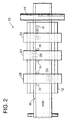
- the present invention is directed to a bag-making apparatus, designated 10, which is configured for intermittent operation as a web W of bag making material is drawn through the apparatus to make a series of bags in end-to-end relationship.
- the bag-making apparatus 10 includes a plurality of attachments which are positioned in respective operative association with the web W for effecting various manufacturing processes on the bags being made.
- the present invention contemplates that the apparatus 10 includes an auto-correction positioning system for automatically adjusting the relative positions of the attachments attendant to changes in the print repeat length of the web of bag-making material which can result from tension changes or printing variations, thus facilitating accurate high-speed operation.
- bag-making apparatus 10 includes a generally elongated attachment bed 12 which defines a web flow path along which the web W of bag-making material is moved.
- a web draw drive mechanism illustrated in the form of a pair of cooperating draw rollers 14, and an associated servo motor 16, effects intermittent drawing of the web along the attachment bed 12.
- Suitable dancer rolls and the like effect the desired tension and control of the web as it is intermittently drawn by the drive mechanism.
- a plurality of bag-making attachments are movably mounted on the attachment bed 12 along the web flow path. As noted, each of these attachments is positioned for respective association with bags being made, and thus can take various forms.
- a photoeye 20 is mounted on an attachment 22, which attachment may be "fixed" with respect to the attachment bed, thus providing the desired reference point with respect to which the other attachments are positioned.
- the attachment carrying the photoeye 20 can also be automatically adjustably positioned.
- the photoeye tracks the registration (print) marks on the bags being made, with the automatic controls of apparatus 10 adjusting the draw length effected by rollers 14 such that the mark stays in phase with the photoeye.
- Movably mounted attachments 24 and 26 are further illustrated, and may be configured to include the necessary devices for effecting various bag-making processes, such as the provision of wicket punches 28, and handle cutout unit 30.
- Each of the attachments is preferably provided with suitable wheels, skates, skids, or the like to allow rolling or sliding movement of each attachment along one or more attachment rails of the associated attachment bed 12.
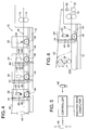
- An additional attachment 32 (see FIGURE 4) can be provided to carry a scanner of the present automated attachment positioning system, as will be described, or the scanner can be mounted on one of the attachments such as 24, 26.
- the desired conjoint translational movement of the attachments with respect to the attachment bed is effected by providing the adjustment arrangement of the present invention with a drive mechanism which effects driven movement of the attachments along the attachment bed.
- the drive mechanism includes at least one elongated gear rack 34 mounted on the attachment bed 12, with each of the attachments of the apparatus including a drive gear 36 in respective meshing engagement with the gear rack 34. It is preferred that a pair of gear racks 34 be provided on respective sides of the apparatus, with each attachment including a pair of drive gears 36 in respective engagement with the pair of gear racks. While it is preferred that each of the gears is provided with the same pitch diameter, it is within the purview of the present invention that the pitch diameter of the gears may be slightly different.
- the drive mechanism of the present auto-correction adjustment system further includes a plurality of vertically mounted gear racks 38 which are respectively mounted on each of the attachments.
- Each of the attachments is provided with a slide 40 for accommodating the sliding vertical movement of the respective one of the gear racks 38.
- each of the gear racks 38 is in meshing engagement with the respective one of the drive gears 36, whereby vertical movement of each gear rack 38 effects translation of the attachment along the attachment bed by rotation of the respective gears 36, and driven movement thereby along the elongated gear rack 34.
- the present invention can be configured such that each of the attachments includes two or more gears commonly mounted on a shaft, with one gear engaging gear rack 38, and the other gear engaging the gear rack 34. In other words, it is not necessary that the same gear 36 be in engagement with both the gear rack 38 and gear rack 34, although such an arrangement is presently preferred for simplicity and accurate positioning of the attachments.
- proportional adjustment of the attachments of the present apparatus can be effected mechanically by other than the illustrated gears and gear racks.
- a set of suitable linear cams can be provided on the one or more pivotable lever arms of the illustrated drive mechanism.
- the present adjustment system includes a pivotably mounted lever arm 42 which extends generally along the web flow path for operative connection with each of the attachments.
- the lever arm 42 is pivotal about a fulcrum thereof by operation of a suitable linear actuator 46 operatively connected with a free end of the lever (opposite its fulcrumed end).
- a suitable linear actuator 46 operatively connected with a free end of the lever (opposite its fulcrumed end).
- operation of the actuator 46 effects pivoting of the lever about its fulcrum, thereby effecting conjoint movement of gear racks 38, and thus conjoint movement of attachments 24, 26, and 32.
- Each of the gear racks 38 is linked to the lever arm 42 by a respective sliding pivot 44 which allows rotation of the gear rack with respect to the lever arm, while allowing linear displacement of the gear racks along the lever arm.
- Operation of the actuator 46 is effected by the provision of a scanner 48, mounted on one of the attachments (attachment 32 in the illustrated embodiment).
- the scanner 48 may be provided with an 8 mm. wide scanning width. It is within the purview of the present invention that the scanner 48 can be positioned upstream or downstream with respect to the fulcrum of the lever arm 42.
- the positioning of scanner 48 on one of the attachments of the apparatus is necessary to have attachment's function (handle cutout for example) on the correct position in the bag, and the scanner positioned on a registration or print mark.
- the signal generated by scanner 48 is fed to a controller of the system (FIGURE 5) which is operatively connected with the linear actuator 46, and acts to drive the actuator.
- the actuator is connected to the frame of the apparatus, or to the attachment bed 12, on one end thereof, and to the lever arm 42 on the other end thereof. Only during web stop or dwell (sealing plus some time before and sometime after) is the controller of the system armed or activated. This information is given by the main computer of the apparatus (FIGURE 5).
- the controller can move the actuator, depending upon the input it gets from the scanner 48 of the system. For example, if the scanner is downstream of the print mark, the actuator 22 will retract. This will rotate the lever arm 42 counterclockwise. The movement of the lever arm will generate a downward movement of the gear racks 38. This downward movement of the gear racks, in turn, will generate a counterclockwise movement of gears 36. As a result, the attachments (including scanner 48), will move upstream. This translational movement or displacement will continue until the scanner is on the registration mark again (if it gets there before the end of the web stop window). Because of the lever action each attachment between, or even further upstream if applicable, of scanner 48, and the fulcrum of the lever 42 will be correctly proportionately positioned.
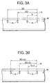
- FIGURES 3A and 3B illustrate the web of bag-making material, and the registration (or print) marks R provided therealong.
- the registration marks can, of course, be part of the print design on each bag.
- FIGURE 3A shows the web W and several of the registration marks R, with this illustration also showing the distance D between each print mark (corresponding to the print repeat length of each bag being formed).
- FIGURE 3B illustrates where the print repeat length D has changed to D plus ⁇ . This print repeat change can result from tension changes in the attachment bed area, or from printing variations.
- the dashed reference line R in FIGURES 3A and 3B is a reference line illustrating where the registration photoeye 20 of the apparatus is positioned, and provides in this first embodiment the only "fixed" point in the attachment area.
- the upstream or downstream distance between two registration marks R changes by the dimension D
- the upstream or downstream distance between two marks changes with D plus ⁇ .
- An attachment of the apparatus working on a bag which is one registration mark upstream needs a correction of ⁇ .
- An attachment working on two bags upstream needs a proportional adjustment or correction of 2 ⁇ , etc.
- the action of the lever 42 provides proportional correction of the various attachments of the bag-making apparatus. Because of the lever action, each attachment between (or even further upstream, if applicable) of the attachment carrying scanner 48 and the fulcrum of the lever will get a proportional correction, depending on its relative position along the length of the lever. By way of example, if an attachment of the apparatus is positioned at two times D from the fulcrum of the lever 42, and the scanner 48 is positioned at seven times D from the fulcrum, the aforementioned attachment will only receive a correction of two-sevenths of the adjustment effected upon the attachment carrying the scanner.
- FIGURE 6 A variation of the present invention is illustrated in FIGURE 6, wherein the photoeye 20 of the system is mounted on its own moveable attachment 22', which attachment 22' is proportionately translated together with the other attachments of the auto-correction system.
- the photoeye 20 may be mounted on one of the other attachments of the apparatus, rather than on its own attachment, as illustrated for clarity.
- the fulcrum of lever arm 42 is positioned in vertical alignment and fixed with respect to a sealing mechanism of the bag-making apparatus.
- An exemplary sealing mechanism is illustrated in FIGURE 6, as including seal bar 50 and seal bar 52. As is illustrated, the fulcrum of the lever arm is approximately in the vertical center of the sealing mechanism.
- each movable attachment can be provided with a servo drive motor, such as illustrated at 142 in FIGURE 4 in connection with attachments 24, 26.
- Each servo motor can be configured to drive an associated one of the drive gears 36, or arranged to otherwise effect movement of the attachment along the attachment bed, with operation of the servo motors effected by the automatic controls of the auto-correction system.
- a number of three-roll S-wrap mechanisms such as illustrated in phantom line at 236 in FIGURE 6, can be in association with fixedly positioned attachments.
- One of the S-wrap mechanisms can be provided between each pair of the attachments for which relative adjustment in the position of the attachments and the bag web is desired.
- a pivotable lever arm such as 42 can then be employed to move the middle roller of each S-wrap vertically up and down to accumulate or release web. While this arrangement can achieve the desired degree of accuracy, the inertia of the plural rolls such a system entails can impact upon its application in the present type of intermittent motion bag-making apparatus.
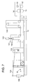
- FIGURE 7 A modified embodiment of the auto-correction system of the present invention is illustrated in FIGURE 7.
- the system is illustrated in association with a movable, vertical three-roller S-wrap 100 positioned on attachment rail 12.
- This type of arrangement for example, involves a center-fold gusset-former.
- use of the present auto-correction system in the form previously described would result in attachments positioned upstream of the S-wrap 100 being incorrectly positioned because of the web accumulated in the S-wrap 100.
- FIGURE 7 illustrates a modified embodiment of the present invention to overcome the above problem.
- a three-roller S-wrap is positioned further upstream of the S-wrap 100.
- the top roller 102 of the S-wrap can be moved, preferably up and down (i.e., vertically) by means of a linear actuator 103.
- a scanner 104 registers the print or registration mark R on the web W during web stop or dwell.
- the top roller 102 is moved up or down in order to phase the registration mark to the scanner.
- a second auto-correction system as described hereinabove (including lever arm 105, scanner 107, and an actuator 106 for moving the lever arm in response to signals from the scanner 107), with the fulcrum of the lever arm approximately in vertical alignment with scanner 104, all attachments further upstream of S-wrap 100 will be positioned correctly.
Landscapes
- Making Paper Articles (AREA)
- Auxiliary Devices For And Details Of Packaging Control (AREA)
Applications Claiming Priority (2)
| Application Number | Priority Date | Filing Date | Title |
|---|---|---|---|
| US770758 | 1991-10-04 | ||
| US08/770,758 US5733236A (en) | 1996-12-19 | 1996-12-19 | Bag-making apparatus having automated positioning of attachments |
Publications (3)
| Publication Number | Publication Date |
|---|---|
| EP0849072A2 true EP0849072A2 (de) | 1998-06-24 |
| EP0849072A3 EP0849072A3 (de) | 1999-12-01 |
| EP0849072B1 EP0849072B1 (de) | 2002-08-07 |
Family
ID=25089598
Family Applications (1)
| Application Number | Title | Priority Date | Filing Date |
|---|---|---|---|
| EP97203792A Expired - Lifetime EP0849072B1 (de) | 1996-12-19 | 1997-12-03 | Beutelherstellungsapparat mit automatisches Positionssystem von Anschlusselementen |
Country Status (8)
| Country | Link |
|---|---|
| US (1) | US5733236A (de) |
| EP (1) | EP0849072B1 (de) |
| JP (1) | JPH10180904A (de) |
| AU (1) | AU728066B2 (de) |
| BR (1) | BR9705647A (de) |
| CA (1) | CA2221643C (de) |
| DE (1) | DE69714558T2 (de) |
| ES (1) | ES2184027T3 (de) |
Cited By (1)
| Publication number | Priority date | Publication date | Assignee | Title |
|---|---|---|---|---|
| CN102189713A (zh) * | 2011-04-13 | 2011-09-21 | 浙江邦泰机械有限公司 | 一种全自动高速制袋机 |
Families Citing this family (21)
| Publication number | Priority date | Publication date | Assignee | Title |
|---|---|---|---|---|
| US6342611B1 (en) * | 1997-10-10 | 2002-01-29 | Cytovia, Inc. | Fluorogenic or fluorescent reporter molecules and their applications for whole-cell fluorescence screening assays for capsases and other enzymes and the use thereof |
| DE19856648A1 (de) | 1998-12-09 | 2000-06-15 | Lemo Maschb Gmbh | Verfahren und Vorrichtung zum Positionieren von mehreren, entlang einer Bewegungsstrecke einer Materialbahn, insbesondere einer Kunststoffolienbahn, mit Abstand zueinander angeordnete Bearbeitungsgeräten |
| US6352497B1 (en) * | 1999-04-02 | 2002-03-05 | Kimberly-Clark Worldwide, Inc. | Detectable marks in trim material |
| DK1170217T3 (da) * | 2000-07-07 | 2003-09-15 | Tetra Laval Holdings & Finance | Enhed til bearbejdelse af en bane af emballeringsmateriale til fremstilling af forseglede pakninger af flydende fødevarer |
| US6623412B2 (en) * | 2000-11-03 | 2003-09-23 | Ro-An Industries Corp. | Bag making machine with web tension control and method |
| NZ513589A (en) * | 2001-08-15 | 2004-03-26 | Machinery Developments Ltd | Packaging apparatus wherein one or more packaging devices are on sliding 'drawers' and can be moved to facilitate servicing. |
| ITMI20060184A1 (it) * | 2006-02-03 | 2007-08-04 | Mobert Srl | Dispositivo e metodo di controllo automatico di maniglie di sacchetti di plastica |
| JP5256715B2 (ja) * | 2007-12-04 | 2013-08-07 | 大日本印刷株式会社 | 袋の製造管理方法、袋の製造管理装置及び袋の製造管理装置の制御プログラム |
| DE102010029139A1 (de) * | 2010-05-19 | 2011-11-24 | Windmöller & Hölscher Kg | Vorrichtung und Verfahren zur Erzeugung von Schlauchabschnitten zur Herstellung von Beuteln |
| JP6137727B2 (ja) * | 2013-03-26 | 2017-05-31 | 大日本印刷株式会社 | 製袋機 |
| NO2848399T3 (de) * | 2013-09-13 | 2018-02-10 | ||
| DE102014107031A1 (de) * | 2014-05-19 | 2015-11-19 | Kama Gmbh | Faltstation und Faltschachtelklebemaschine |
| CN107531379B (zh) | 2015-04-29 | 2019-05-03 | 印刷包装国际有限责任公司 | 用于形成包装的方法和系统 |
| WO2017072072A1 (en) * | 2015-10-29 | 2017-05-04 | Tetra Laval Holdings & Finance S.A. | Arrangement and method for processing a web of packaging material, and a packaging material |
| CN105946288A (zh) * | 2016-06-16 | 2016-09-21 | 江苏宇驰包装股份有限公司 | 一种多功能多层纸袋、纸塑袋、编织袋自动化制袋生产线 |
| JP6821966B2 (ja) * | 2016-06-22 | 2021-01-27 | 大日本印刷株式会社 | 製袋機およびその制御方法 |
| WO2019032436A1 (en) | 2017-08-09 | 2019-02-14 | Graphic Packaging International, Llc | METHOD AND SYSTEM FOR FORMING PACKAGINGS |
| MX2021000248A (es) * | 2018-07-09 | 2021-03-25 | Graphic Packaging Int Llc | Metodo y sistema para formar envases. |
| USD1042113S1 (en) | 2020-01-24 | 2024-09-17 | Graphic Packaging International, Llc | Reinforcing carton |
| CN116133834B (zh) * | 2020-09-25 | 2025-11-07 | 户谷技研工业株式会社 | 制袋机 |
| CN116080137A (zh) * | 2023-02-08 | 2023-05-09 | 武汉领先纸品有限责任公司 | 一种包装盒外套压痕冲压装置 |
Family Cites Families (4)
| Publication number | Priority date | Publication date | Assignee | Title |
|---|---|---|---|---|
| US2321647A (en) * | 1939-09-21 | 1943-06-15 | Us Envelope Co | Apparatus for making containers |
| US3454447A (en) * | 1964-08-05 | 1969-07-08 | Nat Distillers Chem Corp | Bag-making machinery |
| US3545447A (en) * | 1968-07-17 | 1970-12-08 | Jack J Silverman | Heel stabilizer |
| CH650722A5 (fr) * | 1983-02-21 | 1985-08-15 | Bobst Sa | Machine pour confectionner des boites pliantes. |
-
1996
- 1996-12-19 US US08/770,758 patent/US5733236A/en not_active Expired - Lifetime
-
1997
- 1997-11-20 CA CA002221643A patent/CA2221643C/en not_active Expired - Fee Related
- 1997-12-03 EP EP97203792A patent/EP0849072B1/de not_active Expired - Lifetime
- 1997-12-03 DE DE69714558T patent/DE69714558T2/de not_active Expired - Lifetime
- 1997-12-03 ES ES97203792T patent/ES2184027T3/es not_active Expired - Lifetime
- 1997-12-16 BR BR9705647A patent/BR9705647A/pt not_active IP Right Cessation
- 1997-12-17 AU AU48442/97A patent/AU728066B2/en not_active Ceased
- 1997-12-19 JP JP9350931A patent/JPH10180904A/ja active Pending
Cited By (2)
| Publication number | Priority date | Publication date | Assignee | Title |
|---|---|---|---|---|
| CN102189713A (zh) * | 2011-04-13 | 2011-09-21 | 浙江邦泰机械有限公司 | 一种全自动高速制袋机 |
| CN102189713B (zh) * | 2011-04-13 | 2013-10-16 | 浙江邦泰机械有限公司 | 一种全自动高速制袋机 |
Also Published As
| Publication number | Publication date |
|---|---|
| EP0849072A3 (de) | 1999-12-01 |
| EP0849072B1 (de) | 2002-08-07 |
| ES2184027T3 (es) | 2003-04-01 |
| US5733236A (en) | 1998-03-31 |
| AU4844297A (en) | 1998-06-25 |
| CA2221643A1 (en) | 1998-06-19 |
| JPH10180904A (ja) | 1998-07-07 |
| BR9705647A (pt) | 1999-05-18 |
| CA2221643C (en) | 2004-03-02 |
| DE69714558D1 (de) | 2002-09-12 |
| AU728066B2 (en) | 2001-01-04 |
| MX9710322A (es) | 1998-08-30 |
| DE69714558T2 (de) | 2003-05-08 |
Similar Documents
| Publication | Publication Date | Title |
|---|---|---|
| US5733236A (en) | Bag-making apparatus having automated positioning of attachments | |
| US5765460A (en) | Paper cutter for variable format | |
| US8960059B2 (en) | Variable folding system comprising linear drives, especially for printing machines | |
| EP0868998B1 (de) | Hochgeschwindigkeitsmaschine für Bahnen | |
| DE69610756T2 (de) | Vorrichtung zum Ausrichten von Bahnen | |
| US5447486A (en) | Maintaining perforation phasing | |
| US5417638A (en) | Method and apparatus for maintaining proper perforation phasing | |
| GB2272982A (en) | Maintaining perforation phasing | |
| JP5802359B2 (ja) | 印刷物を自動的に切断するための切断装置 | |
| US6871571B2 (en) | Web or sheet-fed apparatus having high-speed mechanism for simultaneous X,Y and theta registration | |
| US4989855A (en) | Device for positioning plate-shaped pieces during their transfer into a processing machine | |
| US6666122B2 (en) | Web or sheet-fed apparatus having high-speed mechanism for simultaneous X, Y and θ registration and method | |
| JP7607130B2 (ja) | 変換機械のための反転転移モジュール | |
| EP3831753A1 (de) | Intermittierende transportvorrichtung | |
| US6623411B2 (en) | Bag-making machine with web alignment control | |
| US4504336A (en) | Tab applying method and apparatus | |
| US3678812A (en) | Bag machine | |
| US3678813A (en) | Bag machine | |
| JP3420039B2 (ja) | 型抜き装置 | |
| MXPA97010322A (en) | Apparatus to make bags that has automatic accessor placement | |
| US20040211807A1 (en) | Tear-off device for continuous materials | |
| US20090272287A1 (en) | Cutting Register Control | |
| CN116529189B (en) | Reverse transfer module for a converting machine | |
| WO2025254060A1 (ja) | 製袋機および製袋方法 | |
| US20040206468A1 (en) | Tear-off device for continuous materials |
Legal Events
| Date | Code | Title | Description |
|---|---|---|---|
| PUAI | Public reference made under article 153(3) epc to a published international application that has entered the european phase |
Free format text: ORIGINAL CODE: 0009012 |
|
| 17P | Request for examination filed |
Effective date: 19971203 |
|
| AK | Designated contracting states |
Kind code of ref document: A2 Designated state(s): BE DE DK ES FR GB IT |
|
| AX | Request for extension of the european patent |
Free format text: AL;LT;LV;MK;RO;SI |
|
| K1C1 | Correction of patent application (title page) published |
Effective date: 19980624 |
|
| RAP1 | Party data changed (applicant data changed or rights of an application transferred) |
Owner name: FMC CORPORATION (UK) LIMITED Owner name: FMC CORPORATION |
|
| PUAL | Search report despatched |
Free format text: ORIGINAL CODE: 0009013 |
|
| AK | Designated contracting states |
Kind code of ref document: A3 Designated state(s): AT BE CH DE DK ES FI FR GB GR IE IT LI LU MC NL PT SE |
|
| AX | Request for extension of the european patent |
Free format text: AL;LT;LV;MK;RO;SI |
|
| AKX | Designation fees paid |
Free format text: BE DE DK ES FR GB IT |
|
| 17Q | First examination report despatched |
Effective date: 20000725 |
|
| GRAG | Despatch of communication of intention to grant |
Free format text: ORIGINAL CODE: EPIDOS AGRA |
|
| GRAG | Despatch of communication of intention to grant |
Free format text: ORIGINAL CODE: EPIDOS AGRA |
|
| GRAH | Despatch of communication of intention to grant a patent |
Free format text: ORIGINAL CODE: EPIDOS IGRA |
|
| RAP1 | Party data changed (applicant data changed or rights of an application transferred) |
Owner name: HUDSON-SHARP MACHINE COMPANY |
|
| GRAH | Despatch of communication of intention to grant a patent |
Free format text: ORIGINAL CODE: EPIDOS IGRA |
|
| GRAA | (expected) grant |
Free format text: ORIGINAL CODE: 0009210 |
|
| AK | Designated contracting states |
Kind code of ref document: B1 Designated state(s): BE DE DK ES FR GB IT |
|
| REG | Reference to a national code |
Ref country code: GB Ref legal event code: FG4D |
|
| REF | Corresponds to: |
Ref document number: 69714558 Country of ref document: DE Date of ref document: 20020912 |
|
| PG25 | Lapsed in a contracting state [announced via postgrant information from national office to epo] |
Ref country code: DK Free format text: LAPSE BECAUSE OF FAILURE TO SUBMIT A TRANSLATION OF THE DESCRIPTION OR TO PAY THE FEE WITHIN THE PRESCRIBED TIME-LIMIT Effective date: 20021107 |
|
| PGFP | Annual fee paid to national office [announced via postgrant information from national office to epo] |
Ref country code: BE Payment date: 20030219 Year of fee payment: 6 |
|
| ET | Fr: translation filed | ||
| REG | Reference to a national code |
Ref country code: ES Ref legal event code: FG2A Ref document number: 2184027 Country of ref document: ES Kind code of ref document: T3 |
|
| PLBE | No opposition filed within time limit |
Free format text: ORIGINAL CODE: 0009261 |
|
| STAA | Information on the status of an ep patent application or granted ep patent |
Free format text: STATUS: NO OPPOSITION FILED WITHIN TIME LIMIT |
|
| 26N | No opposition filed |
Effective date: 20030508 |
|
| PG25 | Lapsed in a contracting state [announced via postgrant information from national office to epo] |
Ref country code: BE Free format text: LAPSE BECAUSE OF NON-PAYMENT OF DUE FEES Effective date: 20031231 |
|
| BERE | Be: lapsed |
Owner name: *HUDSON-SHARP MACHINE CY Effective date: 20031231 |
|
| REG | Reference to a national code |
Ref country code: FR Ref legal event code: PLFP Year of fee payment: 19 |
|
| REG | Reference to a national code |
Ref country code: DE Ref legal event code: R079 Ref document number: 69714558 Country of ref document: DE Free format text: PREVIOUS MAIN CLASS: B31B0019740000 Ipc: B31B0070740000 |
|
| REG | Reference to a national code |
Ref country code: FR Ref legal event code: PLFP Year of fee payment: 20 |
|
| PG25 | Lapsed in a contracting state [announced via postgrant information from national office to epo] |
Ref country code: IT Free format text: LAPSE BECAUSE OF NON-PAYMENT OF DUE FEES Effective date: 20151203 |
|
| PGFP | Annual fee paid to national office [announced via postgrant information from national office to epo] |
Ref country code: GB Payment date: 20161228 Year of fee payment: 20 |
|
| PGFP | Annual fee paid to national office [announced via postgrant information from national office to epo] |
Ref country code: ES Payment date: 20161227 Year of fee payment: 20 Ref country code: FR Payment date: 20161227 Year of fee payment: 20 |
|
| PGFP | Annual fee paid to national office [announced via postgrant information from national office to epo] |
Ref country code: DE Payment date: 20161229 Year of fee payment: 20 |
|
| PG25 | Lapsed in a contracting state [announced via postgrant information from national office to epo] |
Ref country code: IT Free format text: LAPSE BECAUSE OF NON-PAYMENT OF DUE FEES Effective date: 20151203 |
|
| PGFP | Annual fee paid to national office [announced via postgrant information from national office to epo] |
Ref country code: IT Payment date: 20161222 Year of fee payment: 20 |
|
| PGRI | Patent reinstated in contracting state [announced from national office to epo] |
Ref country code: IT Effective date: 20170710 |
|
| REG | Reference to a national code |
Ref country code: DE Ref legal event code: R071 Ref document number: 69714558 Country of ref document: DE |
|
| REG | Reference to a national code |
Ref country code: GB Ref legal event code: PE20 Expiry date: 20171202 |
|
| PG25 | Lapsed in a contracting state [announced via postgrant information from national office to epo] |
Ref country code: GB Free format text: LAPSE BECAUSE OF EXPIRATION OF PROTECTION Effective date: 20171202 |
|
| REG | Reference to a national code |
Ref country code: ES Ref legal event code: FD2A Effective date: 20180508 |
|
| PG25 | Lapsed in a contracting state [announced via postgrant information from national office to epo] |
Ref country code: ES Free format text: LAPSE BECAUSE OF EXPIRATION OF PROTECTION Effective date: 20171204 |