EP0849191A1 - Verriegelungseinrichtung, Behälter für Abfallsammler, Abfallsammler und Sammelsystem - Google Patents
Verriegelungseinrichtung, Behälter für Abfallsammler, Abfallsammler und Sammelsystem Download PDFInfo
- Publication number
- EP0849191A1 EP0849191A1 EP97403103A EP97403103A EP0849191A1 EP 0849191 A1 EP0849191 A1 EP 0849191A1 EP 97403103 A EP97403103 A EP 97403103A EP 97403103 A EP97403103 A EP 97403103A EP 0849191 A1 EP0849191 A1 EP 0849191A1
- Authority
- EP
- European Patent Office
- Prior art keywords
- locking
- tank
- ramp
- elevation
- blocking
- Prior art date
- Legal status (The legal status is an assumption and is not a legal conclusion. Google has not performed a legal analysis and makes no representation as to the accuracy of the status listed.)
- Ceased
Links
- 230000000903 blocking effect Effects 0.000 claims abstract description 33
- 230000007246 mechanism Effects 0.000 claims abstract description 22
- 230000005540 biological transmission Effects 0.000 claims abstract description 9
- 239000002699 waste material Substances 0.000 claims description 12
- 239000000463 material Substances 0.000 claims description 9
- 210000000056 organ Anatomy 0.000 claims description 9
- 230000002441 reversible effect Effects 0.000 claims description 9
- 229910000831 Steel Inorganic materials 0.000 claims description 4
- 230000001154 acute effect Effects 0.000 claims description 4
- 239000010959 steel Substances 0.000 claims description 4
- 239000002184 metal Substances 0.000 claims description 3
- 238000004873 anchoring Methods 0.000 description 5
- 230000000694 effects Effects 0.000 description 5
- 238000006073 displacement reaction Methods 0.000 description 4
- 238000012423 maintenance Methods 0.000 description 4
- 239000010813 municipal solid waste Substances 0.000 description 4
- 230000000295 complement effect Effects 0.000 description 3
- 239000000470 constituent Substances 0.000 description 3
- 238000000926 separation method Methods 0.000 description 2
- 230000004308 accommodation Effects 0.000 description 1
- 230000008878 coupling Effects 0.000 description 1
- 238000010168 coupling process Methods 0.000 description 1
- 238000005859 coupling reaction Methods 0.000 description 1
- 230000002349 favourable effect Effects 0.000 description 1
- 230000010354 integration Effects 0.000 description 1
- 230000014759 maintenance of location Effects 0.000 description 1
- 238000007726 management method Methods 0.000 description 1
- 238000004519 manufacturing process Methods 0.000 description 1
- 238000000034 method Methods 0.000 description 1
- 239000010893 paper waste Substances 0.000 description 1
- 230000003252 repetitive effect Effects 0.000 description 1
- 230000035939 shock Effects 0.000 description 1
- 229910001220 stainless steel Inorganic materials 0.000 description 1
- 239000010935 stainless steel Substances 0.000 description 1
Images

Classifications
-
- B—PERFORMING OPERATIONS; TRANSPORTING
- B65—CONVEYING; PACKING; STORING; HANDLING THIN OR FILAMENTARY MATERIAL
- B65F—GATHERING OR REMOVAL OF DOMESTIC OR LIKE REFUSE
- B65F1/00—Refuse receptacles; Accessories therefor
- B65F1/14—Other constructional features; Accessories
- B65F1/141—Supports, racks, stands, posts or the like for holding refuse receptacles
-
- E—FIXED CONSTRUCTIONS
- E05—LOCKS; KEYS; WINDOW OR DOOR FITTINGS; SAFES
- E05B—LOCKS; ACCESSORIES THEREFOR; HANDCUFFS
- E05B53/00—Operation or control of locks by mechanical transmissions, e.g. from a distance
- E05B53/003—Operation or control of locks by mechanical transmissions, e.g. from a distance flexible
-
- E—FIXED CONSTRUCTIONS
- E05—LOCKS; KEYS; WINDOW OR DOOR FITTINGS; SAFES
- E05B—LOCKS; ACCESSORIES THEREFOR; HANDCUFFS
- E05B63/00—Locks or fastenings with special structural characteristics
- E05B63/14—Arrangement of several locks or locks with several bolts, e.g. arranged one behind the other
- E05B63/143—Arrangement of several locks, e.g. in parallel or series, on one or more wings
-
- E—FIXED CONSTRUCTIONS
- E05—LOCKS; KEYS; WINDOW OR DOOR FITTINGS; SAFES
- E05C—BOLTS OR FASTENING DEVICES FOR WINGS, SPECIALLY FOR DOORS OR WINDOWS
- E05C1/00—Fastening devices with bolts moving rectilinearly
- E05C1/08—Fastening devices with bolts moving rectilinearly with latching action
- E05C1/12—Fastening devices with bolts moving rectilinearly with latching action with operating handle or equivalent member moving otherwise than rigidly with the latch
-
- E—FIXED CONSTRUCTIONS
- E05—LOCKS; KEYS; WINDOW OR DOOR FITTINGS; SAFES
- E05B—LOCKS; ACCESSORIES THEREFOR; HANDCUFFS
- E05B35/00—Locks for use with special keys or a plurality of keys ; keys therefor
- E05B35/008—Locks for use with special keys or a plurality of keys ; keys therefor for simple tool-like keys
-
- E—FIXED CONSTRUCTIONS
- E05—LOCKS; KEYS; WINDOW OR DOOR FITTINGS; SAFES
- E05B—LOCKS; ACCESSORIES THEREFOR; HANDCUFFS
- E05B65/00—Locks or fastenings for special use
- E05B65/006—Locks or fastenings for special use for covers or panels
Definitions
- the invention relates to a locking device, a basket tank, a basket and a system of collection.
- the device of the invention is essentially described here as being intended for a collection basket, for example waste, due to its origin.
- a locking device has the function, to immobilize in relation to a frame or support, placed at remains or fixed, a mobile assembly such as a leaf or a container tank, for example.
- At least one locking position is provided.
- Such a device comprises means control, mobile blocking means controlled by the control means, and receiving means provided to engage with the locking means in position immobilization.
- receiving means are arranged on the frame, the means control and blocking being on the mobile assembly.
- the means of control, with the locking means, are on the frame.
- the reception means are then on the mobile assembly.
- Entry and retention must be secure, firm and efficient one way or the other, indifferently.
- While the device must be arranged to so as not to obstruct the various movements of the mobile assembly.
- connection between the fixed frame and the mobile assembly must not only allow movement, but often the separation or dismantling of this assembly.
- the assembly and disassembly must be functional, fast operations, without excessive fatigue operator, or risk of error.
- a hook of the locking device is linked to the support and mobile upright rotating around an axis vertical.
- the tank has a locking tooth with which the hook is engaged in a position of engagement, under the effect of a reminder.
- Document DE-U-7,330,880 describes a basket rigidly fixed on the support upright.
- Document EP-A-219.385 provides on the tank cover, a rear face in one piece.
- the rear face - and the amount - limits access to the tank.
- the basket becomes temporarily unavailable, both for passers-by and for maintenance.
- the rear side of such a basket is little aesthetic. Its main function is the anchoring of resources the basket.
- the tank cover offers limited protection the contents of the recycle bin, for example against severe weather.
- the mobile hook is directly linked to the means of command and requested by the recall body.
- the vertical control axis is located at the rear of the tank cover. This location is not easily accessible from the front, where an operator should be placed to control the pivoting when the tank is released (emptying).
- the means of reception consists of a concave shape with a protruding wall fine, integral with the mobile assembly, for example the back of the tank.
- the basket and the system collection meet growing requirements integration into the environment.
- the structure of the trash can be dissuasive against wild posting and graffiti.
- the invention in particular overcomes these drawbacks.
- a first object of the invention is a locking device, for example intended for a collection basket.
- This device makes it possible to immobilize with respect to a said fixed support such as a permanently placed frame, a mobile assembly such as a tank.
- Connection means such as a joint swivel, being arranged between the fixed support and the mobile assembly.
- the latter is movable according to a trajectory, between a locked position and at least a release position, in which the mobile assembly is capable of possibly being separated from the support fixed.
- Blocking means such as “bolt”, controlled by control means and biased towards their position locking by return means, are integral of the frame.
- While means of reception or "waste” are arranged on the mobile assembly, to cooperate with the locking means in the locking position.
- the connecting means are arranged to allow movement (clearance and engagement) of the mobile assembly according to two opposite directions of the trajectory, on both sides from a locking position.
- the reception means comprise at least one ramp - and for example two ramps - next to means of locking in locking position, rigidly secured of the movable assembly, for example of an edge or mouth access to the tank.
- the generally extended ramp following the trajectory is provided with a form of immobilization of blocking means, and on either side of this form along the trajectory, with an introductory bevel, one of which acute end is respectively opposite to the shape immobilization.
- the ramp has a structure asymmetrical with respect to a plane perpendicular to the trajectory and parallel to a corresponding direction of solicitation of recall means on both sides of the form of immobilization following the trajectory.
- the form immobilizer also has an asymmetrical shape in the same plane, with on the one hand a high support front, forming the main stop, and on the other hand a front of low clearance, reduced in size compared to the front high, following the direction of solicitation.
- the high front is substantially adjacent to a ramp bevel, while the low front is connected to the other ramp bevel by through an introductory bevel preferential, substantially parallel to or oriented close to that of the contiguous bevel.
- the ramp is at least in part of material with the mobile assembly and / or a insert made of wear-resistant material such as metal like steel or the like, is part of the ramp, the insert being for example embedded in the mobile assembly.
- the blocking means include at least one finger, one free end of which is engaged with a form of immobilization of the means of reception in the locked position, this finger having along a plane substantially parallel to the trajectory and / or to the recall request direction, a profile substantially symmetrical end, for example trapezoidal.
- the means of blocking have at least two autonomous mechanisms, distance from each other as well as from control means common, and each provided with its own recall means.
- the reception means then comprise a ramp, opposite each locking mechanism in position locking, and rigidly secured to the assembly mobile, for example from an access edge to the tank, the means being provided, for each mechanism, with a flexible transmission element capable of transmitting to the corresponding mechanism of tensile stresses exclusively, in a direction opposite to that of solicitation of its recall means, from the means of command common to these mechanisms.
- the control means are pivotable, and include a lever, connected to each element of transmission which is capable of exerting traction, respectively, via angle return means possibly on the blocking means which are displaceable in rectilinear translation.
- One embodiment provides two blocking mechanisms and own recall means, disposed respectively of on either side of the mobile assembly relative to the path.
- control means are locally extended substantially parallel to the trajectory and / or a direction of solicitation of the recall means.
- control means are locally extended in an elevation direction substantially of centrally between the two own recall means and / or in a transverse direction, away from the reception means according to the direction of solicitation, in the locked position.
- connection and blocking are arranged substantially symmetrical about a central plane, substantially parallel to the trajectory and to a direction of solicitation and / or control means so as to be reversible at engagement.
- connection and blocking are arranged substantially symmetrical about a central axis, substantially perpendicular to the trajectory and / or parallel to a load direction, so as to be reversible to engagement.
- Another object of the invention is a trash, for example waste collection, intended for be equipped with at least one locking device such that mentioned.
- This tank is provided, according to one embodiment, a substantially extended access mouth perpendicular to an elevation direction, following which the tank is generally placed in the position of locking, and / or at least one member of the means of connection, such as a hinge feed, and for example two, near an end opposite the mouth in the direction of elevation, arranged substantially at right of means of reception according to the direction elevation.
- a substantially extended access mouth perpendicular to an elevation direction, following which the tank is generally placed in the position of locking, and / or at least one member of the means of connection, such as a hinge feed, and for example two, near an end opposite the mouth in the direction of elevation, arranged substantially at right of means of reception according to the direction elevation.
- a wear pad is provided, for example central and transverse, intended to cooperate with a frame track fixed.
- the skate is arranged substantially to the right of means control according to the direction of elevation, and / or centrally between organs of the connecting means.
- the tank is substantially symmetrical about an axis parallel to an elevation and / or solicitation direction.
- Yet another object of the invention is a collection basket, for example of waste, equipped with less a locking device and / or a tank such that mentioned.
- a feature provides that the fixed frame delimits a space substantially in a closed loop, the means of connection and / or reception and / or blocking being arranged inside this space.
- the fixed frame and / or the tank includes -or essentially consists of- a plastic shell, such as rotomolded plastic or injected into the press.
- a feature provides that the fixed frame includes a connection light to the means of control, substantially at the top and / or has a hood vault fully extended projecting to the right of a tank mouth.
- An additional object of the invention is a collection system, comprising at least one collection device lock and / or a tank and / or a waste basket collection, as mentioned.
- the system comprises permanent means such as central foot and / or base transverse junction of two lateral uprights of the frame fixed.
- Figure 1 is a view in perspective of three quarters before, of a collection system with a street basket, in accordance with the invention, and provided with a central leg.
- Figure 2 is a view similar to Figure 1, which represents a system provided with an enveloping base "U” shaped with side elevation branches.
- Figure 3 is a cross-sectional view and central, a collection system, as well as a locking device according to the invention.
- Figure 4 is a transverse elevation view a collection system and basket compliant with the invention, with the tank in one of its two states of release.
- Figure 5 is a view similar to Figure 4, in unique central locking position of the tank.
- FIG. 6 is a front elevation view and partial of the system and the collection bin of the figure 4 or 5.
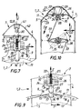
- Figure 7 is a partial sectional view side elevation of a locking device and a basket according to the invention.
- Figure 8 is a side elevational view of a ramp insert intended to be part of means of type-approval locking device the invention.
- FIG. 9 is a view similar to FIG. 7, illustrating in detail reception means and means blocking, the latter being shown in thin lines in their locked position, and in a strong line in their release position.
- Figure 10 is a partial view, in section in plane, which represents the lever of single control means and two flexible connection elements, as well as a mechanism of the locking means, with its means of fixing on the frame.
- Direction L is called lateral direction.
- the direction T is called transverse direction.
- Direction E is called elevation direction.
- the directions orthogonal lateral L and transverse T are considered here as being substantially horizontal. They jointly define a horizontal support plane L, T.
- the direction of elevation E is considered here as being substantially vertical, and therefore perpendicular to horizontal directions and plan.
- the constituents of the invention including the device lock, the bowl, the basket and the collection, described here in relation to directions L, T and E, can take different positions in space.
- the reference 1 designates a collection basket, and reference 2 a system of collection including a (in some cases not shown several) collection basket 1.
- the collection system 2 comprises means for residence 3.
- the fixing means 3 essentially include a central leg, one of which so-called upper end in the direction of elevation E, allows rigid support for a basket 1 support.
- the opposite opposite end of the central leg 1, is rigidly fixed on the horizontal support plane L, T.
- the latter generally includes a floor or covering of roads such as sidewalk, building slab, floor or the like.
- the means 3 therefore make it possible to permanently place the system 2, and consequently the trash 1, compared to the support plane L, T.
- the means for setting remains 3 include a side base too rigidly fixed to the support plane L, T.
- This base is generally in the shape of "U” in a plane defined by directions L and E, and envelope thus laterally the basket 1, in part.
- the latter notably includes a support known as fixed frame 4, rigidly secured to the setting means remains 3.
- the basket 1 also includes a set 5, movable relative to the fixed frame 4.
- Figures 4 to 6 show means of link 6, arranged between the fixed frame 4 and the assembly mobile 5.
- the connecting means 6 have the function of allow the mobile assembly 5 to be moved by relative to the fixed frame 4.
- the relative displacement of the mobile assembly 5 by relative to the fixed frame 4 is carried out according to a trajectory D shown in FIGS. 4 and 5, especially.
- connection means 6 here being pivoting, of axis substantially extended in the lateral direction L.
- the trajectory D here has the shape of an arc of a circle at large radius.
- the means 6 comprise two organs males on the mobile assembly 5, and two female organs complementary on the fixed frame 4.
- the opposite case is shown in Figures 4 to 6.
- the tangent to the trajectory D is substantially parallel to the transverse direction T.
- the trajectory D is locally a straight line parallel to the transverse direction T.
- the displacement along trajectory D is planned here between a single central locking position ( Figures 1 to 3, 5 to 7, 9 and 10), and positions release.
- Figure 4 shows the mobile assembly 5 in a extreme release position or disassembly of the assembly 5.
- the latter can also be placed, along the trajectory D, in a position of opposite extreme clearance.
- This extreme opposite position places the mobile assembly 5 symmetrically relative to to a plane parallel to direction E and passing through connecting means 6 (i.e. on the right in the figure 4).
- the connecting means 6 in particular are arranged so that in one and / or the other of the positions of disassembly, the mobile assembly 5 can be detached or dismantled from the fixed support 4.
- the means 6 then comprise removable joints.
- the general reference 7 designates a locking device.
- such a locking device 7, described here as being intended for a basket 1 or for a 2 collection system is not limited to this application, but can be intended for other structures such as furniture, doors, technical boxes, storage units for industry or the like.
- This device makes it possible to immobilize in relation to the frame 4, which is placed permanently, the assembly 5 which is mobile along trajectory D.
- the device 7 therefore makes it possible to obtain between the disassembly positions, a so-called locking position, in which the mobile assembly 4 is temporarily blocked, immobilized and locked. Its function is therefore similar to that of a lock.
- the locking device 7 comprises means 8, locking means 9, means of reminder 10 and reception means 11, mainly.
- the control means 8 make it possible to actuate the locking device 7.
- the means 8 include in particular a socket 12, intended to receive an operating key (not shown) which can itself be operated by an operator wishing to trigger the device 7.
- the socket 12 is here a female housing tool or wrench.
- the control means 8 are integral with the frame fixed 4, and include several pieces guided so to be movable or mobile, relative to the frame 4.
- the control means 8 make it possible to act on the locking means 9, also integral with the fixed frame 4.
- Certain components of the means 9 are fixed and others can be moved relative to frame 4.
- the displaceable blocking means 9 are arranged to be able to cooperate with the mobile assembly 5, in particular in the locking position of the latter.
- Means 9, comparable to a "bolt”, are also used in permanently to their locked position by return means 10, which are integral with the frame 4.
- the movable parts of the means 8 are mounted crazy, and are requested under the effect of the return means 10, via the blocking means 9 in particular.
- Recall means 10 specific to the means of command 8 can act on these directly, together with other recall means 10, specific to locking means 9.
- the return means 10 in particular refer to the means of blocking 9 in their locked position where they cooperate with the assembly 5 to immobilize it.
- the locking means 9 cooperate with the receiving means 11 which are integral with the movable assembly 5 and arranged thereon.
- the receiving means (11) comprise at least one ramp 13.
- each ramp 13 is generally extended along path D. It has a shape immobilizer 14, which allows the accommodation of a displaceable component of the locking means 9, in position lock.
- the ramp 13 On either side of the immobilization form 14 along the path D, the ramp 13 comprises two bevels introduction 15 and 16. Each introduction bevel 15 and 16 has an acute end along the path D, respectively opposite to the form of immobilization 14.
- the ramp 13 has a structure asymmetrical with respect to a plane perpendicular to the trajectory D and parallel to the direction of elevation E, confused here with a direction of solicitation of return means 10, on either side of the form 14.
- immobilization 14 delimits a housing also asymmetrical, compared to a plane perpendicular to path D, at the center of the shape 14.
- form 14 has a bearing front high, which acts as a main stop for part blocking means 9.
- the form of immobilization 14 has a low clearance front 18.
- low front 18 Due to its reduced size compared to high front 17, low front 18 has a more arrangement favorable to the release of the locking means 9 outside the means of reception 11.
- the high front 17 is here contiguous to the bevel 15 of the ramp 13.
- the bevel 15 is therefore said to be a support bevel like the contiguous front 17.
- the low front 18 is meanwhile remote from the bevel 16, and said clearance. It is separated from it by a counter-bevel 19 said to be of preferential introduction.
- the preferential introduction bevel 19 is substantially parallel to, or at least close to, that of support bevel 15 contiguous to the high front 17.
- the ramp 13 has its high front 17 substantially perpendicular to the path D. This front 17 is oriented in a direction facing the bevel 19 and the clearance bevel 16.
- the low clearance front 18 is for its part inclined with respect to the transverse directions T and elevation E. From the bottom of the form 14 towards the bevel 16, the inclined front 18 is oriented from bottom to top at an angle between 50 and 60 °, and by example of the order of 55 °.
- the device for lock 7 has two ramps 13.
- a ramp 13 (shown in solid lines) has its high front 17 oriented in a direction along the path D.
- While the high front 17 of the other ramp 13 (shown in dotted lines) is oriented in the opposite direction along the direction T or the trajectory D locally.
- the two ramps 13 of this device 7 are therefore arranged "head to tail". This also improves the locking, by distributing the forces.
- Figure 9 shows that the ramp 13 is at least in part made of material with the mobile assembly 5.
- an insert 20 shown in Figure 8 is intended to be part of the ramp 13.
- An insert 20 is in this embodiment embedded in the mobile assembly 5, for each ramp 13.
- the insert 20 is chosen from a resistant material to wear, such as a metal, for example steel or the like.
- pan 21 for anchoring to mobile assembly 5, as well as several surfaces substantially perpendicular to the anchor pan 21.
- Fastening means 22 are here provided under the form of fixing holes, for the passage of studs added material and / or anchor pins, for example such as screws, rivets or the like.
- the reference 23 represents a movable finger forming part of the means of blocking 9.
- a free end of finger 23 is engaged with immobilization form 14 in position locking. This free end is therefore the constituent blocking means 9 which cooperates with the ramp 13.
- the finger 23 has at its free end, following a plane substantially parallel to the trajectory D and to the elevation direction E, a substantially symmetrical profile trapezoidal.
- the free end of the finger 23 has two sides inclined from bottom to top and towards the center of this finger, as well as a central end face, substantially parallel to directions T and L.
- the faces inclined have a comparable orientation, or slightly more inclined with respect to the direction T, than the front low clearance 18.
- each inclined face of the end free of finger 23 has an angle of the order of 60 ° per report to management T.
- the reference 24 designates a fixed support and guide plate for finger 23.
- the support and guide plate 24 includes 25 anchoring lugs or rigid attachment to the fixed frame 4. Certain embodiments make it possible to produce the plate 24 integral with the fixed frame 4.
- the plate 24 is attached and mounted from removable way on the fixed frame 4.
- the fixing is here provided by mounting means 26, represented here by two sets of screw-nut-washers.
- the anchoring lugs 25 are arranged against a plane of the fixed frame 4 substantially parallel to the directions T and E. And the mounting means 26 are substantially extended in direction L.
- the plate 24 internally delimits a shirt guide 27, mainly elongated and extended following the direction E of elevation.
- the guide jacket 27 either came entirely from matter. Either she is closed by an attached cover 28, as in FIG. 10. Either it is still closed by a contiguous wall of the fixed frame 4.
- the shirt 27 has the function of guiding the finger 23 in translation or straight sliding according to the direction of elevation E, substantially.
- Figure 10 shows that in section following a plan parallel to the transverse T and longitudinal L directions, the inside of the guide jacket 27 has a contour substantially polygonal, here substantially square.
- the finger 23 of the locking means 9, which is also extended mainly following direction elevation E, has a complementary external contour to the inner contour of the shirt 27, following the same section. More specifically, an external guide portion of the finger 23 is of section or square with bevelled corners.
- finger 23 and of guide jacket 27 are determined to spare a certain clearance allowing sliding of the next finger 23 the direction of elevation E.
- a so-called lower end of the shirt 27 opens out opposite ramp 13, in position locking. It allows the passage of the free end finger 23.
- finger 23 is said to be upper inside the shirt 27 whatever its position. And it is arranged opposite the opening end opposite of the jacket 27, in the direction of elevation E.
- Cale 29 projects into the cavity delimited by the inside of the shirt 27.
- the sheath 29 protrudes in the lateral L and transverse directions T. Note that in the plane defined by these two directions, the section of wire 29 is much smaller than that of the cavity defined by the shirt 27.
- the cable 29 therefore leaves at least one passageway 30, which gives access to inside the shirt 27.
- return means 10 is returned integral with the shim 29.
- the shim 29 is rigidly united, but in a removable manner, in such a way end.
- Return means 10 have their opposite end in direction E secured to finger 23.
- a face in look of sheaf 29, for example perpendicular to the direction E, here acts as a support for this end.
- Such a face could be an external upper face finger tip 23.
- the recall means 10 mentioned above are entirely housed in channel 32, located inside the finger 23, between a bearing face 31 of finger 23, and the wire 29 of the support plate 24.
- damper cap 34 is interposed between the face 31 and the end opposite to the shim 29 of the means 10 mentioned.
- the plug 34 is to be considered as forming part of these means 10.
- the locking means 9 comprise at least two autonomous mechanisms, distant from each other others, as well as common control means 8. Each means 9 is provided with its own return means 10.
- Each mechanism includes a finger 23, a plate 24, mainly.
- the return means own 10 of these mechanisms locking means 9 include, in addition to the damper caps 34, each a stainless steel coil spring, mainly extended along elevation direction E and installed in the corresponding channel 32 with a finger 23.
- the reception means 11 then comprise a ramp 13, opposite each locking mechanism (23,24) in the locked position.
- the control means 8 are provided, for each mechanism, of a flexible transmission element, here a cable 33.
- Each cable 33 is at one of its free ends, rigidly attached to a finger 23.
- the cable 33 is a cable of the type "push-pull" formed of braided and sheathed steel strands.
- means of bevel gear 36, rigidly secured to the fixed frame 4, are arranged between the two free ends of each cable 33.
- the angle transmission means 36 include, to the right of each support plate 24 following the direction of elevation E, a guide cable 33, which delimits an angled gutter opening on the one hand towards a lever 35, so substantially parallel to the support plane L, T.
- the gutter leads on the other hand, and more precisely the opposite, in look at channel 32 of finger 23.
- each gutter angle return means 36 is flared, in order to allow some movement of the cable orientation 33 in the support plane L, T, between the support plate 24 and lever 35.
- Cable 33 is a flexible transmission element able to transmit to the corresponding blocking mechanism, tensile stresses exclusively.
- Figure 3 shows common control means 8 swivel.
- the sleeve 12 is rotatably mounted in additional housing for the support frame 4.
- the socket 12 is thus able to be rotated around a axis parallel to the direction of elevation.
- a stop screw 37 holds socket 12 in the direction of elevation E, relative to the fixed frame 4.
- FIGS 7 and 10 show that each cable 33 is provided at each of its free ends with a head protruding 38.
- the finger 23 has between its internal bearing face 31 and its free end, a through groove in which the cable 33 has passed. Head 38 of this end, is also arranged in this groove, of so as to make the finger 23 and the cable 33 integral, in the direction E and in an opposite direction S (figure 7) upon the request of own return means 10.
- the other cable 33 (below in FIG. 10) is stressed in the same direction of traction, but in opposite direction, when the lever 35 is rotated by the socket 12, in the counterclockwise direction.
- the maximum angle of rotation of the lever 35, designated in A, is here of the order of 45 °, from rest position to unlock position.
- the lever 35 In the locked position, as in the figure 10, the lever 35 is substantially extended according to the transverse direction T, that is to say parallel to the trajectory D.
- pivot axis of the sleeve 12 being aligned with the center of each folder 27 and each channel 32 of blocking means 9, in direction L, cable 33 is therefore locally extended at an angle in the longitudinal L and transverse T directions, between the angle return means 36 and the lever 35.
- the gutter of the means 36 is flared in the shape of a "V", in the plane parallel to the longitudinal directions L and transverse T. The point of this "V" is opposite to the socket 12, following direction L.
- each cable 33 in the locked position, is between 20 ° and 25 °, and is by example of around 22 °.
- the control means 8 which are pivotable, therefore include a lever 35, connected to each element of transmission 33, capable of exerting traction via the means angular gear 36, on the locking means 9 which are them, displaceable in rectilinear translation.
- the two blocking mechanisms and the two means own reminder 10, are arranged respectively on the hand and other of the mobile assembly 5, relative to the trajectory D.
- the common control means 8 are, for what is of lever 35, extended substantially parallel to the trajectory D, and with regard to the socket 12, substantially parallel to the load direction own return means 10, in the rest position.
- control means 8 are generally elsewhere extended in the direction of elevation E, substantially of centrally between the two own recall means 10. They are also extended according to the direction transverse T, remote from the receiving means 11 following the direction of solicitation, in the position of locking.
- This set 5 is therefore able to be locked to the fixed frame 4, from two positions, indifferently.
- the tank 5 is a rotomoulded or injected plastic part.
- the tank 5 is provided with an access edge or mouth 39 extended substantially perpendicular to the direction elevation E, according to which the tank 5 is generally arranged in the locked position.
- the tank 5 in the shape of an inverted bell, comprises elevation walls extended in direction E, as well as a bottom, of convex shape, with concavity turned towards the abutment means 3 ( Figures 4 to 6) opposite of the access port 39.
- the tank 5 is provided with external ridges 40, substantially U-shaped in a plane parallel to lateral directions L and elevation E, which limit the surfaces offered for wild posting, while participating in the rigidity of this tank.
- Bodies forming part of the connecting means 6, here two hinge feeds are provided on the tank 5 near an end opposite the mouth 39, according to the direction of elevation E.
- the organs of the connecting means 6 are arranged substantially to the right of the reception means 11, according to the direction of elevation E. In the plane defined by the directions L and E, the organs of the connecting means 6 are therefore arranged on either side of the tank 5, according to the lateral direction L.
- a wear pad for example central and transverse, is provided at one end of the opposite tank 5 at the access port 39, in the direction of elevation E.
- This wear pad is intended to cooperate with a complementary track of the fixed frame 4.
- the wear pad is for example in the form of a strip projecting from the outer bottom of tank 5.
- the tank 5 is here substantially symmetrical by relative to a central axis parallel to the direction elevation E.
- Collection basket 1 for example for collection of waste such as fatty paper or the like, is equipped with at least one locking device 7 and minus a tank 5 as mentioned.
- the fixed frame 4 delimits a space substantially in closed loop, inside which the means are arranged 6, and the receiving means 11, the means of blocking 9 as well as most of the control means 8.
- the fixed frame 4 is essentially constituted by a shell in material synthetic, for example rotational molded or injected hurry.
- the fixed frame 4 includes a light 41 of connection to control means 8, substantially at its Mountain peak.
- Light 41 substantially central, is provided on a cover 42 of the fixed frame 4.
- the cover 42 is, as this emerges from Figures 1 to 6, in the form of an extended arch protruding from the mouth 39 of the tank 5.
- Such a basket 1 integrates with the means of delivery 3, to the collection system 2.
- moving from one position to another corresponds to the angle A of the order of 30 ° to 60 °, and by example of the order of 45 °.
- each finger 23 is raised in direction S (or direction E) from its dotted position in Figure 9 to its solid line position. In this last position the free trapezoid end of finger 23 is at a distance of the corresponding ramp 13.
- the tank 5 which is mounted madly or slightly braked to rotate on the connecting means 6, can then be pivoted about an axis parallel to the direction L, in the direction illustrated in Figure 4 -or in the direction opposite - along the path D. In such a position of clearance, the interior of the tank 5 can be viewed.
- the tank can be separated from frame 4, for example to be emptied. To do this, simply lift it so that separate the male and female organs from the connecting means 6.
- the mounting of the tank 5 on the frame 4 consists of a reverse movement, in the disassembly position, and more precisely in one of the two dismantling positions possible since the tank 5 is reversible.
- control means 8 have been actuated simply to release the finger 23 out of the shape 14.
- the fingers 23 return after being released, in position in which they can be re-engaged with form 14, in the locked position.
- the tank 5 Once the tank 5 is put back on the fixed frame 4, it just rotate it in reverse to first bring fingers 23 into contact with one bevels 15 or 16, respectively, of this tank. In continuing the movement, the return means 10 are compressed which causes displacement following the direction S of fingers 23.
Landscapes
- Engineering & Computer Science (AREA)
- Mechanical Engineering (AREA)
- Structural Engineering (AREA)
- Refuse Receptacles (AREA)
Applications Claiming Priority (2)
| Application Number | Priority Date | Filing Date | Title |
|---|---|---|---|
| FR9615772A FR2757559B1 (fr) | 1996-12-20 | 1996-12-20 | Dispositif de verrouillage, cuve de corbeille, corbeille et systeme de collecte |
| FR9615772 | 1996-12-20 |
Publications (1)
| Publication Number | Publication Date |
|---|---|
| EP0849191A1 true EP0849191A1 (de) | 1998-06-24 |
Family
ID=9498937
Family Applications (1)
| Application Number | Title | Priority Date | Filing Date |
|---|---|---|---|
| EP97403103A Ceased EP0849191A1 (de) | 1996-12-20 | 1997-12-19 | Verriegelungseinrichtung, Behälter für Abfallsammler, Abfallsammler und Sammelsystem |
Country Status (2)
| Country | Link |
|---|---|
| EP (1) | EP0849191A1 (de) |
| FR (1) | FR2757559B1 (de) |
Cited By (1)
| Publication number | Priority date | Publication date | Assignee | Title |
|---|---|---|---|---|
| US6455222B1 (en) | 1999-03-24 | 2002-09-24 | Fuji Photo Film Co., Ltd. | Lithographic printing plate precursor |
Families Citing this family (1)
| Publication number | Priority date | Publication date | Assignee | Title |
|---|---|---|---|---|
| FR2881725B1 (fr) * | 2005-02-07 | 2008-10-10 | Plastic Omnium Cie | Conteneur, notamment de reception et/ou de collecte de dechets, tel qu'une corbeille a papier. |
Citations (6)
| Publication number | Priority date | Publication date | Assignee | Title |
|---|---|---|---|---|
| DE2259701A1 (de) * | 1972-12-06 | 1974-06-12 | Henry Z Golan | Werbeflaechen tragender oeffentlicher abfallsammler |
| FR2559826A1 (fr) * | 1984-02-21 | 1985-08-23 | Bracq Daniel | Serrure de volet roulant |
| FR2565946A1 (fr) * | 1984-06-14 | 1985-12-20 | Smedt Francis De | Poubelle |
| EP0219385A2 (de) * | 1985-09-18 | 1987-04-22 | Allibert Sa. | Papierkorb |
| GB2217182A (en) * | 1988-04-25 | 1989-10-25 | Andrew Saint Nicholas Hibbert | Rubbish bin assembly |
| DE9016015U1 (de) * | 1990-11-24 | 1991-02-07 | Greschbach Industrie GmbH & Co, 7834 Herbolzheim | Abfall-Sammelvorrichtung |
-
1996
- 1996-12-20 FR FR9615772A patent/FR2757559B1/fr not_active Expired - Fee Related
-
1997
- 1997-12-19 EP EP97403103A patent/EP0849191A1/de not_active Ceased
Patent Citations (6)
| Publication number | Priority date | Publication date | Assignee | Title |
|---|---|---|---|---|
| DE2259701A1 (de) * | 1972-12-06 | 1974-06-12 | Henry Z Golan | Werbeflaechen tragender oeffentlicher abfallsammler |
| FR2559826A1 (fr) * | 1984-02-21 | 1985-08-23 | Bracq Daniel | Serrure de volet roulant |
| FR2565946A1 (fr) * | 1984-06-14 | 1985-12-20 | Smedt Francis De | Poubelle |
| EP0219385A2 (de) * | 1985-09-18 | 1987-04-22 | Allibert Sa. | Papierkorb |
| GB2217182A (en) * | 1988-04-25 | 1989-10-25 | Andrew Saint Nicholas Hibbert | Rubbish bin assembly |
| DE9016015U1 (de) * | 1990-11-24 | 1991-02-07 | Greschbach Industrie GmbH & Co, 7834 Herbolzheim | Abfall-Sammelvorrichtung |
Cited By (1)
| Publication number | Priority date | Publication date | Assignee | Title |
|---|---|---|---|---|
| US6455222B1 (en) | 1999-03-24 | 2002-09-24 | Fuji Photo Film Co., Ltd. | Lithographic printing plate precursor |
Also Published As
| Publication number | Publication date |
|---|---|
| FR2757559B1 (fr) | 1999-05-07 |
| FR2757559A1 (fr) | 1998-06-26 |
Similar Documents
| Publication | Publication Date | Title |
|---|---|---|
| EP0925996B1 (de) | Fahrzeugsitzeinheit mit auf Gleitschienen montiertem, abnehmbarem Sitz | |
| EP2049391B1 (de) | Gepäckschliessfach und entsprechende tür, im besonderen für ein flugzeug | |
| EP0374056A2 (de) | Alpinskischuh der Bauart mit rückwärtigem Einstieg | |
| FR2829439A1 (fr) | Pietement de siege de vehicule, siege comportant un tel pietement et ensemble d'assise comportant un tel siege | |
| CA1265693A (fr) | Dispositif de verrouillage de tampon de regard de chaussee | |
| FR2595951A1 (fr) | Ensemble constitue par une chaussure de ski de fond ou de randonnee et un dispositif de retenue de l'avant de cette chaussure sur un ski | |
| EP0219385B1 (de) | Papierkorb | |
| WO2003053186A2 (fr) | Poignee telescopique pivotable | |
| FR2585935A1 (fr) | Ensemble pour le conditionnement et la presentation d'au moins un produit solide, notamment d'au moins un pain de substance cosmetique | |
| EP1835078B1 (de) | Strassenausstattung | |
| EP0849191A1 (de) | Verriegelungseinrichtung, Behälter für Abfallsammler, Abfallsammler und Sammelsystem | |
| EP0470383A1 (de) | Skischuh | |
| FR2956021A1 (fr) | Poignee amovible d'ustensile de cuisine comportant deux pattes mobiles de serrage | |
| FR2707962A1 (fr) | Dispositif de blocage pour conteneur mobile de collecte d'ordures ménagères. | |
| FR2673967A1 (fr) | Armoire a porte verrouillable et retournable. | |
| FR2629996A1 (fr) | Ecran adaptable a une baignoire, integrant un dispositif de coulissement vertical des parois | |
| EP0391813B1 (de) | Schischuh mit hinterem Einstieg | |
| EP0740909A1 (de) | Schischuh | |
| FR2732062A1 (fr) | Serrure de porte assurant une fonction d'etancheite et une fonction de securite | |
| EP0681443A1 (de) | Spender für aufwischmaterial | |
| FR2700724A1 (fr) | Etui pour une série d'outils, notamment de clés mâles coudées. | |
| CH680557A5 (de) | ||
| FR2540716A1 (fr) | Armoire comportant, dans un compartiment, un support de poubelle et un couvercle articules | |
| FR2696147A1 (fr) | Dispositif d'articulation par le bas d'une ridelle de benne de véhicule. | |
| FR3133776A3 (fr) | Adaptateur de poignée pour une spatule de surface I |
Legal Events
| Date | Code | Title | Description |
|---|---|---|---|
| PUAI | Public reference made under article 153(3) epc to a published international application that has entered the european phase |
Free format text: ORIGINAL CODE: 0009012 |
|
| AK | Designated contracting states |
Kind code of ref document: A1 Designated state(s): AT BE CH DE DK ES FI FR GB GR IE IT LI LU MC NL PT SE |
|
| AX | Request for extension of the european patent |
Free format text: AL;LT;LV;MK;RO;SI |
|
| 17P | Request for examination filed |
Effective date: 19980624 |
|
| AKX | Designation fees paid |
Free format text: AT BE CH DE DK ES FI FR GB GR IE IT LI LU MC NL PT SE |
|
| RBV | Designated contracting states (corrected) |
Designated state(s): AT BE CH DE DK ES FI FR GB GR IE IT LI LU MC NL PT SE |
|
| 17Q | First examination report despatched |
Effective date: 20010122 |
|
| GRAG | Despatch of communication of intention to grant |
Free format text: ORIGINAL CODE: EPIDOS AGRA |
|
| STAA | Information on the status of an ep patent application or granted ep patent |
Free format text: STATUS: THE APPLICATION HAS BEEN REFUSED |
|
| 18R | Application refused |
Effective date: 20021123 |