EP0849211A1 - Grue, en particulier pour voie ferrée - Google Patents
Grue, en particulier pour voie ferrée Download PDFInfo
- Publication number
- EP0849211A1 EP0849211A1 EP97250363A EP97250363A EP0849211A1 EP 0849211 A1 EP0849211 A1 EP 0849211A1 EP 97250363 A EP97250363 A EP 97250363A EP 97250363 A EP97250363 A EP 97250363A EP 0849211 A1 EP0849211 A1 EP 0849211A1
- Authority
- EP
- European Patent Office
- Prior art keywords
- crane
- mobile crane
- vehicle
- rails
- rail
- Prior art date
- Legal status (The legal status is an assumption and is not a legal conclusion. Google has not performed a legal analysis and makes no representation as to the accuracy of the status listed.)
- Withdrawn
Links
- 238000004519 manufacturing process Methods 0.000 description 4
- 238000010276 construction Methods 0.000 description 2
- 238000010521 absorption reaction Methods 0.000 description 1
- 238000005452 bending Methods 0.000 description 1
- 230000002349 favourable effect Effects 0.000 description 1
- 239000000725 suspension Substances 0.000 description 1
Images


Classifications
-
- B—PERFORMING OPERATIONS; TRANSPORTING
- B66—HOISTING; LIFTING; HAULING
- B66C—CRANES; LOAD-ENGAGING ELEMENTS OR DEVICES FOR CRANES, CAPSTANS, WINCHES, OR TACKLES
- B66C23/00—Cranes comprising essentially a beam, boom, or triangular structure acting as a cantilever and mounted for translatory of swinging movements in vertical or horizontal planes or a combination of such movements, e.g. jib-cranes, derricks, tower cranes
- B66C23/18—Cranes comprising essentially a beam, boom, or triangular structure acting as a cantilever and mounted for translatory of swinging movements in vertical or horizontal planes or a combination of such movements, e.g. jib-cranes, derricks, tower cranes specially adapted for use in particular purposes
- B66C23/36—Cranes comprising essentially a beam, boom, or triangular structure acting as a cantilever and mounted for translatory of swinging movements in vertical or horizontal planes or a combination of such movements, e.g. jib-cranes, derricks, tower cranes specially adapted for use in particular purposes mounted on road or rail vehicles; Manually-movable jib-cranes for use in workshops; Floating cranes
- B66C23/50—Cranes comprising essentially a beam, boom, or triangular structure acting as a cantilever and mounted for translatory of swinging movements in vertical or horizontal planes or a combination of such movements, e.g. jib-cranes, derricks, tower cranes specially adapted for use in particular purposes mounted on road or rail vehicles; Manually-movable jib-cranes for use in workshops; Floating cranes mounted on railway vehicles, e.g. breakdown cranes
Definitions
- the invention relates to a crane, in particular a rail-bound mobile crane with a telescopic luffing jib that can be telescoped on both sides Each end supported on a lifting and lowering swivel bearing on the vehicle
- the basic boom can be swung up and down and raised and lowered and the is pivotable about vertical axes in the area of the pivot bearing.
- Cranes of the generic type are mostly used as railway cranes in the track and Bridge construction used. These cranes are characterized by the fact that at high Payloads are maneuverable in a confined space. This is particularly necessary when working on lines with neighboring tracks or in the tunnel, where there are lateral distances are mandatory and therefore no counterweights are extended can.
- the required high load capacity must even when the boom is extended if it is swiveled sideways to lift loads laterally, remain in place.
- the load capacity of a generic crane cannot be increased at will; because the dead weight of the vehicle is usually capped and / or restricted by regulations of the operator of the rail network. The means that a reduction in the weight of the vehicle increases the payload can benefit.
- a generic mobile crane is through the European patent application 0665185 A1 became known.
- the crane described there consists of an over the Vehicle length extending base frame on both ends on undercarriages multi-axis rigid axle drives.
- the basic boom of the telescopic The luffing jib is accommodated in the area of its ends in swivel bearings Both ends of the vehicle frame are supported and essentially piston-cylinder units exist with which the luffing jib can be raised and lowered.
- a lifting drive is provided, with which the boom optionally after one of the basic boom ends was bolted to the swivel bearing on the one side or the other can be lifted.
- the luffing jib can be laterally swiveled in the area of the swivel bearings around vertical axes Being able to pick up and set down loads next to the track.
- the object of the present invention is to simplify the generic crane in such a way that he is with constant high loads and high stability as well can be built much lighter while maintaining all of its functions and, above all, is less expensive to manufacture.
- each pivot bearing on one of two separate multi-axle trolleys transverse to the longitudinal axis of the Mobile crane is slidably supported and both trolleys over the with the Basic boom of the luffing crane connected to the pivot bearing is coupled to one another are.
- the basic idea of the invention is to abandon vehicle frame extending over the entire length of the vehicle and to provide only two separate multi-axle trolleys, which over the basic boom of the luffing crane are interconnected. This way you can at achieve considerable weight savings in the manufacture of such a crane, without negatively affecting the load capacity of the crane.
- the swivel bearings are continue to be raised and lowered and able to support the basic boom of the Raise and lower the luffing jib both parallel to its longitudinal extent as well as by lifting and / or lowering one of the swivel bearings on one side Inclination of the luffing jib.
- the drive and supply units of the mobile crane in a housing provided for this purpose to arrange that at the bottom of the jib between the chassis is hung.
- another feature of the invention supports each pivot bearing on a slide, which travels on rails that can be extended laterally to the side of the vehicle or is movable. These rails are during the transportation of the crane inserted into corresponding guides on the chassis frame and are opened the side of the crane facing the load extended as soon as the crane is in its Working position is brought.
- the rails can be used as stable double T-beams be designed to obtain high bending and torsional rigidity.
- the rails are preferably in prismatic guides supported on the chassis and guided at their free ends provided with support elements.
- the prismatic guides allow a safe Support bearing of those remaining in the guides even when extended Rail ends and thus the absorption of high tipping moments.
- Two rails are extendable on each side of the vehicle, which are in the area of their free ends are connected to each other by a crossbar, on which as support elements two pressure-controlled piston-cylinder units with vertically extendable Piston rods and support plates hinged to them are attached.
- the rails opposite vehicle sides are arranged in a common plane, but laterally offset from each other in their longitudinal extent.
- the piston-cylinder units supports are conventional; is new to the present construction the simultaneous use of the rails as a boom for the support and as a carriageway for the slide that receives the swivel bearings.
- the piston-cylinder units on the piston rod side to be articulated on a common support plate, which is able as a result of the articulation is to compensate for small inclinations of the support plate.
- Each slide on the rails is preferably positively transverse to the vehicle slidably clamped in the vertical direction.
- the luffing jib with the Swivel bearings have a very high bearing weight on the vehicle by clamping the carriage still ensures that when lifting large loads the sled is not lifted off the rails, but on this is well managed.
- the crane vehicle according to the invention is the exact horizontal alignment of the vehicle during work.
- Mobile cranes are often inclined to the vehicle because that the carriageway or rails are too high in curve sections.
- inclination compensation for the vehicle must be provided on the chassis with which those chassis frame parts are returned to the horizontal can be on which the swivel bearing of the basic boom and the Sled are supported.
- each chassis for horizontal alignment of the vehicle is provided with a slope compensation, which consists of a tilt joint on all sides Bearing each chassis frame part that receives the swivel bearing of the basic boom compared to the chassis frame part receiving the wheel sets, and that both chassis frame parts with each other via piston-cylinder units are connected.
- the invention makes a crane, in particular a rail-bound mobile crane created, which is characterized by low weight with high loads.
- a crane in particular a rail-bound mobile crane created, which is characterized by low weight with high loads.
- the novel support of the crane in connection with the swivel drive of the luffing jib is relatively simple and easy to manufacture. Need the rails used for the slide of the swivel bearing no curvature to follow the swing radius of the luffing jib, but can run straight and can therefore be pushed into the area of the vehicle and can be transported together with the vehicle.
- 1 denotes the rail-bound mobile crane, the one with the rigid axle drives 2 is movable on the rails 3.
- Four wheel sets 2 are closed a multi-axle chassis 4 summarized, each of which at the front and one is provided at the rear end of the mobile crane 1.
- Any of these Chassis 4 supports a pivot bearing designated 5, which in turn is on a Carriage 6 supported, perpendicular to the plane of the drawing on rigid rails 7 is movable.
- the pivot bearings 5 are on the basic boom 8 of the luffing jib, enabling its pivoting movement, attached, the basic boom 8 the creates only connection between the trolleys 4.
- the basic boom 8 is telescopically guided on both sides of the telescopic boom 9, which at his cantilevered end receives a load suspension device.
- a driver's cabin 11 is provided which the hydraulic cylinders 12 assigned to the parallelogram levers 10 can be raised and lowered.
- the hydraulic cylinders enable the driver's cab 11 to be raised for lowering of the basic boom during transport of the mobile crane 1.
- the housing 13 is provided in the central region thereof, in which all drive and supply units 14 are added for the entire vehicle are. The housing 13 is suspended from the basic boom 8 and serves at the same time as ballast for the luffing jib.
- the pivot bearings are simultaneously designed as piston-cylinder units that arranged on both sides of the basic boom 8, a raising and lowering of the basic boom 8 enable.
- Figure 2 can be seen in a plan view of the crane of Figure that in the area the pivot bearing 5 travel rails 15 are provided, on which the pivot bearing, supported on the carriage 6, is displaceable.
- the pivot bearing 5 By moving one Carriage 6 with the pivot bearing 5 while simultaneously fixing the other Carriage with the other swivel bearing on the rails becomes an inclined position of the basic boom 8 to the longitudinal axis of the vehicle is reached in addition to the Track 3 to be able to carry out work.
- the travel rails 19 are via a piston-cylinder unit 24 retracted and extended; the support plate 23 is in the raised position Lockable position for transport.
- the sled base 20 of the pivot bearing 5 on the extendable rails 19 guided rollers 25 are moved, the basic boom 8 with adjusts the telescopic part 9 forming the luffing jib transversely to the longitudinal axis of the vehicle, if the pivot bearing at the other end of the boom 8 in its Position remains.
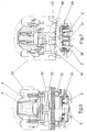
- Fig. 7 shows how the inclination compensation of the mobile crane is brought about.
- the purpose is the chassis frame part which receives the pivot bearing of the basic boom 8 27 with the chassis frame part 28 receiving the wheel sets the piston-cylinder units 29 connected.
- the first-mentioned frame part 27 is how seen in Figure 3, at both ends with downward, cranked Provide pins 30 which are arranged in a directly above the level of the track 3 three-dimensional abutment 31 are supported.
- hydraulic cylinder 33 Fig. 3
- the chassis frame part 27 mounted bolt 34 pulled out of the chassis frame 28 and thus the lock the driving position solved.
- the chassis frame part 27 can make sense in relation to the chassis frame part 28 are inclined transversely to the vehicle longitudinal direction, so that at an angle to the Rails 3 overlying rigid axle drives 2 horizontal alignment of the Pivotal mounting of the base boom receiving chassis frame part 27 allows becomes. In this way, the extendable rails 19 with the entire support stay horizontal even when the chassis is tilted, with the low-lying abutment point of the pin 30 being particularly favorable is.
- each slide 18 is via groove connections 32 clamped on the rails 7 and 19 to lift the carriage vertically Prevent 18 from the rails 7 and 19 even when carrying large loads a tilting moment acts on the carriage 18.
Landscapes
- Engineering & Computer Science (AREA)
- Mechanical Engineering (AREA)
- Jib Cranes (AREA)
Applications Claiming Priority (2)
| Application Number | Priority Date | Filing Date | Title |
|---|---|---|---|
| DE19654521 | 1996-12-19 | ||
| DE19654521A DE19654521C1 (de) | 1996-12-19 | 1996-12-19 | Kran, insbesondere schienengebundener Mobilkran |
Publications (1)
| Publication Number | Publication Date |
|---|---|
| EP0849211A1 true EP0849211A1 (fr) | 1998-06-24 |
Family
ID=7816320
Family Applications (1)
| Application Number | Title | Priority Date | Filing Date |
|---|---|---|---|
| EP97250363A Withdrawn EP0849211A1 (fr) | 1996-12-19 | 1997-11-27 | Grue, en particulier pour voie ferrée |
Country Status (4)
| Country | Link |
|---|---|
| US (1) | US5842589A (fr) |
| EP (1) | EP0849211A1 (fr) |
| JP (1) | JP2947773B2 (fr) |
| DE (1) | DE19654521C1 (fr) |
Cited By (2)
| Publication number | Priority date | Publication date | Assignee | Title |
|---|---|---|---|---|
| CN103738842A (zh) * | 2013-12-16 | 2014-04-23 | 武桥重工集团股份有限公司 | 一种用于支撑高速铁路救援起重机的跨轨台架结构 |
| RU2772085C1 (ru) * | 2021-09-06 | 2022-05-16 | Общество с ограниченной ответственностью «Научно-исследовательский центр СТМ» | Система передачи электрической энергии на траверсу железнодорожного укладочного крана |
Families Citing this family (11)
| Publication number | Priority date | Publication date | Assignee | Title |
|---|---|---|---|---|
| US6024232A (en) * | 1997-07-24 | 2000-02-15 | Kalmar Industries Sverige Ab | Boom truck |
| TW495483B (en) * | 1998-12-25 | 2002-07-21 | Mitsubishi Heavy Ind Ltd | Seismic isolation system for a crane |
| US7308413B1 (en) | 1999-05-05 | 2007-12-11 | Tota Michael J | Process for creating media content based upon submissions received on an electronic multi-media exchange |
| HU222476B1 (hu) * | 1999-10-18 | 2003-07-28 | MIKON Mérnőki, Művészeti és Idegenforgalmi Kft. | Univerzális rakodó konténerek mozgatására |
| AT507333B1 (de) * | 2008-10-09 | 2011-09-15 | Hans Kuenz Ges M B H | Portalkran |
| DE102010024843B4 (de) * | 2010-06-23 | 2012-05-31 | Patrick Kramer | Fahrzeug mit zumindest einem Kran |
| DE102013009357A1 (de) * | 2012-06-11 | 2013-12-12 | Liebherr-Werk Ehingen Gmbh | Modularer Mobilkran |
| CN103523684B (zh) * | 2013-10-28 | 2015-04-15 | 中国矿业大学 | 多起重机协作吊装联接装置及检测方法 |
| CN104925673B (zh) * | 2015-05-21 | 2017-01-04 | 中国矿业大学 | 一种多起重机联合作业辅助起吊装置及方法 |
| CN109573865B (zh) * | 2017-09-29 | 2024-06-07 | 中国铁路总公司 | 一种铁路起重机及其辅助支撑装置 |
| CN115650087B (zh) * | 2022-12-22 | 2023-03-10 | 铭正建设发展有限公司 | 一种建筑材料装卸起重机 |
Citations (7)
| Publication number | Priority date | Publication date | Assignee | Title |
|---|---|---|---|---|
| FR890271A (fr) * | 1942-01-20 | 1944-02-03 | Armin Tenner Fa | Appareil de chargement et de déchargement des wagons couverts |
| CH348252A (de) * | 1956-09-29 | 1960-08-15 | Eberswalde Kranbau | Verlegekran für Gleisstücke |
| FR2023429A1 (fr) * | 1968-11-15 | 1970-08-21 | Pt | |
| GB2139976A (en) * | 1983-04-06 | 1984-11-21 | Takraf Schwermasch | Apparatus to compensate for lateral inclination of vehicles particularly railway cranes |
| EP0665185A1 (fr) * | 1994-01-31 | 1995-08-02 | MANNESMANN Aktiengesellschaft | Grue, en particulier pour voie ferrée |
| DE4402905A1 (de) * | 1994-01-31 | 1995-08-03 | Mannesmann Ag | Kran, insbesondere gleisgebundener Mobilkran |
| EP0727385A2 (fr) * | 1995-02-14 | 1996-08-21 | MANNESMANN Aktiengesellschaft | Grue mobile sur rails |
Family Cites Families (2)
| Publication number | Priority date | Publication date | Assignee | Title |
|---|---|---|---|---|
| DE1280519B (de) * | 1966-05-20 | 1968-10-17 | Otto Kaiser Kommanditgesellsch | Turmdrehkran |
| AT362812B (de) * | 1978-11-16 | 1981-06-25 | Plasser Bahnbaumasch Franz | Fahrbare einrichtung zum aufnehmen und bzw. oder verlegen von gleisweichen oder -kreuzungen |
-
1996
- 1996-12-19 DE DE19654521A patent/DE19654521C1/de not_active Expired - Fee Related
-
1997
- 1997-11-27 EP EP97250363A patent/EP0849211A1/fr not_active Withdrawn
- 1997-12-12 JP JP9362712A patent/JP2947773B2/ja not_active Expired - Fee Related
- 1997-12-18 US US08/992,984 patent/US5842589A/en not_active Expired - Fee Related
Patent Citations (7)
| Publication number | Priority date | Publication date | Assignee | Title |
|---|---|---|---|---|
| FR890271A (fr) * | 1942-01-20 | 1944-02-03 | Armin Tenner Fa | Appareil de chargement et de déchargement des wagons couverts |
| CH348252A (de) * | 1956-09-29 | 1960-08-15 | Eberswalde Kranbau | Verlegekran für Gleisstücke |
| FR2023429A1 (fr) * | 1968-11-15 | 1970-08-21 | Pt | |
| GB2139976A (en) * | 1983-04-06 | 1984-11-21 | Takraf Schwermasch | Apparatus to compensate for lateral inclination of vehicles particularly railway cranes |
| EP0665185A1 (fr) * | 1994-01-31 | 1995-08-02 | MANNESMANN Aktiengesellschaft | Grue, en particulier pour voie ferrée |
| DE4402905A1 (de) * | 1994-01-31 | 1995-08-03 | Mannesmann Ag | Kran, insbesondere gleisgebundener Mobilkran |
| EP0727385A2 (fr) * | 1995-02-14 | 1996-08-21 | MANNESMANN Aktiengesellschaft | Grue mobile sur rails |
Cited By (2)
| Publication number | Priority date | Publication date | Assignee | Title |
|---|---|---|---|---|
| CN103738842A (zh) * | 2013-12-16 | 2014-04-23 | 武桥重工集团股份有限公司 | 一种用于支撑高速铁路救援起重机的跨轨台架结构 |
| RU2772085C1 (ru) * | 2021-09-06 | 2022-05-16 | Общество с ограниченной ответственностью «Научно-исследовательский центр СТМ» | Система передачи электрической энергии на траверсу железнодорожного укладочного крана |
Also Published As
| Publication number | Publication date |
|---|---|
| JPH10182071A (ja) | 1998-07-07 |
| DE19654521C1 (de) | 1998-06-18 |
| US5842589A (en) | 1998-12-01 |
| JP2947773B2 (ja) | 1999-09-13 |
Similar Documents
| Publication | Publication Date | Title |
|---|---|---|
| EP0156304B1 (fr) | Dispositif pour l'inspection des parties inférieures des ponts | |
| EP0682148B1 (fr) | Appareillage pour le transport des tronçons assemblés de la voie | |
| DE1944214B2 (de) | Chienenlos verfahrbarer drehkranunterwagen | |
| EP0989087A1 (fr) | Grue, de préference grue Derrick | |
| DE19654521C1 (de) | Kran, insbesondere schienengebundener Mobilkran | |
| EP1157959B1 (fr) | Grue mobile de port pour le transfer combiné de containers et de matière en vrac | |
| EP0669278B1 (fr) | Grue, en particulier grue mobile sur rails | |
| EP0665185B1 (fr) | Grue, en particulier pour voie ferrée | |
| EP0486456B1 (fr) | Wagon pour le transport d'aiguillage ferroviaire | |
| EP0464062B1 (fr) | Dispositif d'inspection du cote inferieur de ponts | |
| EP0285698A1 (fr) | Véhicule utilitaire avec conteneur interchangeable | |
| DE2834163A1 (de) | Eisenbahnfahrzeug zum umsetzen von behaeltern wie containern auf seitlich des fahrzeuges befindlichen abstellflaechen | |
| DE1658328A1 (de) | Geraet fuer das Hantieren mit Gleiseinbauten | |
| EP0433935B1 (fr) | Véhicule ferroviaire motorisé avec nacelle mobile | |
| EP0881190B1 (fr) | Grue mobile pour voie ferrée avec wagon auxiliaire accouplée | |
| DE2228196B2 (de) | Einrichtung zum Auswechseln von Gleisjochen | |
| DE2450003C2 (de) | Fahrzeugkran mit Kabine mit verschiedenen Stellungen | |
| DE3706693A1 (de) | Auf schienen verfahrbarer umbauwagen fuer gleisanlagen | |
| DE3020770C2 (de) | Fahrzeug für den Ausbau von Gruben und Tunnelbauten | |
| EP1395510A1 (fr) | Chariot de manutention | |
| AT524598A2 (de) | Fahrzeugkran mit einem wippbaren Hauptausleger und mit einem Zusatzauslegersystem | |
| DE3431561A1 (de) | Nutzfahrzeug mit kombinierter verladeeinrichtung | |
| DE2742461C2 (de) | Eisenbahnfahrzeug zum Umsetzen von Behältern, wie Containern | |
| DE3046570A1 (de) | Verfahren zum ueberfuehren von strebausbaugestellen von einer grundstrecke in einen streb bzw. aus einem streb in die grundstrecke sowie vorrichtungen zur durchfuehrung eines solchen verfahrens | |
| DE3043786A1 (de) | Fahrzeug fuer den transport von vorgefertigten raumzellen, insbesondere aus beton, z.b. fertiggaragen |
Legal Events
| Date | Code | Title | Description |
|---|---|---|---|
| PUAI | Public reference made under article 153(3) epc to a published international application that has entered the european phase |
Free format text: ORIGINAL CODE: 0009012 |
|
| 17P | Request for examination filed |
Effective date: 19980427 |
|
| AK | Designated contracting states |
Kind code of ref document: A1 Designated state(s): AT BE CH DE DK ES FR GB GR IE IT LI NL PT SE |
|
| AX | Request for extension of the european patent |
Free format text: AL;LT;LV;MK;RO;SI |
|
| AKX | Designation fees paid |
Free format text: AT BE CH DE DK ES FR GB GR IE IT LI NL PT SE |
|
| RBV | Designated contracting states (corrected) |
Designated state(s): AT BE CH DE DK ES FR GB GR IE IT LI NL PT SE |
|
| GRAG | Despatch of communication of intention to grant |
Free format text: ORIGINAL CODE: EPIDOS AGRA |
|
| 17Q | First examination report despatched |
Effective date: 20011122 |
|
| GRAG | Despatch of communication of intention to grant |
Free format text: ORIGINAL CODE: EPIDOS AGRA |
|
| GRAH | Despatch of communication of intention to grant a patent |
Free format text: ORIGINAL CODE: EPIDOS IGRA |
|
| RAP1 | Party data changed (applicant data changed or rights of an application transferred) |
Owner name: DEMAG MOBILE CRANES GMBH |
|
| STAA | Information on the status of an ep patent application or granted ep patent |
Free format text: STATUS: THE APPLICATION HAS BEEN WITHDRAWN |
|
| 18W | Application withdrawn |
Withdrawal date: 20020429 |