EP0849656A2 - Bouton-poussoir coulissant par pression - Google Patents
Bouton-poussoir coulissant par pression Download PDFInfo
- Publication number
- EP0849656A2 EP0849656A2 EP97121383A EP97121383A EP0849656A2 EP 0849656 A2 EP0849656 A2 EP 0849656A2 EP 97121383 A EP97121383 A EP 97121383A EP 97121383 A EP97121383 A EP 97121383A EP 0849656 A2 EP0849656 A2 EP 0849656A2
- Authority
- EP
- European Patent Office
- Prior art keywords
- sliding surface
- push button
- sliding
- pressed
- partition
- Prior art date
- Legal status (The legal status is an assumption and is not a legal conclusion. Google has not performed a legal analysis and makes no representation as to the accuracy of the status listed.)
- Granted
Links
Images


Classifications
-
- H—ELECTRICITY
- H01—ELECTRIC ELEMENTS
- H01H—ELECTRIC SWITCHES; RELAYS; SELECTORS; EMERGENCY PROTECTIVE DEVICES
- H01H13/00—Switches having rectilinearly-movable operating part or parts adapted for pushing or pulling in one direction only, e.g. push-button switch
- H01H13/50—Switches having rectilinearly-movable operating part or parts adapted for pushing or pulling in one direction only, e.g. push-button switch having a single operating member
- H01H13/56—Switches having rectilinearly-movable operating part or parts adapted for pushing or pulling in one direction only, e.g. push-button switch having a single operating member the contact returning to its original state upon the next application of operating force
- H01H13/562—Switches having rectilinearly-movable operating part or parts adapted for pushing or pulling in one direction only, e.g. push-button switch having a single operating member the contact returning to its original state upon the next application of operating force making use of a heart shaped cam
-
- G—PHYSICS
- G05—CONTROLLING; REGULATING
- G05G—CONTROL DEVICES OR SYSTEMS INSOFAR AS CHARACTERISED BY MECHANICAL FEATURES ONLY
- G05G1/00—Controlling members, e.g. knobs or handles; Assemblies or arrangements thereof; Indicating position of controlling members
- G05G1/08—Controlling members for hand actuation by rotary movement, e.g. hand wheels
-
- H—ELECTRICITY
- H01—ELECTRIC ELEMENTS
- H01H—ELECTRIC SWITCHES; RELAYS; SELECTORS; EMERGENCY PROTECTIVE DEVICES
- H01H13/00—Switches having rectilinearly-movable operating part or parts adapted for pushing or pulling in one direction only, e.g. push-button switch
- H01H13/50—Switches having rectilinearly-movable operating part or parts adapted for pushing or pulling in one direction only, e.g. push-button switch having a single operating member
- H01H13/56—Switches having rectilinearly-movable operating part or parts adapted for pushing or pulling in one direction only, e.g. push-button switch having a single operating member the contact returning to its original state upon the next application of operating force
- H01H13/562—Switches having rectilinearly-movable operating part or parts adapted for pushing or pulling in one direction only, e.g. push-button switch having a single operating member the contact returning to its original state upon the next application of operating force making use of a heart shaped cam
- H01H13/568—Switches having rectilinearly-movable operating part or parts adapted for pushing or pulling in one direction only, e.g. push-button switch having a single operating member the contact returning to its original state upon the next application of operating force making use of a heart shaped cam the contact also returning by some external action, e.g. interlocking, protection, remote control
Definitions
- the invention relates to a linear by manual pressing against the force of a spring from a first stable position to a second stable position (pressed position) and under the force of the spring push button which can be pushed back to actuate one or several components according to the preamble of claim 1.
- Linear push buttons are known, for example, in ballpoint pens become. There are two displaceable and rotatable against each other Advancing elements inside the ballpoint pen cylinder, which interlock and have contacting radial surfaces with a kind of spur toothing, so that when one part is twisted against the other, the one part, which picks up the ballpoint pen refill, is moved back and forth.
- a push button of the type mentioned is known from FR 2 322 442.
- the object of the invention is to design a push button of the type mentioned at the beginning, that a correct movement of the locking element around the partition always is ensured and that there is sufficient robustness of the push button is achieved.
- the second sliding surface is increased at least in the connection section facing away from the pressing surface to the first sliding surface with respect to this by the third step.
- first sliding surface there is between the first sliding surface and the sliding surface section, which lies in the area of the rest bag, with a first step which is safely achieved that when the locking element is in the locking bag, when depressed, the locking element can not move into the first sliding surface.
- a second step is provided, via which the adjacent to the rest bag Sliding surface section drops to the second sliding surface; this also makes it safe achieved that the locking element does not come back into the area of the locking bag can when the push button is pressed.
- a total of three steps can therefore be provided, via which the locking element in a circulation around the partition wall from the one sliding surface in the each adjacent sliding surface section can fall in, thereby ensuring is that the locking element always moves in the same direction around the partition.
- the locking element has one Latch holding lever with a nose running perpendicular to it, which around an axis, the runs perpendicular to the plane of the sliding surface, is pivotable, whereby that the nose can also run safely around the partition when pressed.
- a first spring is provided to keep the nose on the sliding surfaces Locking lever constantly pushes towards sliding surfaces.
- a second spring provided the locking lever around the axis perpendicular to the sliding surface element runs, acted in one direction, so that a revolution of the nose on the sliding surfaces around the partition is ensured in any case.
- the latching lever is on a rotatably mounted Shaped retaining pin, which is slidably movable in its own axis and on which the spring acts so that the nose is pressed against the sliding surfaces.
- the path of movement of the holding pin so dimensioned that the nose of the Sliding surfaces can be pressed off via the partition.
- the latter solution is used when the push button as Actuator used in a line or residual current circuit breaker should find. Then namely the locking lever or the locking lug in the case of a Overcurrent or a short-circuit current or a fault current are moved so that she doesn't get into the rest bag; with a correspondingly constructive Embodiment, the locking lever or the holding pin of a contact lever be moved so that the nose can slide over the partition, what is caused by the second spring.
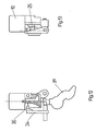
- a push button 10 of FIG. 1 comprises a cylindrical section 11, the invisible surface (at 12) in the drawing having a pressing surface.
- a first projection 14 and a second projection 15 adjoin the opposite circular surface 13 of the cylindrical section, which projection has an approximately rectangular shape and on which a sliding surface arrangement 16 is provided on one of the broad sides.
- the sliding surface arrangement 16 has a first sliding surface 17 which runs approximately parallel to the direction of movement of the push button 10 and a second sliding surface 18 which runs parallel to it and is connected to one another in its area on the pressure surface side via a connection point 19 and also via a connection point 20 away from the pressure surface.
- the two sliding surfaces 17 and 18 From a reference plane, not shown, which runs parallel to the sliding surfaces or approximately parallel to the sliding surfaces 17, 18, the two sliding surfaces 17 and 18 have different distances: the first sliding surface rises slightly from the connection point 20 to one in the area of the connection point 19 located saddle surface 21, which drops to the actual connection point 19 via a step 22. Via a further step 23, the connection point 19 drops to the second sliding surface 18, which rises up to the connection point 20 with respect to this reference plane, so that a third step 24 is provided at the connection point 20 between the second sliding surface and the first sliding surface the second sliding surface drops to the first sliding surface 17. Between the sliding surfaces 16 and 17 there is a dividing wall 25, which is provided with a latching bag 26 on the connection point 19, that is to say the connection point 19 close to the pressing surface.
- connection point 19 of the two sliding surfaces 17 and 18 is thus closed at the top towards the pressure surface side by a step 27 running perpendicular to it, which extends at an angle of 45 ° to the direction of movement of the push button and merges into step 22, the step 27 or Boundary wall 27 runs parallel to the V surface 28 of the rest bag 26 adjacent to the slideway 18.
- the locking lug moves in the direction of the arrow P 2 and is deflected via the step 27 and the further step 23 towards the second sliding surface 18 and then slides on the second sliding surface when the push button slides up again 18 to the second connection point 20 and snaps back onto the first slideway 17 via the step 24.
- the latching nose is thus guided through the partition 25, the step 27 and a boundary wall 29 running parallel to the partition 25, between which the second sliding surface 18 runs.
- the boundary wall 29 has in the region of the connection point 20 an arc 30 inclined towards the sliding surface 17.
- the locking lug is guided between the boundary wall 29 with the arch 30 and the partition wall 25 on the sliding surface 18.
- the locking element thus makes a movement perpendicular to the reference plane and also a rotation about an axis of rotation that is perpendicular runs to the reference plane. So that this rotary movement is ensured in every case a second spring is provided, the spring force of which counteracts the latching element turns clockwise or acted on, so that the latch 34 on the Partition 25 along on the sliding surface 17 to the rest bag 26 and from there along the boundary wall 29 slides to the starting point at the connection point 20 (see also Fig. 3).
- the push button 10 pushes up.
- the indentation movement is the movement in the direction of arrow E and the push-out movement is the movement in the direction of arrow A.
- the movement E takes place manually and the movement A due to the located in the bore 33 Compression spring.
- FIGS. 2 and 3 show the push button 10 with the sliding surface 17 on which the sliding element 34 or locking element 34 slides along.
- This locking element 34 has one Nose 35, which is approximately parallel to the direction of movement of the push button 10 extending arm 36 is integrally formed with a transverse bolt 37th connected is; the bolt 37 is displaceable in its axial direction, so that the Arm 36 is slidable; in addition, the bolt 37 is also rotatable about its Longitudinal axis, so that the arm 36 is pivotable about the pin axis 37.
- FIG. 3 shows the locking arm 36 with the locking lug 34 at the second connection point 20. If the push button is pressed in the direction of arrow E, then slides, as in FIG. 5 can be seen, the locking lug of the locking arm 36 towards the connection point 19 and then, as can be seen from FIGS. 7, 8 and 9, snaps into the rest bag 26; 8 and 9 show this pressed-in, stable position.
- FIGS. 2 and 3 show the arrangements in the off position, so if the Push button 10 completely protrudes from the switching device.
- the latch 35 is located itself at the junction 20.
- the movable contact piece is in its OFF position.
- push button 10 is pressed in the direction of arrow E, whereby via a switch lock arrangement, not shown in the figures, with is connected to the push button, the movable contact lever 39 in the contact position arrives with a fixed contact piece 41.
- the locking element 35 is located on the sliding surface 17 but still at a certain distance from the connection point 19. If the push button 10 is pushed in further, the latch 35 becomes in the area snap the connection point 19 into the rest bag 26; one can see in Fig.
- the locking element must in the case a short-circuit current are moved so that it is in the depressed state of the Push button can not get into the rest bag 26; here it is from the contact lever 39 moved to the left over the projection 41 and thus slides over the partition, see Fig. 12 and 13.
- the second spring which acts as a torsion spring with a rotational force F on the locking element exercises essential.
Landscapes
- Physics & Mathematics (AREA)
- General Physics & Mathematics (AREA)
- Engineering & Computer Science (AREA)
- Automation & Control Theory (AREA)
- Breakers (AREA)
- Bearings For Parts Moving Linearly (AREA)
- Switch Cases, Indication, And Locking (AREA)
- Push-Button Switches (AREA)
Applications Claiming Priority (2)
| Application Number | Priority Date | Filing Date | Title |
|---|---|---|---|
| DE19653380 | 1996-12-20 | ||
| DE19653380A DE19653380A1 (de) | 1996-12-20 | 1996-12-20 | Linear durch Drücken verschiebbarer Druckknopf zur Betätigung eines oder mehrerer Bauelemente |
Publications (3)
| Publication Number | Publication Date |
|---|---|
| EP0849656A2 true EP0849656A2 (fr) | 1998-06-24 |
| EP0849656A3 EP0849656A3 (fr) | 2003-10-29 |
| EP0849656B1 EP0849656B1 (fr) | 2005-04-27 |
Family
ID=7815600
Family Applications (1)
| Application Number | Title | Priority Date | Filing Date |
|---|---|---|---|
| EP97121383A Expired - Lifetime EP0849656B1 (fr) | 1996-12-20 | 1997-12-05 | Bouton-poussoir coulissant par pression |
Country Status (2)
| Country | Link |
|---|---|
| EP (1) | EP0849656B1 (fr) |
| DE (2) | DE19653380A1 (fr) |
Families Citing this family (2)
| Publication number | Priority date | Publication date | Assignee | Title |
|---|---|---|---|---|
| DE102008030096A1 (de) * | 2008-06-25 | 2009-12-31 | Fischer Automotive Systems Gmbh & Co. Kg | Schließmechanismus |
| CN110962490B (zh) * | 2019-12-22 | 2020-10-09 | 杭州简弈科技有限公司 | 一种按压自锁结构以及采用该结构的按压笔 |
Citations (1)
| Publication number | Priority date | Publication date | Assignee | Title |
|---|---|---|---|---|
| FR2322442A1 (fr) | 1975-08-29 | 1977-03-25 | Tschudin & Heid Ag | Interrupteur a bouton-poussoir |
Family Cites Families (8)
| Publication number | Priority date | Publication date | Assignee | Title |
|---|---|---|---|---|
| FR1285260A (fr) * | 1960-11-21 | 1962-02-23 | Socapex | Dispositif commutateur |
| DE1294263B (de) * | 1962-02-23 | 1969-04-30 | Bross | Schaltmechanik, insbesondere fuer Kugelschreiber |
| DE2417330A1 (de) * | 1974-04-09 | 1975-11-06 | Mecanismos Aux Ind | Umschalter |
| DE3419834A1 (de) * | 1984-05-26 | 1985-11-28 | SWF Auto-Electric GmbH, 7120 Bietigheim-Bissingen | Elektrischer drucktastenschalter |
| DE3446429A1 (de) * | 1984-12-20 | 1986-06-26 | Kernforschungszentrum Karlsruhe Gmbh, 7500 Karlsruhe | Vorrichtung zum gegenseitigen verriegeln zweier ineinander- oder nebeneinanderliegender, senkrecht oder schraeg stehender bauelemente |
| JPH0633621Y2 (ja) * | 1985-11-21 | 1994-08-31 | アルプス電気株式会社 | プツシユロツク装置 |
| DE4243991C2 (de) * | 1992-12-23 | 1998-05-07 | Bosch Siemens Hausgeraete | Schalterbetätigungsvorrichtung |
| DE4343976C2 (de) * | 1993-12-22 | 1998-02-12 | Bosch Siemens Hausgeraete | Versenkbar angeordneter Türgriff |
-
1996
- 1996-12-20 DE DE19653380A patent/DE19653380A1/de not_active Ceased
-
1997
- 1997-12-05 DE DE59712284T patent/DE59712284D1/de not_active Expired - Lifetime
- 1997-12-05 EP EP97121383A patent/EP0849656B1/fr not_active Expired - Lifetime
Patent Citations (1)
| Publication number | Priority date | Publication date | Assignee | Title |
|---|---|---|---|---|
| FR2322442A1 (fr) | 1975-08-29 | 1977-03-25 | Tschudin & Heid Ag | Interrupteur a bouton-poussoir |
Also Published As
| Publication number | Publication date |
|---|---|
| EP0849656A3 (fr) | 2003-10-29 |
| DE19653380A1 (de) | 1998-06-25 |
| EP0849656B1 (fr) | 2005-04-27 |
| DE59712284D1 (de) | 2005-06-02 |
Similar Documents
| Publication | Publication Date | Title |
|---|---|---|
| EP0295437B1 (fr) | Dispositif de bouton-poussoirs | |
| EP3316422A1 (fr) | Adaptateur électrique de voyage facile à utiliser | |
| WO2017207096A1 (fr) | Prise de voyage compacte | |
| DE202020105715U1 (de) | Klemme mit Lösehebel | |
| DE19726149C2 (de) | Schalteranordnung | |
| EP0673095A1 (fr) | Commutateur électrique | |
| DE2737517A1 (de) | Elektrischer schalter | |
| DE102005043903B3 (de) | Stecker | |
| DE2904899C2 (de) | Elektrischer Schalter | |
| EP0849656B1 (fr) | Bouton-poussoir coulissant par pression | |
| DE4229756A1 (de) | Elektrisches Schaltgerät | |
| DE4433617A1 (de) | Elektrisches Steckverbindungsteil | |
| DE2643955A1 (de) | Elektrischer schnappschalter | |
| EP0068483B1 (fr) | Commutateur électromécanique pour appareils téléphoniques | |
| DE19507605C1 (de) | Verklinkungseinrichtung für elektrische Schalter | |
| WO2000024022A1 (fr) | Dispositif de couplage | |
| DE2904646C2 (de) | Drucktastenschalter | |
| EP3208889B1 (fr) | Bloc de jonction à ressort de traction | |
| DE4211915C2 (de) | Prüftastenanordnung für einen Fehlerstrom- oder Differenzstromschutzschalter | |
| EP0565009A1 (fr) | Appareil d'installation | |
| EP1069583A2 (fr) | Mécanisme de commutation pour appareillage électrique de commutation, en particulier pour un disjoncteur | |
| DE10054170C2 (de) | Sicherungsleiste | |
| DE29714134U1 (de) | Verriegelungsschieber für Sicherung | |
| DE29714133U1 (de) | Sicherung mit Berührungsschutzschieber | |
| DE102023208353A1 (de) | Schutzschaltgerät mit Drucktaste |
Legal Events
| Date | Code | Title | Description |
|---|---|---|---|
| PUAI | Public reference made under article 153(3) epc to a published international application that has entered the european phase |
Free format text: ORIGINAL CODE: 0009012 |
|
| AK | Designated contracting states |
Kind code of ref document: A2 Designated state(s): AT BE CH DE DK ES FI FR GB GR IE IT LI LU MC NL PT SE |
|
| AX | Request for extension of the european patent |
Free format text: AL;LT;LV;MK;RO;SI |
|
| RAP1 | Party data changed (applicant data changed or rights of an application transferred) |
Owner name: ABB PATENT GMBH |
|
| PUAL | Search report despatched |
Free format text: ORIGINAL CODE: 0009013 |
|
| AK | Designated contracting states |
Kind code of ref document: A3 Designated state(s): AT BE CH DE DK ES FI FR GB GR IE IT LI LU MC NL PT SE |
|
| AX | Request for extension of the european patent |
Extension state: AL LT LV MK RO SI |
|
| RIC1 | Information provided on ipc code assigned before grant |
Ipc: 7G 05G 1/02 B Ipc: 7H 01H 11/00 B Ipc: 7G 05G 1/08 A |
|
| 17P | Request for examination filed |
Effective date: 20031201 |
|
| AKX | Designation fees paid |
Designated state(s): DE FR GB IT |
|
| 17Q | First examination report despatched |
Effective date: 20040302 |
|
| GRAP | Despatch of communication of intention to grant a patent |
Free format text: ORIGINAL CODE: EPIDOSNIGR1 |
|
| GRAS | Grant fee paid |
Free format text: ORIGINAL CODE: EPIDOSNIGR3 |
|
| GRAA | (expected) grant |
Free format text: ORIGINAL CODE: 0009210 |
|
| AK | Designated contracting states |
Kind code of ref document: B1 Designated state(s): DE FR GB IT |
|
| REG | Reference to a national code |
Ref country code: GB Ref legal event code: FG4D Free format text: NOT ENGLISH |
|
| GBT | Gb: translation of ep patent filed (gb section 77(6)(a)/1977) |
Effective date: 20050427 |
|
| REG | Reference to a national code |
Ref country code: IE Ref legal event code: FG4D Free format text: LANGUAGE OF EP DOCUMENT: GERMAN |
|
| REF | Corresponds to: |
Ref document number: 59712284 Country of ref document: DE Date of ref document: 20050602 Kind code of ref document: P |
|
| RBV | Designated contracting states (corrected) |
Designated state(s): DE FR GB IT |
|
| ET | Fr: translation filed | ||
| PLBE | No opposition filed within time limit |
Free format text: ORIGINAL CODE: 0009261 |
|
| STAA | Information on the status of an ep patent application or granted ep patent |
Free format text: STATUS: NO OPPOSITION FILED WITHIN TIME LIMIT |
|
| 26N | No opposition filed |
Effective date: 20060130 |
|
| PGFP | Annual fee paid to national office [announced via postgrant information from national office to epo] |
Ref country code: GB Payment date: 20061221 Year of fee payment: 10 |
|
| PGFP | Annual fee paid to national office [announced via postgrant information from national office to epo] |
Ref country code: IT Payment date: 20061231 Year of fee payment: 10 |
|
| PGFP | Annual fee paid to national office [announced via postgrant information from national office to epo] |
Ref country code: FR Payment date: 20061212 Year of fee payment: 10 |
|
| GBPC | Gb: european patent ceased through non-payment of renewal fee |
Effective date: 20071205 |
|
| REG | Reference to a national code |
Ref country code: FR Ref legal event code: ST Effective date: 20081020 |
|
| PG25 | Lapsed in a contracting state [announced via postgrant information from national office to epo] |
Ref country code: GB Free format text: LAPSE BECAUSE OF NON-PAYMENT OF DUE FEES Effective date: 20071205 |
|
| PG25 | Lapsed in a contracting state [announced via postgrant information from national office to epo] |
Ref country code: FR Free format text: LAPSE BECAUSE OF NON-PAYMENT OF DUE FEES Effective date: 20071231 |
|
| PG25 | Lapsed in a contracting state [announced via postgrant information from national office to epo] |
Ref country code: IT Free format text: LAPSE BECAUSE OF NON-PAYMENT OF DUE FEES Effective date: 20071205 |
|
| PGFP | Annual fee paid to national office [announced via postgrant information from national office to epo] |
Ref country code: DE Payment date: 20101222 Year of fee payment: 14 |
|
| REG | Reference to a national code |
Ref country code: DE Ref legal event code: R119 Ref document number: 59712284 Country of ref document: DE Effective date: 20120703 |
|
| PG25 | Lapsed in a contracting state [announced via postgrant information from national office to epo] |
Ref country code: DE Free format text: LAPSE BECAUSE OF NON-PAYMENT OF DUE FEES Effective date: 20120703 |