EP0849754A2 - Relais électromagnétique - Google Patents
Relais électromagnétique Download PDFInfo
- Publication number
- EP0849754A2 EP0849754A2 EP97116035A EP97116035A EP0849754A2 EP 0849754 A2 EP0849754 A2 EP 0849754A2 EP 97116035 A EP97116035 A EP 97116035A EP 97116035 A EP97116035 A EP 97116035A EP 0849754 A2 EP0849754 A2 EP 0849754A2
- Authority
- EP
- European Patent Office
- Prior art keywords
- coil
- armature
- relay according
- switching spring
- relay
- Prior art date
- Legal status (The legal status is an assumption and is not a legal conclusion. Google has not performed a legal analysis and makes no representation as to the accuracy of the status listed.)
- Withdrawn
Links
- 238000004804 winding Methods 0.000 claims abstract description 9
- 230000013011 mating Effects 0.000 claims abstract description 7
- 229910010293 ceramic material Inorganic materials 0.000 claims description 5
- 238000005452 bending Methods 0.000 claims description 4
- 230000002093 peripheral effect Effects 0.000 claims description 4
- 239000004033 plastic Substances 0.000 claims description 4
- 239000000919 ceramic Substances 0.000 abstract description 8
- 239000000463 material Substances 0.000 abstract description 7
- 206010001497 Agitation Diseases 0.000 description 1
- RYGMFSIKBFXOCR-UHFFFAOYSA-N Copper Chemical compound [Cu] RYGMFSIKBFXOCR-UHFFFAOYSA-N 0.000 description 1
- 208000000260 Warts Diseases 0.000 description 1
- 238000005219 brazing Methods 0.000 description 1
- 239000000969 carrier Substances 0.000 description 1
- 238000005266 casting Methods 0.000 description 1
- 238000010276 construction Methods 0.000 description 1
- 229910052802 copper Inorganic materials 0.000 description 1
- 239000010949 copper Substances 0.000 description 1
- 230000003628 erosive effect Effects 0.000 description 1
- 239000000945 filler Substances 0.000 description 1
- 239000011521 glass Substances 0.000 description 1
- 238000010438 heat treatment Methods 0.000 description 1
- 238000001746 injection moulding Methods 0.000 description 1
- 229910052500 inorganic mineral Inorganic materials 0.000 description 1
- 238000002955 isolation Methods 0.000 description 1
- 238000003754 machining Methods 0.000 description 1
- 239000002184 metal Substances 0.000 description 1
- 229910052751 metal Inorganic materials 0.000 description 1
- 239000011707 mineral Substances 0.000 description 1
- 210000002445 nipple Anatomy 0.000 description 1
- 239000000843 powder Substances 0.000 description 1
- 201000010153 skin papilloma Diseases 0.000 description 1
- 238000005476 soldering Methods 0.000 description 1
- 229920001169 thermoplastic Polymers 0.000 description 1
- 239000004416 thermosoftening plastic Substances 0.000 description 1
Images

Classifications
-
- H—ELECTRICITY
- H01—ELECTRIC ELEMENTS
- H01H—ELECTRIC SWITCHES; RELAYS; SELECTORS; EMERGENCY PROTECTIVE DEVICES
- H01H50/00—Details of electromagnetic relays
- H01H50/54—Contact arrangements
- H01H50/56—Contact spring sets
-
- H—ELECTRICITY
- H01—ELECTRIC ELEMENTS
- H01H—ELECTRIC SWITCHES; RELAYS; SELECTORS; EMERGENCY PROTECTIVE DEVICES
- H01H50/00—Details of electromagnetic relays
- H01H50/16—Magnetic circuit arrangements
- H01H50/18—Movable parts of magnetic circuits, e.g. armature
-
- H—ELECTRICITY
- H01—ELECTRIC ELEMENTS
- H01H—ELECTRIC SWITCHES; RELAYS; SELECTORS; EMERGENCY PROTECTIVE DEVICES
- H01H1/00—Contacts
- H01H1/58—Electric connections to or between contacts; Terminals
- H01H2001/5888—Terminals of surface mounted devices [SMD]
-
- H—ELECTRICITY
- H01—ELECTRIC ELEMENTS
- H01H—ELECTRIC SWITCHES; RELAYS; SELECTORS; EMERGENCY PROTECTIVE DEVICES
- H01H50/00—Details of electromagnetic relays
- H01H50/16—Magnetic circuit arrangements
- H01H50/36—Stationary parts of magnetic circuit, e.g. yoke
-
- H—ELECTRICITY
- H01—ELECTRIC ELEMENTS
- H01H—ELECTRIC SWITCHES; RELAYS; SELECTORS; EMERGENCY PROTECTIVE DEVICES
- H01H50/00—Details of electromagnetic relays
- H01H50/44—Magnetic coils or windings
Definitions
- Such a simply constructed relay with a base body serving bobbin, a U-shaped core yoke and one plate-shaped anchor is for example from the document WO 90/09028 known.
- the switch spring is there directly with connected to the anchor and also via an angled section welded to the yoke. So it serves both as an anchor bearing spring as well as an electrical connection for the mobile Contacts.
- the cross sections for the load circuit be oversized to reduce the power dissipation hold, also the coil for a small power dissipation can be designed with a high winding wire volume.
- the contact and required in the conventional structure The armature return spring must be made of a material with low relaxation behavior at high temperatures, i.e. for example made of an expensive beryllium-alloyed copper spring material be executed. These parameters physically limit the Miniaturization of electromechanical relays for large loads at high ambient temperature.
- the aim of the present invention is to provide a relay of the input mentioned type with the simplest possible structure and to produce as few individual parts as possible, the individual parts have a simple shape and with as little processing as possible can be joined together, so that inexpensive Materials can be used and still that Volume can be kept small depending on the application.
- the relay is intended in particular for applications with high thermal loads be suitable.
- this goal is at the beginning of a relay mentioned type achieved in that the switching spring in attached to a peripheral region of the first coil flange is between the end sections of the core leg and of the yoke leg extends through, the anchor in an approximately parallel plane to it, and that the Switch spring in an opposite to the fastening point peripheral area of the coil flange one with the mating contact elements cooperating contact bridge carries.
- the switching spring therefore needs not to conduct a load current itself, since this only via the Bridge contact flows at its end. She doesn't need one either It must therefore also take over the bearing function for the anchor not to be bent and can therefore be proportionate stiff material in the simplest form without subsequent Machining.
- the spring can in principle also be made of metal; with regard a low relaxation behavior at high thermal loads and desirable isolation between the load circuit and magnetic circuit come high temperature resistant for the spring Plastic materials, but preferably a ceramic material, into consideration.
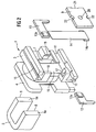
- the relay shown in the drawing has a coil former 1 made of ceramic material, which also serves as the main body and supports for the functional elements.
- a coil winding 2 is applied; she will limited by a first flange 3 and a second flange 4.
- a U-shaped core yoke 5 is with a core leg 6 inserted through an axial opening 7 of the bobbin 1, while a yoke leg 8 is parallel to it next to the coil extends.
- the coil former 1 is made of ceramic material and is preferably produced by powder injection molding. To the second flange 4 are also two coil connections 1a directly integrally formed so that they with the winding ends 2a Coil 2 can be wrapped directly. This allows the temperature-resistant Coil body 1 directly in a circuit board be soldered in.
- first coil flange 3 In the first coil flange 3 are near the bottom two drawer-like shafts 10 and 11 molded into the two mating contact carriers 12 from opposite sides and 13 are inserted with counter contacts 12a and 13a. Furthermore is a ceramic spring as switching spring 14 of simpler rectangular shape provided with one end in the top Area of the first coil flange 3 in a formed there Slot 15 is fixed.
- the attachment can, for example by soldering, by casting or by means of ceramic putty be made.
- Switch spring 14 At the other end she wears Switch spring 14 is a transverse contact band, which as Bridge contact 14a with the two fixed mating contacts 12a and 13a cooperate, so when tightening the Anchor bridges.
- the bridge contact 14a can be soldered with the pre-galvanized switching spring in this area 14 are connected.
- the flat switching spring 14 is so outward standing obliquely clamped that they have a bias to Anchor experiences and the required restoring force delivers.
- the armature 9 is in a free recess 16 of the bobbin flange 2 freely movable and by stops and retaining tabs 17, 18 and 19 cannot be lost on all sides secured. In the middle it has a spherical pressure wart 20 with which he is at 90 ° to the longitudinal extension of the armature rotated switching spring actuated. At The example shown is the force of the magnet system approximately with a gear ratio of 2: 1 to the bridge contact 14a transmitted. When the armature is not excited 9, the spring 14 presses the armature against the stop lugs 17, 18 and 19.
- the assembly of the armature 9 is carried out according to the schematic representation in Figure 5 in such a way that it is initially V-shaped is angled (state 9-1); is in this state Length lx of the anchor in the area of a lateral recess 21 so shortened that lx is less than the length l1 which the Opening length of the recess 16 designated on the retaining lug 19.
- the anchor can be in the state 9-1 on the retaining lug 19 are inserted into the recess 16. After that the anchor by attacking a force F from the back the actuating nipple 20 along one through constrictions 22 formed predetermined bending point deformed until it is approximately flat and has the length l2. With this length l2 it is captive behind the retaining lugs 17, 18 and 19
- the time can of closing the contacts can be detected so that by a defined overpressure the required overstroke as contact erosion safety can be adjusted.
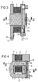
- Figures 3 and 4 are sections III-III and IV-IV in Longitudinal and transverse directions are shown.
- the relay can operate at higher temperatures be operated with a low-resistance coil; it can be compared to conventional relays at higher temperatures also smaller cross sections for the electrical Load circuit and the magnetic circuit are used, which means less Material is consumed. So that it can also be exposed Places with high ambient temperatures are used.
- the bobbin is also a bobbin from a highly filled thermoplastic, for example with mineral, ceramic or glass fillers.
- the relay can also be equipped with SMD connections if required be provided.
- the contact arrangement can also instead of the bridge closer shown, a bridge opener or form a bridge changer.
Landscapes
- Physics & Mathematics (AREA)
- Electromagnetism (AREA)
- Electromagnets (AREA)
- Cookers (AREA)
- Surgical Instruments (AREA)
- Valve Device For Special Equipments (AREA)
Applications Claiming Priority (2)
| Application Number | Priority Date | Filing Date | Title |
|---|---|---|---|
| DE29622093U | 1996-12-19 | ||
| DE29622093U DE29622093U1 (de) | 1996-12-19 | 1996-12-19 | Elektromagnetisches Relais |
Publications (2)
| Publication Number | Publication Date |
|---|---|
| EP0849754A2 true EP0849754A2 (fr) | 1998-06-24 |
| EP0849754A3 EP0849754A3 (fr) | 1998-12-23 |
Family
ID=8033555
Family Applications (1)
| Application Number | Title | Priority Date | Filing Date |
|---|---|---|---|
| EP97116035A Withdrawn EP0849754A3 (fr) | 1996-12-19 | 1997-09-15 | Relais électromagnétique |
Country Status (4)
| Country | Link |
|---|---|
| US (1) | US5936496A (fr) |
| EP (1) | EP0849754A3 (fr) |
| JP (1) | JPH10188767A (fr) |
| DE (1) | DE29622093U1 (fr) |
Families Citing this family (3)
| Publication number | Priority date | Publication date | Assignee | Title |
|---|---|---|---|---|
| DE19804572A1 (de) * | 1997-05-05 | 1999-08-12 | Schrack Components Ag | Relais mit Kontaktfedern |
| DE19814399C1 (de) * | 1998-03-31 | 1999-10-21 | Moeller Gmbh | Elektromagnetisches Schaltgerät |
| JP5222669B2 (ja) * | 2008-09-16 | 2013-06-26 | 富士通コンポーネント株式会社 | 電磁継電器 |
Family Cites Families (4)
| Publication number | Priority date | Publication date | Assignee | Title |
|---|---|---|---|---|
| JPS6188033A (ja) * | 1984-10-04 | 1986-05-06 | Kyocera Corp | セラミツク製弾条体 |
| US4734668A (en) * | 1986-05-12 | 1988-03-29 | Siemens Aktiengesellschaft | Electromagnetic relay |
| FR2642896A1 (fr) * | 1989-02-06 | 1990-08-10 | Ruchonnet Bernard | Micro-relais electromecanique |
| EP0393226B1 (fr) * | 1989-04-21 | 1993-08-04 | NHK SPRING CO., Ltd. | Procédé de fabrication de produits céramiques notamment de ressorts |
-
1996
- 1996-12-19 DE DE29622093U patent/DE29622093U1/de not_active Expired - Lifetime
-
1997
- 1997-09-15 EP EP97116035A patent/EP0849754A3/fr not_active Withdrawn
- 1997-12-19 JP JP9351244A patent/JPH10188767A/ja not_active Withdrawn
- 1997-12-19 US US08/994,067 patent/US5936496A/en not_active Expired - Fee Related
Also Published As
| Publication number | Publication date |
|---|---|
| EP0849754A3 (fr) | 1998-12-23 |
| US5936496A (en) | 1999-08-10 |
| DE29622093U1 (de) | 1997-02-27 |
| JPH10188767A (ja) | 1998-07-21 |
Similar Documents
| Publication | Publication Date | Title |
|---|---|---|
| EP1025574B1 (fr) | Relais electromagnetique | |
| DE10205350B4 (de) | Elektromagnetisches Relais | |
| EP0980579B1 (fr) | Relais a bancs de contact | |
| EP0640242B1 (fr) | Agencement de lames de contact de relais de transmission et de commutation de courants eleves | |
| EP0746007A2 (fr) | Relais électromagnétique polarisé | |
| DE102006036613B3 (de) | Relais mit einer Konkaktanordnung aus Kontaktfedern | |
| DE2748544A1 (de) | Miniaturrelais | |
| EP1031162B1 (fr) | Relais electromagnetique a fusible | |
| EP0894327B1 (fr) | Relais electromagnetique | |
| EP0768693A2 (fr) | Relais électromagnétique et méthode pour sa fabrication | |
| DE19834215B4 (de) | Elektromagnetisches Relais | |
| EP1018129B1 (fr) | Relais electromagnetique | |
| EP0849754A2 (fr) | Relais électromagnétique | |
| DE19713659C1 (de) | Elektromagnetisches Relais | |
| DE19653105C1 (de) | Elektromagnetisches Relais für hohe Wärmebelastung | |
| EP0513010B1 (fr) | Relais electromagnetique | |
| EP1383144B1 (fr) | Dispositif plongeur | |
| EP1393339B1 (fr) | Induit de declenchement d'un declencheur electromagnetique | |
| EP2544207A1 (fr) | Coupe-circuit avec connexion optimisée de la bobine | |
| EP2544208B1 (fr) | Coupe-circuit avec tore magnétique optimisé | |
| EP4202272A1 (fr) | Soupape à fluide | |
| EP1473752A1 (fr) | Déclencheur électromagnétique | |
| DE3329239A1 (de) | Elektromagnetisches relais | |
| EP1463082A1 (fr) | Appareil de commutation électrique | |
| EP1073082A2 (fr) | Relais avec armature basculante |
Legal Events
| Date | Code | Title | Description |
|---|---|---|---|
| PUAI | Public reference made under article 153(3) epc to a published international application that has entered the european phase |
Free format text: ORIGINAL CODE: 0009012 |
|
| AK | Designated contracting states |
Kind code of ref document: A2 Designated state(s): DE FR GB IT |
|
| AX | Request for extension of the european patent |
Free format text: AL;LT;LV;RO;SI |
|
| PUAL | Search report despatched |
Free format text: ORIGINAL CODE: 0009013 |
|
| AK | Designated contracting states |
Kind code of ref document: A3 Designated state(s): AT BE CH DE DK ES FI FR GB GR IE IT LI LU MC NL PT SE |
|
| AX | Request for extension of the european patent |
Free format text: AL;LT;LV;RO;SI |
|
| 17P | Request for examination filed |
Effective date: 19990120 |
|
| AKX | Designation fees paid |
Free format text: DE FR GB IT |
|
| RAP1 | Party data changed (applicant data changed or rights of an application transferred) |
Owner name: TYCO ELECTRONICS LOGISTICS AG |
|
| GRAP | Despatch of communication of intention to grant a patent |
Free format text: ORIGINAL CODE: EPIDOSNIGR1 |
|
| STAA | Information on the status of an ep patent application or granted ep patent |
Free format text: STATUS: THE APPLICATION IS DEEMED TO BE WITHDRAWN |
|
| 18D | Application deemed to be withdrawn |
Effective date: 20040401 |