EP0849801A2 - Dispositif semiconducteur comprenant des transistors MOS du type N et P sur un substrat commun et méthode de fabrication - Google Patents
Dispositif semiconducteur comprenant des transistors MOS du type N et P sur un substrat commun et méthode de fabrication Download PDFInfo
- Publication number
- EP0849801A2 EP0849801A2 EP97122323A EP97122323A EP0849801A2 EP 0849801 A2 EP0849801 A2 EP 0849801A2 EP 97122323 A EP97122323 A EP 97122323A EP 97122323 A EP97122323 A EP 97122323A EP 0849801 A2 EP0849801 A2 EP 0849801A2
- Authority
- EP
- European Patent Office
- Prior art keywords
- voltage
- conductivity
- regions
- low
- well regions
- Prior art date
- Legal status (The legal status is an assumption and is not a legal conclusion. Google has not performed a legal analysis and makes no representation as to the accuracy of the status listed.)
- Withdrawn
Links
Images


Classifications
-
- H—ELECTRICITY
- H10—SEMICONDUCTOR DEVICES; ELECTRIC SOLID-STATE DEVICES NOT OTHERWISE PROVIDED FOR
- H10D—INORGANIC ELECTRIC SEMICONDUCTOR DEVICES
- H10D84/00—Integrated devices formed in or on semiconductor substrates that comprise only semiconducting layers, e.g. on Si wafers or on GaAs-on-Si wafers
- H10D84/80—Integrated devices formed in or on semiconductor substrates that comprise only semiconducting layers, e.g. on Si wafers or on GaAs-on-Si wafers characterised by the integration of at least one component covered by groups H10D12/00 or H10D30/00, e.g. integration of IGFETs
- H10D84/82—Integrated devices formed in or on semiconductor substrates that comprise only semiconducting layers, e.g. on Si wafers or on GaAs-on-Si wafers characterised by the integration of at least one component covered by groups H10D12/00 or H10D30/00, e.g. integration of IGFETs of only field-effect components
- H10D84/83—Integrated devices formed in or on semiconductor substrates that comprise only semiconducting layers, e.g. on Si wafers or on GaAs-on-Si wafers characterised by the integration of at least one component covered by groups H10D12/00 or H10D30/00, e.g. integration of IGFETs of only field-effect components of only insulated-gate FETs [IGFET]
- H10D84/85—Complementary IGFETs, e.g. CMOS
- H10D84/856—Complementary IGFETs, e.g. CMOS the complementary IGFETs having different architectures than each other, e.g. high-voltage and low-voltage CMOS
-
- H—ELECTRICITY
- H10—SEMICONDUCTOR DEVICES; ELECTRIC SOLID-STATE DEVICES NOT OTHERWISE PROVIDED FOR
- H10D—INORGANIC ELECTRIC SEMICONDUCTOR DEVICES
- H10D84/00—Integrated devices formed in or on semiconductor substrates that comprise only semiconducting layers, e.g. on Si wafers or on GaAs-on-Si wafers
- H10D84/01—Manufacture or treatment
- H10D84/0123—Integrating together multiple components covered by H10D12/00 or H10D30/00, e.g. integrating multiple IGBTs
- H10D84/0126—Integrating together multiple components covered by H10D12/00 or H10D30/00, e.g. integrating multiple IGBTs the components including insulated gates, e.g. IGFETs
- H10D84/0165—Integrating together multiple components covered by H10D12/00 or H10D30/00, e.g. integrating multiple IGBTs the components including insulated gates, e.g. IGFETs the components including complementary IGFETs, e.g. CMOS devices
- H10D84/0191—Manufacturing their doped wells
-
- H—ELECTRICITY
- H10—SEMICONDUCTOR DEVICES; ELECTRIC SOLID-STATE DEVICES NOT OTHERWISE PROVIDED FOR
- H10D—INORGANIC ELECTRIC SEMICONDUCTOR DEVICES
- H10D84/00—Integrated devices formed in or on semiconductor substrates that comprise only semiconducting layers, e.g. on Si wafers or on GaAs-on-Si wafers
- H10D84/01—Manufacture or treatment
- H10D84/02—Manufacture or treatment characterised by using material-based technologies
- H10D84/03—Manufacture or treatment characterised by using material-based technologies using Group IV technology, e.g. silicon technology or silicon-carbide [SiC] technology
- H10D84/038—Manufacture or treatment characterised by using material-based technologies using Group IV technology, e.g. silicon technology or silicon-carbide [SiC] technology using silicon technology, e.g. SiGe
-
- H—ELECTRICITY
- H10—SEMICONDUCTOR DEVICES; ELECTRIC SOLID-STATE DEVICES NOT OTHERWISE PROVIDED FOR
- H10D—INORGANIC ELECTRIC SEMICONDUCTOR DEVICES
- H10D84/00—Integrated devices formed in or on semiconductor substrates that comprise only semiconducting layers, e.g. on Si wafers or on GaAs-on-Si wafers
- H10D84/80—Integrated devices formed in or on semiconductor substrates that comprise only semiconducting layers, e.g. on Si wafers or on GaAs-on-Si wafers characterised by the integration of at least one component covered by groups H10D12/00 or H10D30/00, e.g. integration of IGFETs
- H10D84/82—Integrated devices formed in or on semiconductor substrates that comprise only semiconducting layers, e.g. on Si wafers or on GaAs-on-Si wafers characterised by the integration of at least one component covered by groups H10D12/00 or H10D30/00, e.g. integration of IGFETs of only field-effect components
- H10D84/83—Integrated devices formed in or on semiconductor substrates that comprise only semiconducting layers, e.g. on Si wafers or on GaAs-on-Si wafers characterised by the integration of at least one component covered by groups H10D12/00 or H10D30/00, e.g. integration of IGFETs of only field-effect components of only insulated-gate FETs [IGFET]
- H10D84/85—Complementary IGFETs, e.g. CMOS
- H10D84/859—Complementary IGFETs, e.g. CMOS comprising both N-type and P-type wells, e.g. twin-tub
Definitions
- the invention relates to a semiconductor device including a low-voltage circuit, which constitutes a high-speed microcomputer and a high-speed logic circuit, for instance, and a high-voltage circuit both formed on a common semiconductor substrate, and further to a method of fabricating the same.
- a logic circuit for a micro-computer and so on is operated generally with a low-voltage power supply providing a voltage of 7V or smaller, and processes signals having a voltage of 7V or smaller. Accordingly, a microcomputer is requested to have a structure capable of being operated at a voltage such as 7V or smaller.
- a high-voltage circuit deals with a voltage much greater than 7V, and hence is requested to have a structure capable of being operated at a high voltage.
- Figs. 1A to 1D are cross-sectional views of low-voltage MOS transistors and high-voltage MOS transistors both used in a microcomputer.
- Figs. 1A to 1D illustrate a high-voltage NMOS transistor, a high-voltage PMOS transistor, a low-voltage NMOS transistor, and a low-voltage PMOS transistor, respectively.
- the high-voltage NMOS and PMOS transistors are formed with a high-voltage n -- -type well 2 in a p -- -type semiconductor substrate 1.
- the high-voltage NMOS transistor illustrated in Fig. 1A is further formed with a p - -type channel formation region 3 in the n -- -type well region 2, whereas the high-voltage PMOS transistor illustrated in Fig. 1B is further formed with a p - -type extended drain region 4 in the n -- -type well region 2.
- the high-voltage NMOS and PMOS transistors are characterized by that drain electrodes of them have a highly doped n- or p-type region 5 serving as a drain diffusion layer, surrounded by the regions 2 and 4 doped more lightly than sources 6.
- the more lightly doped regions 2 and 4 than the sources 6 ensure that the high-voltage NMOS and PMOS transistors operate at a high voltage.
- NMOS and PMOS transistors are not formed with regions corresponding to the above-mentioned regions 2 and 4 more lightly doped than the sources 6.
- a semiconductor device including high-voltage and low-voltage MOS transistors is to be fabricated in order to drive a fluorescent character display tube or a liquid crystal character display tube with a micro-computer, for instance, there are two ways for fabrication such a semiconductor device.
- the first one is to fabricate a low-voltage MOS transistor used for a microcomputer and a high-voltage MOS transistor as a driver on different semiconductor substrates, and use them as two LSI chips.
- the second one is to fabricate a single LSI chip having a semiconductor substrate on which high-voltage and low-voltage MOS transistors are formed together. Comparing those two ways, the second one where a single LSI chip is fabricated is more advantageous than the first one with respect to a size of a device and fabrication cost.
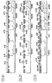
- Figs. 2A to 2L are cross-sectional views of a semiconductor device, illustrating respective steps, in order, of a conventional method of fabricating a semiconductor device including a logic circuit and a high-voltage circuit on a common semiconductor substrate.
- a low-voltage NMOS transistor, a low-voltage PMOS transistor, a high-voltage NMOS transistor, and a high-voltage PMOS transistor are all to be fabricated on a common p-type silicon substrate.
- a p-type silicon substrate 401 having an impurity concentration in the range of 0.5 ⁇ 10 16 to 1 ⁇ 10 16 cm -3 .
- an oxide film 402 is grown by a thickness of 480 nm on the p-type silicon substrate 401, followed by deposition a photoresist film 403 all over the oxide film 402. Then, a first photolithography and etching step is carried out to thereby partially remove the oxide film 402 in regions where high-voltage and low-voltage n-type well regions are to be formed, with the photoresist film 403 being used as an etching mask.
- a thin oxide film 491 is grown on a surface of the p-type silicon substrate 401 in exposed regions thereof.
- the oxide film 491 has a thickness of about 40 nm.
- the oxide film 491 is grown for preventing channeling in ion-implantation and precipitation of impurities caused by thermal annealing carried out at a high temperature.
- the p-type silicon substrate 1 is implanted at 150 KeV with doses of 1 ⁇ 10 13 cm -2 of n-type impurity ions such as phosphorus with the oxide film 402 being used as an ion-implantation mask.
- a first annealing is carried out at 1200°C for about 5 hours.
- the ion-implanted regions or n-type impurity regions 404A, 404B and 404D are diffused laterally and in a depth-wise direction of the p-type silicon substrate 401 to thereby make impurity regions 405A, 405B and 405D, as illustrated in Fig. 2C.
- the oxide film 491 is all removed, and then a thin oxide film 492 is formed again at a surface of the p-type silicon substrate 401.
- a photoresist film 403 is formed again entirely over the oxide film 492.
- a second lithography step is carried out to the photoresist film 403 employing an alignment mark having been formed in the first lithography step, to thereby pattern the photoresist film 403 into a desired pattern.
- p-type impurities are ion-implanted into the n-type well region 405B in a selected area with the patterned photoresist film 403 being used as a mask, to thereby form an impurity region 406B in the n-type well region 405B, as illustrated in Fig. 2D.
- the thus formed impurity region 406 will make a high-voltage p-type well for the high-voltage PMOS transistor.
- a nitride film 407 is grown on the oxide film 492 by a thickness in the range of 150 nm to 240 nm, for instance.
- a photoresist film 403 is deposited all over the nitride film 407, followed by a third photolithography step to thereby pattern the photoresist film 403.
- the nitride film 407 is etched for removal in selected regions where device isolation regions are to be formed, with the patterned photoresist film 403 being used as a mask.
- the product is oxidized at 1000°C to 1200°C for about 3 hours. This oxidation doubles as a second annealing.
- device isolation oxide films 410 are formed at a surface of the p-type silicon substrate 410.
- the oxide films 410 have a thickness in the range of about 50 nm to about 70 nm.
- LOCOS for defining device formation regions.
- LOPOS or trench type LOCOS may be substituted for LOCOS, in which case, a distance Xn2 (see Fig. 2F) between the oxide film 410 and an outer boundary of the n-type impurity region 408A varies in dependence on a target breakdown voltage of the high-voltage NMOS transistor, and further a distance Xp2 (see Fig. 2F) between the oxide film 410 and an outer boundary of the p-type impurity region 409B varies in dependence on a target breakdown voltage of the high-voltage PMOS transistor.
- the distances Xn2 and Xp2 are dependent on the first and second annealing, and hence the first and second annealing are carried out in a certain range of a temperature and a period of time.
- an oxide film 411 which will make a dielectric, insulating film of MOS transistors is grown at a surface of the p-type silicon substrate 401.
- a photoresist film 403 is deposited entirely over the product, and patterned into a desired pattern in a fourth photolithography step. Then, the dielectric, insulating film 411 is removed in a selected region where the low-voltage MOS transistors are to be formed, with the patterned photoresist film 403 being used as a mask, as illustrated in Fig. 2H.
- an oxide film or a dielectric, insulating film 412 for the low-voltage MOS transistors is grown at a surface of the silicon substrate, as illustrated in Fig. 2I.
- the oxide film or dielectric, insulating film 411 for the high-voltage MOS transistors is concurrently grown into an insulating film 413.
- a film 414 which will make gate electrodes of MOS transistors is grown all over the product.
- the film 414 is made of polysilicon or a multi-layered structure of polysilicon and metal silicide.
- a photoresist film (not illustrated) is deposited all over the polysilicon film 414, and then is patterned into a desired pattern by a fifth photolithography. Then, as illustrated in Fig. 2K, the polysilicon film 414 is etched in selected regions with the patterned photoresist film being used as an etching mask. As a result, there are formed gate electrodes 414C, 414D, 414A and 414B of the low-voltage NMOS transistor, the low-voltage PMOS transistor, the high-voltage NMOS transistor and the high-voltage PMOS transistor respectively.
- Those layers 421, 424, 422, 425, 423 and 426 are formed of highly doped n-type impurity regions.
- Those layers 432, 435, 433, 436, 431 and 434 are formed of highly doped p-type impurity regions. Thereafter, the thus formed drain, source, gate and channel well electrodes are electrically connected with each other through metal wiring layers in a conventional manner to thereby complete LSI.
- parameters for determining a breakdown voltage are concentrations of impurities in both an extended drain region and a channel region, and a distance between an outer end of an extended drain region and a device isolation layer, that is, distances Xn1 and Xp1 as illustrated in Figs. 1A and 1B.
- Figs. 3A and 3B show the relation between the above-mentioned parameters and a breakdown voltage.
- the impurity concentration is dependent on both an amount of impurities and a time of annealing at a high temperature (generally, a few hours to about 10 hours at 1000°C to 1200°C). In the conventional method, since high temperature thermal annealing is carried out a lot of times, it is quite difficult to control the impurity concentration with high accuracy.
- the above-mentioned distances Xn1 and Xp1 correspond to distances Xn3 and Xp3 illustrated in Fig. 2L.
- the distance Xn3 in the high-voltage NMOS transistor is determined in a complicated manner. That is, the distance Xn3 is dependent on the lateral diffusion of the region 404A, into which n-type impurities have been implanted in Fig. 2B, caused by two high temperature thermal annealing.
- the distance Xp3 in the high-voltage PMOS transistor is determined in a more complicated manner.
- the region 406B having been formed by implanting p-type impurities thereinto with the oxide film 402 being used as an alignment mark is laterally diffused by the first high temperature annealing to thereby make the high-voltage p-type well region 409B illustrated in Fig. 2L.
- the device isolation oxide film 410 is formed also with the oxide film 402 being used as an alignment mark. Namely, the distance Xp2 between the device isolation oxide film 410 and an outer end of the high-voltage p-type well region 409B is formed under the influence of both a dispersion caused by two photolithography steps and a dispersion caused by a high temperature thermal annealing step. Hence, there is generated a dispersion in a breakdown voltage of both the high-voltage NMOS and PMOS transistors.
- MOS transistors When an electronic circuit is to be formed of MOS transistors, designability of a circuit may be enhanced, if a channel region of MOS transistors is electrically independent from a semiconductor substrate. For instance, in a circuit which employs NMOS transistor, and is called a negative power-supply circuit because it deals with a voltage lower than a voltage of a semiconductor substrate, a channel region of MOS transistor has to be electrically isolated from a semiconductor substrate.
- the channel region of the high-voltage PMOS transistor is electrically isolated from the silicon substrate, but the channel region of the high-voltage NMOS transistor is kept at the same voltage as that of the silicon substrate, which restricts the designability of a semiconductor device.
- Japanese Patent Publication No. 2510751 Japanese Unexamined Patent Publication No. 2-284462 published on November 21, 1990
- U. S. patent application No. 324,869 filed on March 17, 1989 by Delco Electronics Corporation has suggested a method of fabricating high-voltage and low-voltage CMOS transistors on a common integrated circuit chip.
- an extended drain well region having a first conductivity, of a high-voltage transistor having a first conductivity is formed concurrently with well regions having a first conductivity, of high-voltage and low-voltage transistors having a second conductivity, and an extended drain well region having a second conductivity, of a high-voltage transistor having a second conductivity is formed by ion-implantation separate from the above-mentioned well region having a first conductivity.
- Japanese Unexamined Patent Publication No. 7-307394 based on U. S. patent application No. 224,948 filed on April 8, 1994 by Texas Instrument Incorporated has suggested an extended drain resurf lateral DMOS device.
- a method of readily fabricating an integrated circuit including a high-voltage PMOS device and/or high-voltage NMOS device, and a low-voltage PMOS device and/or low-voltage NMOS device.
- Another object of the present invention is to provide a semiconductor device in which both an electrically conductive region serving as a channel region of high-voltage NMOS transistor and an electrically conductive region serving as a channel region of high-voltage PMOS transistor are electrically independent from a semiconductor substrate. It is also another object of the present invention to provide a method of fabricating the above-mentioned semiconductor device.
- a further object of the present invention is to provide a semiconductor device in which a distance between an extended drain region and a device isolation region can be controlled with high accuracy, and also provide a method of fabricating the same.
- a semiconductor device including (a) a semiconductor substrate having a first conductivity, (b) a first, low-voltage MOS transistor formed on the semiconductor substrate, (c) a second, high-voltage MOS transistor formed on the semiconductor substrate and having a first conductivity, (d) a third, high-voltage MOS transistor formed on the semiconductor substrate and having a second conductivity, characterized by that both a first electrically conductive region containing a channel region of the third MOS transistor and a second electrically conductive region containing an extended drain region of the second MOS transistor are electrically independent of the semiconductor substrate.
- the channel region and the extended drain region have a common conductivity, and that the channel region and the extended drain region have the same conductivity as that of the semiconductor substrate. It is preferable that the channel region and the extended drain region are both surrounded by well regions having a second conductivity. It is preferable that an insulating film formed below gate electrodes of the second and third MOS transistors at least partially has the same thickness as that of an insulating film formed below a gate electrode of the first MOS transistor.
- a method of fabricating a semiconductor device including the steps of (a) forming first well regions in a semiconductor substrate in all regions in which high-voltage and low-voltage MOS transistors are to be formed, the semiconductor substrate having a first conductivity and the first well regions having a second conductivity, (b) forming an isolation layer on the semiconductor substrate for isolating the first well regions from each other, (c) forming high-voltage well regions having a first conductivity and low-voltage well regions one of which has a first conductivity and another of which has a second conductivity, and (d) forming MOS transistors on the high-voltage and low-voltage well regions.
- the step (b) may be carried out prior to the step (a). It is preferable that the high-voltage and low-voltage well regions are formed with the isolation layer being used as a mark. For instance, the high-voltage well regions and the low-voltage well region having a first conductivity are first formed, and then the low-voltage well region having a second conductivity is formed in the step (c).
- the step (d) of forming MOS transistors on the well regions may include the steps of forming insulating films and gate electrodes for each of the MOS transistors, forming highly impurity-doped regions having a second conductivity, the highly impurity-doped regions serving as source and drain electrodes of NMOS transistors, and forming highly impurity-doped regions having a first conductivity, the highly impurity-doped regions serving as source and drain electrodes of PMOS transistors.
- the high-voltage and low-voltage well regions may be formed by ion-implantation into the semiconductor substrate through an insulating layer formed on a surface of the semiconductor substrate. It is preferable that annealing at 1000°C or greater is all carried out before the high-voltage well regions are formed. Namely, it is preferable that annealing at 1000°C or greater is not carried out after the high-voltage wells having a first conductivity have been formed.
- the high-voltage well regions are concurrently formed, and wherein one of the high-voltage well regions serves as an extended drain region of the high-voltage MOS transistor having a first conductivity, and the other of the high-voltage well regions serves as a channel region of the high-voltage MOS transistor having a second conductivity.
- NMOS and PMOS transistors are formed within high-voltage well regions having a conductivity opposite to a conductivity of a semiconductor substrate, all MOS transistors are electrically independent from the semiconductor substrate, ensuring designability of this kind of semiconductor device.
- a channel region and an extended drain region of high-voltage MOS transistors with a device isolation layer being used as a reference mark.
- a high temperature thermal annealing is not carried out after ion-implantation of impurities into a semiconductor substrate for forming the channel region and the extended drain region, it would be possible to control, with high accuracy, a distance between the channel region or extended drain region and the device isolation region both of which are factors for determining a breakdown voltage of high-voltage MOS transistors.
- Fig. 1A is a cross-sectional view of high-voltage NMOS transistor.
- Fig. 1B is a cross-sectional view of high-voltage PMOS transistor.
- Fig. 1C is a cross-sectional view of low-voltage NMOS transistor.
- Fig. 1D is a cross-sectional view of low-voltage PMOS transistor.
- Figs. 2A to 2L are cross-sectional views of a semiconductor device, illustrating respective steps, in order, of a conventional method of fabricating the same.
- Fig. 3A illustrates a relation between an impurity concentration of a high-voltage well region and a breakdown voltage of high-voltage MOS transistors.
- Fig. 3B illustrates a relation between (a) a distance between an extended drain region and a device isolation layer, and (b) a breakdown voltage of high-voltage MOS transistors.
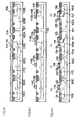
- Figs. 4A to 4K are cross-sectional views of a semiconductor device, illustrating respective steps, in order, of a method of fabricating the same in accordance with the first embodiment of the present invention.
- Figs. 5A to 5D are cross-sectional views of a semiconductor device, illustrating respective steps, in order, of a method of fabricating the same in accordance with the second embodiment of the present invention.
- an oxide film 102 is grown at a surface of the p-type silicon substrate 101 by a thickness of 480 nm.
- a photoresist film 103 is deposited all over the oxide film 102.
- the photoresist film 103 is patterned into a desired pattern in a first photolithography step.
- the oxide film 102 is etched with the thus patterned photoresist film 103 being used as an etching mask, to thereby remove the oxide film 102 in selected regions where high-voltage n-type well regions are to be formed.
- openings in the oxide film 102 so that n-type impurities may be ion-implanted into all or necessary regions in a low-voltage NMOS transistor 52, a low-voltage PMOS transistor 51, a high-voltage NMOS transistor 52, and a high-voltage PMOS transistor 53.
- openings are formed in the oxide film 102 in all regions where the transistors 51 to 54 are to be formed. However, for instance, an opening may not be formed in a region where the low-voltage PMOS transistor 51 is to be formed.
- a thin oxide film 191 is grown at the exposed regions of the silicon substrate 101 for preventing channeling of ion-implantation and precipitation of impurities caused by high temperature thermal annealing.
- the oxide film has a thickness of about 40 nm.
- the p-type silicon substrate 101 is implanted at 150 KeV with doses of 1 ⁇ 10 13 cm -2 of n-type impurity ions such as phosphorus with the oxide film 102 being used as an ion-implantation mask.
- impurity regions 104C, 104D, 104A and 104B at a surface of the silicon substrate 101.
- a first annealing is carried out at 1200°C for about 8 hours.
- the n-type impurity regions 104C, 104D, 104A and 104B are diffused laterally and in a depth-wise direction of the p-type silicon substrate 101 to thereby make diffusion regions 105C, 105D, 105A and 105B, as illustrated in Fig. 4C.
- the oxide films 102 and 191 are all removed, and then a thin oxide film 192 is formed again at a surface of the p-type silicon substrate 101.
- a nitride film 193 on the oxide film 192 by a thickness in the range of 150 to 240 nm, for instance.
- a photoresist film 103 is deposited all over the nitride film 193, followed by a second photolithography step to thereby pattern the photoresist film 103 into a desired pattern.
- the oxide film 192 and the nitride film 193 are etched for removal in selected regions where device isolation regions are to be formed, with the patterned photoresist film 103 being used as an etching mask.
- the silicon substrate 101 is further etched in the regions at a depth in the range of 50 to 80 nm, as illustrated in Fig. 4D.
- the product is oxidized at 950°C to 1050°C for about 2 hours.
- the oxidation is arranged so that an oxide film or device isolation film 109 to be formed at a surface of the silicon substrate 101 has a thickness in the range of about 50 to about 60 nm. This oxidation step is also carried out when only a low-voltage MOS transistor is fabricated, and hence is not an extra step.
- the high-voltage n-type well regions 105C, 105D, 105A and 105B are slightly diffused in the oxidation step, the lateral diffusion length of the high-voltage n-type well regions 105C, 105D, 105A and 105B does not exert an influence on a breakdown voltage of the high-voltage NMOS transistor, as mentioned later. Thereafter, the nitride film 193 is all removed. Thus, the device isolation step is completed.
- trench-type LOCOS for defining device formation regions.
- LOPOS or LOCOS may be substituted for trench-type LOCOS.
- trench device isolation may be employed.
- a photoresist film 103 is deposited all over the product, and is patterned into a desired pattern by a third photolithography step with the device isolation film 109, which has been formed in the second lithography step, being used as an alignment mark. Then, p-type impurities are ion-implanted into the selected regions through the oxide film 192. Thus, there are formed impurity regions 110C, 110A and 110B in the high-voltage n-type well regions 105C, 105A and 105B, respectively.
- the impurity region 110A will make a channel well of the high-voltage NMOS transistor 54, the impurity region 110B will make an extended drain electrode of the high-voltage PMOS transistor 53, and the impurity region 110C will make a channel well of the low-voltage NMOS transistor 52. Since the locations of the impurity regions 110A and 110B are determined in the lithography step carried out with the device isolation film 109 being used as a reference mark, and are not diffused in the subsequent thermal annealing, the distances Xn1 and Xp1, which are important factors for a high-voltage MOS transistor, would have a small dispersion.
- a photoresist film 103 is deposited all over the product, and is patterned into a desired pattern in a fourth photolithography step, as illustrated in Fig. 4G.
- n-type impurities are ion-implanted in a selected region in the high-voltage n-type well region 105D through the oxide film 192 with the patterned photoresist film 103 being used as a mask, to thereby form an impurity region 111D in the high-voltage n-type well region 105D.
- the thus formed impurity region 111D will make a channel well of the low-voltage PMOS transistor 51.
- This step of forming the impurity region 111D by ion-implantation is also carried out when only a low-voltage MOS transistor is to be formed, and hence is not an extra step.
- an oxide film 113 serving as a dielectric, insulating film of the MOS transistors is formed at a surface of the silicon substrate 101, as illustrated in Fig. 4H.
- a film 114 which will make gate electrodes of the MOS transistors is grown all over the product.
- the film 114 is made of a multi-layered structure of polysilicon and metal silicide.
- the film 114 may be made of only polysilicon.
- a photoresist film (not illustrated) is deposited all over the multi-layered film 114, and then is patterned into a desired pattern by a fifth photolithography. Then, as illustrated in Fig. 4J, the multi-layered film 114 is etched in selected regions with the patterned photoresist film being used as an etching mask. As a result, there are formed gate electrodes 114C, 114D, 114A and 114B of the low-voltage NMOS transistor 52, the low-voltage PMOS transistor 51, the high-voltage NMOS transistor 54, and the high-voltage PMOS transistor 53, respectively.
- source electrodes 121, 124 and drain electrodes 122, 125 of the low-voltage NMOS transistor 52 and the high-voltage NMOS transistor 54 there are formed source electrodes 121, 124 and drain electrodes 122, 125 of the low-voltage NMOS transistor 52 and the high-voltage NMOS transistor 54, and channel well electrodes 123 and 126 of the low-voltage PMOS transistor 51 and the high-voltage PMOS transistor 53.
- Those electrodes 121, 124, 122, 125, 123 and 126 are formed of highly doped n-type impurity regions.
- Those layers 132, 135, 133, 136, 131 and 134 are formed of highly doped p-type impurity regions.
- the thus formed drain, source, gate and channel well electrodes are electrically connected with each other through metal wiring layers (not illustrated) in a conventional manner to thereby complete LSI.
- NMOS and PMOS transistors in accordance with the above-mentioned first embodiment, it is possible to form low-voltage and high-voltage NMOS and PMOS transistors in a common semiconductor substrate by adding the smallest number of fabrication steps to a conventional method.
- high-voltage and low-voltage NMOS and PMOS transistors are formed within high-voltage well regions having a conductivity opposite to a conductivity of a semiconductor substrate, all MOS transistors are electrically independent from the semiconductor substrate, ensuring designability of a circuit.
- a step of high temperature annealing at 1000°C or greater after the step illustrated in Fig. 4E has been completed, there does not exist a step of high temperature annealing at 1000°C or greater.
- the impurity region 110A which will make a channel well of the high-voltage NMOS transistor 54
- the impurity region 110B which will make an extended drain electrode of the high-voltage PMOS transistor 53
- the impurity region 110C which will make a channel well of the low-voltage NMOS transistor 52.
- Those impurity regions 110A, 110B and 110C are formed by ion-implantation with the device isolation film 109 being used as an alignment mark.
- the distances Xn1 and Xp1 which are important factors for determining a breakdown voltage of the high-voltage MOS transistor, within a dispersion caused by a single photolithography step. Namely, the distances Xn1 and Xp1 can be controlled with high accuracy.
- a desired breakdown voltage in the range of 20V to 80V merely by adjusting an amount of n-type impurities to be implanted into the silicon substrate in the step of forming the high-voltage n-type well regions.
- the second embodiment is characterized by that a device isolation step is carried out at first.
- a thin oxide film 291 is formed on a surface of a semiconductor substrate 201, and then a nitride film 207 is grown all over the oxide film 291 by a thickness in the range of 150 nm to 240 nm, for instance.
- a photoresist film 203 is deposited all over the nitride film 207, followed by a first photolithography step to thereby pattern the photoresist film 203 into a desired pattern.
- the oxide film 291 and the nitride film 207 are etched for removal in selected regions where device isolation regions are to be formed, with the patterned photoresist film 203 being used as an etching mask.
- the silicon substrate 201 is further etched in the regions at a depth in the range of 50 nm to 80 nm, as illustrated in Fig. 5A.
- the product is oxidized at 950°C to 1050°C for about 2 hours.
- the oxidation is arranged so that an oxide film or device isolation film 209 to be formed at a surface of the silicon substrate 201 has a thickness in the range of about 50 nm to about 60 nm.
- This oxidation step is also carried out when only a low-voltage MOS transistor is fabricated, and hence is not an extra step.
- the nitride film 207 is all removed.
- the device isolation step is completed.
- trench-type LOCOS for forming device isolation films
- trench device isolation including the steps of etching a semiconductor substrate in device isolation regions by a depth in the range of 30 nm to 40 nm, filling the etched regions with an oxide film by low-temperature oxide film growth, and polishing the oxide film to thereby form the device isolation film 209.
- the device isolation film 209 After the formation of the device isolation film 209, there is grown a thin oxide film 291 at a surface of the semiconductor substrate 201, as illustrated in Fig. 5B.
- a photoresist film 203 is deposited all over the product, and is patterned into a desired pattern by a second photolithography step. Then, n-type impurities are ion-implanted into the selected regions through the oxide film 291. Thus, there are formed impurity regions 205C, 205D, 205A and 205B in the semiconductor substrate 201, as illustrated in Fig. 5C.
- a photoresist film 203 is deposited all over the product, and is patterned into a desired pattern by a third photolithography step with the device isolation film 209, which has been formed in the second lithography step, being used as an alignment mark. Then, p-type impurities are ion-implanted into the selected regions through the oxide film 291. Thus, there are formed impurity regions 210C, 210A and 210B in the high-voltage n-type well regions 205C, 205A and 205B, respectively.
- the above-mentioned second embodiment provides the same advantages as those obtained by the first embodiment.
- the fabrication steps are simplified, and the distances Xn1 and Xp1 are made with higher accuracy.
Landscapes
- Metal-Oxide And Bipolar Metal-Oxide Semiconductor Integrated Circuits (AREA)
- Insulated Gate Type Field-Effect Transistor (AREA)
Applications Claiming Priority (2)
| Application Number | Priority Date | Filing Date | Title |
|---|---|---|---|
| JP340694/96 | 1996-12-20 | ||
| JP8340694A JPH10189762A (ja) | 1996-12-20 | 1996-12-20 | 半導体装置およびその製造方法 |
Publications (2)
| Publication Number | Publication Date |
|---|---|
| EP0849801A2 true EP0849801A2 (fr) | 1998-06-24 |
| EP0849801A3 EP0849801A3 (fr) | 1998-09-23 |
Family
ID=18339424
Family Applications (1)
| Application Number | Title | Priority Date | Filing Date |
|---|---|---|---|
| EP97122323A Withdrawn EP0849801A3 (fr) | 1996-12-20 | 1997-12-17 | Dispositif semiconducteur comprenant des transistors MOS du type N et P sur un substrat commun et méthode de fabrication |
Country Status (4)
| Country | Link |
|---|---|
| US (1) | US6451640B1 (fr) |
| EP (1) | EP0849801A3 (fr) |
| JP (1) | JPH10189762A (fr) |
| CN (1) | CN1135623C (fr) |
Cited By (4)
| Publication number | Priority date | Publication date | Assignee | Title |
|---|---|---|---|---|
| US6451640B1 (en) * | 1996-12-20 | 2002-09-17 | Nec Corporation | Semiconductor device having NMOS and PMOS transistors on common substrate and method of fabricating the same |
| WO2003021685A1 (fr) | 2001-08-30 | 2003-03-13 | Sony Corporation | Dispositif semi-conducteur et son procede de production |
| US6693331B2 (en) * | 1999-11-18 | 2004-02-17 | Intel Corporation | Method of fabricating dual threshold voltage n-channel and p-channel MOSFETS with a single extra masked implant operation |
| DE10225860B4 (de) * | 2001-06-11 | 2006-11-09 | Fuji Electric Co., Ltd., Kawasaki | Halbleiterbauteil |
Families Citing this family (31)
| Publication number | Priority date | Publication date | Assignee | Title |
|---|---|---|---|---|
| JP4674293B2 (ja) * | 1998-08-21 | 2011-04-20 | 株式会社 日立ディスプレイズ | Mosトランジスタの製造方法 |
| DE69942418D1 (de) * | 1999-11-19 | 2010-07-08 | St Microelectronics Srl | Herstellungsverfahren für elektronische Bauelemente mit Hochspannungs-MOS- und EEPROM-Transistoren |
| SE519382C2 (sv) * | 2000-11-03 | 2003-02-25 | Ericsson Telefon Ab L M | Integrering av självinriktade MOS-högspänningskomponenter samt halvledarstruktur innefattande sådana |
| JP2003197908A (ja) * | 2001-09-12 | 2003-07-11 | Seiko Instruments Inc | 半導体素子及びその製造方法 |
| US6710424B2 (en) | 2001-09-21 | 2004-03-23 | Airip | RF chipset architecture |
| JP3719192B2 (ja) * | 2001-10-26 | 2005-11-24 | セイコーエプソン株式会社 | 半導体装置の製造方法 |
| JP3546037B2 (ja) * | 2001-12-03 | 2004-07-21 | 松下電器産業株式会社 | 半導体装置の製造方法 |
| JP2003258120A (ja) * | 2002-03-07 | 2003-09-12 | Seiko Epson Corp | 半導体装置の製造方法 |
| US7253276B2 (en) * | 2003-01-03 | 2007-08-07 | The Texas A&M University System | Stem-regulated, plant defense promoter and uses thereof in tissue-specific expression in monocots |
| WO2004090983A1 (fr) * | 2003-04-04 | 2004-10-21 | Fujitsu Limited | Dispositif a semi-conducteur et son procede de production |
| JP2004311891A (ja) * | 2003-04-10 | 2004-11-04 | Seiko Instruments Inc | 半導体装置 |
| KR100961549B1 (ko) | 2003-07-29 | 2010-06-07 | 매그나칩 반도체 유한회사 | 고전압 트랜지스터 및 로직 트랜지스터를 갖는 반도체 소자 |
| JP4707947B2 (ja) * | 2003-11-14 | 2011-06-22 | ルネサスエレクトロニクス株式会社 | 半導体装置 |
| US7091556B2 (en) * | 2003-12-24 | 2006-08-15 | Texas Instruments Incorporated | High voltage drain-extended transistor |
| WO2006018974A1 (fr) * | 2004-08-17 | 2006-02-23 | Rohm Co., Ltd. | Dispositif semi-conducteur et procédé de fabrication dudit dispositif |
| JP2006324346A (ja) * | 2005-05-17 | 2006-11-30 | Matsushita Electric Ind Co Ltd | 半導体装置およびその製造方法 |
| JP4956987B2 (ja) * | 2005-12-16 | 2012-06-20 | 株式会社島津製作所 | レーザー結晶化装置及び結晶化方法 |
| KR100690924B1 (ko) * | 2005-12-21 | 2007-03-09 | 삼성전자주식회사 | 반도체 집적 회로 장치와 그 제조 방법 |
| KR100760917B1 (ko) * | 2006-10-27 | 2007-09-21 | 동부일렉트로닉스 주식회사 | 고전압 반도체 소자의 제조방법 |
| KR100917216B1 (ko) * | 2007-02-02 | 2009-09-16 | 삼성전자주식회사 | 반도체 소자 및 그 형성방법 |
| DE102007034800A1 (de) * | 2007-03-26 | 2008-10-02 | X-Fab Dresden Gmbh & Co. Kg | Maskensparende Herstellung komplementärer lateraler Hochvolttransistoren mit RESURF-Struktur |
| KR100903483B1 (ko) | 2007-11-26 | 2009-06-18 | 주식회사 동부하이텍 | 반도체 소자의 제조방법 |
| JP4645861B2 (ja) * | 2008-07-03 | 2011-03-09 | セイコーエプソン株式会社 | 半導体装置の製造方法 |
| US8247280B2 (en) | 2009-10-20 | 2012-08-21 | Taiwan Semiconductor Manufacturing Company, Ltd. | Integration of low and high voltage CMOS devices |
| DE102010014370B4 (de) * | 2010-04-09 | 2021-12-02 | X-Fab Semiconductor Foundries Ag | LDMOS-Transistor und LDMOS - Bauteil |
| JP5605241B2 (ja) * | 2011-01-27 | 2014-10-15 | 富士通セミコンダクター株式会社 | Mosトランジスタおよび半導体集積回路装置の製造方法 |
| CN102446961B (zh) * | 2011-12-09 | 2014-05-28 | 无锡中星微电子有限公司 | 包含功率器件的半导体装置及其制备方法 |
| JP6115056B2 (ja) * | 2012-09-18 | 2017-04-19 | 株式会社Jvcケンウッド | 液晶表示装置 |
| TW201434136A (zh) * | 2013-02-27 | 2014-09-01 | 天鈺科技股份有限公司 | 半導體器件及顯示裝置 |
| US9548307B2 (en) * | 2014-06-30 | 2017-01-17 | Alpha And Omega Semiconductor Incorporated | Compact CMOS device isolation |
| CN108847423B (zh) * | 2018-05-30 | 2022-10-21 | 矽力杰半导体技术(杭州)有限公司 | 半导体器件及其制造方法 |
Family Cites Families (17)
| Publication number | Priority date | Publication date | Assignee | Title |
|---|---|---|---|---|
| DE2940954A1 (de) | 1979-10-09 | 1981-04-23 | Nixdorf Computer Ag, 4790 Paderborn | Verfahren zur herstellung von hochspannungs-mos-transistoren enthaltenden mos-integrierten schaltkreisen sowie schaltungsanordnung zum schalten von leistungsstromkreisen unter verwendung derartiger hochspannungs-mos-transistoren |
| FR2571178B1 (fr) * | 1984-09-28 | 1986-11-21 | Thomson Csf | Structure de circuit integre comportant des transistors cmos a tenue en tension elevee, et son procede de fabrication |
| JPS62155555A (ja) | 1985-09-18 | 1987-07-10 | Sony Corp | 相補型mosトランジスタ |
| US5043788A (en) * | 1988-08-26 | 1991-08-27 | Mitsubishi Denki Kabushiki Kaisha | Semiconductor device with functional portions having different operating voltages on one semiconductor substrate |
| US5047358A (en) * | 1989-03-17 | 1991-09-10 | Delco Electronics Corporation | Process for forming high and low voltage CMOS transistors on a single integrated circuit chip |
| US4918026A (en) * | 1989-03-17 | 1990-04-17 | Delco Electronics Corporation | Process for forming vertical bipolar transistors and high voltage CMOS in a single integrated circuit chip |
| JP2861624B2 (ja) * | 1992-05-13 | 1999-02-24 | 日本電気株式会社 | 半導体装置の製造方法 |
| JPH06295863A (ja) | 1993-04-08 | 1994-10-21 | Japan Energy Corp | 高抵抗化合物半導体の製造方法 |
| US5468666A (en) | 1993-04-29 | 1995-11-21 | Texas Instruments Incorporated | Using a change in doping of poly gate to permit placing both high voltage and low voltage transistors on the same chip |
| US5472887A (en) * | 1993-11-09 | 1995-12-05 | Texas Instruments Incorporated | Method of fabricating semiconductor device having high-and low-voltage MOS transistors |
| JP2920061B2 (ja) | 1994-02-04 | 1999-07-19 | モトローラ株式会社 | 高負荷駆動ドライバ用半導体集積装置及び高負荷駆動ドライバ装置 |
| KR100331127B1 (ko) * | 1994-02-15 | 2002-10-18 | 내셔널 세미콘덕터 코포레이션 | 표준cmos공정용고전압cmos트랜지스터 |
| US5475335A (en) * | 1994-04-01 | 1995-12-12 | National Semiconductor Corporation | High voltage cascaded charge pump |
| US5498554A (en) * | 1994-04-08 | 1996-03-12 | Texas Instruments Incorporated | Method of making extended drain resurf lateral DMOS devices |
| JPH08191107A (ja) * | 1995-01-11 | 1996-07-23 | Mitsubishi Electric Corp | 半導体装置とその製造方法 |
| JP3386101B2 (ja) * | 1996-08-29 | 2003-03-17 | シャープ株式会社 | 半導体装置の製造方法 |
| JPH10189762A (ja) * | 1996-12-20 | 1998-07-21 | Nec Corp | 半導体装置およびその製造方法 |
-
1996
- 1996-12-20 JP JP8340694A patent/JPH10189762A/ja active Pending
-
1997
- 1997-12-17 EP EP97122323A patent/EP0849801A3/fr not_active Withdrawn
- 1997-12-22 CN CNB971220980A patent/CN1135623C/zh not_active Expired - Fee Related
-
2000
- 2000-07-05 US US09/609,352 patent/US6451640B1/en not_active Expired - Fee Related
Cited By (7)
| Publication number | Priority date | Publication date | Assignee | Title |
|---|---|---|---|---|
| US6451640B1 (en) * | 1996-12-20 | 2002-09-17 | Nec Corporation | Semiconductor device having NMOS and PMOS transistors on common substrate and method of fabricating the same |
| US6693331B2 (en) * | 1999-11-18 | 2004-02-17 | Intel Corporation | Method of fabricating dual threshold voltage n-channel and p-channel MOSFETS with a single extra masked implant operation |
| DE10225860B4 (de) * | 2001-06-11 | 2006-11-09 | Fuji Electric Co., Ltd., Kawasaki | Halbleiterbauteil |
| WO2003021685A1 (fr) | 2001-08-30 | 2003-03-13 | Sony Corporation | Dispositif semi-conducteur et son procede de production |
| US6869847B2 (en) | 2001-08-30 | 2005-03-22 | Sony Corporation | Semiconductor device manufacturing method thereof |
| US7122861B2 (en) | 2001-08-30 | 2006-10-17 | Sony Corporation | Semiconductor device and manufacturing method thereof |
| EP1422759A4 (fr) * | 2001-08-30 | 2008-03-19 | Sony Corp | Dispositif semi-conducteur et son procede de production |
Also Published As
| Publication number | Publication date |
|---|---|
| JPH10189762A (ja) | 1998-07-21 |
| EP0849801A3 (fr) | 1998-09-23 |
| CN1135623C (zh) | 2004-01-21 |
| US6451640B1 (en) | 2002-09-17 |
| CN1189694A (zh) | 1998-08-05 |
Similar Documents
| Publication | Publication Date | Title |
|---|---|---|
| EP0849801A2 (fr) | Dispositif semiconducteur comprenant des transistors MOS du type N et P sur un substrat commun et méthode de fabrication | |
| US6548874B1 (en) | Higher voltage transistors for sub micron CMOS processes | |
| US6900101B2 (en) | LDMOS transistors and methods for making the same | |
| US5185535A (en) | Control of backgate bias for low power high speed CMOS/SOI devices | |
| US7301185B2 (en) | High-voltage transistor device having an interlayer dielectric etch stop layer for preventing leakage and improving breakdown voltage | |
| US6501139B1 (en) | High-voltage transistor and fabrication process | |
| US6855581B2 (en) | Method for fabricating a high-voltage high-power integrated circuit device | |
| US6163053A (en) | Semiconductor device having opposite-polarity region under channel | |
| EP0596468A2 (fr) | MOSFET de type LDD et sa méthode de fabrication | |
| JPH0613617A (ja) | パワーmosfetトランジスタの製造方法 | |
| US20080188048A1 (en) | Semiconductor device | |
| EP0962988B1 (fr) | Dispositif semi-conducteur de type SOI et sa méthode de fabrication | |
| US20030127694A1 (en) | Higher voltage transistors for sub micron CMOS processes | |
| US6608336B2 (en) | Lateral double diffused MOS transistor | |
| KR100424603B1 (ko) | 반도체 장치의 제조 방법 | |
| US6348382B1 (en) | Integration process to increase high voltage breakdown performance | |
| CN100438072C (zh) | 半导体器件及其制作方法 | |
| JP3380117B2 (ja) | 半導体装置とその製造方法 | |
| US6853038B2 (en) | Semiconductor device and method for manufacturing the same | |
| KR0139773B1 (ko) | 반도체 집적 회로 장치 및 그 제조 방법 | |
| US7224023B2 (en) | Semiconductor device and method of manufacturing thereof | |
| US6110788A (en) | Surface channel MOS transistors, methods for making the same, and semiconductor devices containing the same | |
| US6929994B2 (en) | Method for manufacturing semiconductor device that includes well formation | |
| JP2006032493A (ja) | 半導体装置及びその製造方法 | |
| US7687363B2 (en) | Method for manufacturing semiconductor device |
Legal Events
| Date | Code | Title | Description |
|---|---|---|---|
| PUAI | Public reference made under article 153(3) epc to a published international application that has entered the european phase |
Free format text: ORIGINAL CODE: 0009012 |
|
| AK | Designated contracting states |
Kind code of ref document: A2 Designated state(s): DE FR GB |
|
| AX | Request for extension of the european patent |
Free format text: AL;LT;LV;MK;RO;SI |
|
| PUAL | Search report despatched |
Free format text: ORIGINAL CODE: 0009013 |
|
| AK | Designated contracting states |
Kind code of ref document: A3 Designated state(s): AT BE CH DE DK ES FI FR GB GR IE IT LI LU MC NL PT SE |
|
| AX | Request for extension of the european patent |
Free format text: AL;LT;LV;MK;RO;SI |
|
| 17P | Request for examination filed |
Effective date: 19980925 |
|
| AKX | Designation fees paid |
Free format text: DE FR GB |
|
| RBV | Designated contracting states (corrected) |
Designated state(s): DE FR GB |
|
| RAP1 | Party data changed (applicant data changed or rights of an application transferred) |
Owner name: NEC ELECTRONICS CORPORATION |
|
| 17Q | First examination report despatched |
Effective date: 20050118 |
|
| STAA | Information on the status of an ep patent application or granted ep patent |
Free format text: STATUS: THE APPLICATION IS DEEMED TO BE WITHDRAWN |
|
| 18D | Application deemed to be withdrawn |
Effective date: 20060215 |