EP0850826A2 - Pedalier pour bicyclette et procédé de fabrication - Google Patents
Pedalier pour bicyclette et procédé de fabrication Download PDFInfo
- Publication number
- EP0850826A2 EP0850826A2 EP97310475A EP97310475A EP0850826A2 EP 0850826 A2 EP0850826 A2 EP 0850826A2 EP 97310475 A EP97310475 A EP 97310475A EP 97310475 A EP97310475 A EP 97310475A EP 0850826 A2 EP0850826 A2 EP 0850826A2
- Authority
- EP
- European Patent Office
- Prior art keywords
- crank arm
- crank
- attachment hole
- core
- shell
- Prior art date
- Legal status (The legal status is an assumption and is not a legal conclusion. Google has not performed a legal analysis and makes no representation as to the accuracy of the status listed.)
- Granted
Links
- 238000000034 method Methods 0.000 title claims abstract description 17
- 238000004519 manufacturing process Methods 0.000 title claims abstract description 8
- 229910052751 metal Inorganic materials 0.000 claims abstract description 40
- 239000002184 metal Substances 0.000 claims abstract description 40
- 239000000945 filler Substances 0.000 claims abstract description 29
- 239000000463 material Substances 0.000 claims abstract description 26
- 238000005266 casting Methods 0.000 claims abstract description 23
- 239000000155 melt Substances 0.000 claims abstract description 13
- 238000005553 drilling Methods 0.000 claims abstract description 6
- 238000005242 forging Methods 0.000 claims description 16
- 230000005484 gravity Effects 0.000 claims description 11
- 230000007423 decrease Effects 0.000 claims description 4
- 239000005335 volcanic glass Substances 0.000 claims description 4
- 230000002093 peripheral effect Effects 0.000 claims 1
- 239000011148 porous material Substances 0.000 claims 1
- VYPSYNLAJGMNEJ-UHFFFAOYSA-N Silicium dioxide Chemical compound O=[Si]=O VYPSYNLAJGMNEJ-UHFFFAOYSA-N 0.000 description 3
- 238000003754 machining Methods 0.000 description 3
- 229910000838 Al alloy Inorganic materials 0.000 description 2
- PPBRXRYQALVLMV-UHFFFAOYSA-N Styrene Chemical compound C=CC1=CC=CC=C1 PPBRXRYQALVLMV-UHFFFAOYSA-N 0.000 description 2
- GWEVSGVZZGPLCZ-UHFFFAOYSA-N Titan oxide Chemical compound O=[Ti]=O GWEVSGVZZGPLCZ-UHFFFAOYSA-N 0.000 description 2
- 230000006835 compression Effects 0.000 description 2
- 238000007906 compression Methods 0.000 description 2
- 238000000465 moulding Methods 0.000 description 2
- 239000002245 particle Substances 0.000 description 2
- -1 (77.3) Inorganic materials 0.000 description 1
- KKCBUQHMOMHUOY-UHFFFAOYSA-N Na2O Inorganic materials [O-2].[Na+].[Na+] KKCBUQHMOMHUOY-UHFFFAOYSA-N 0.000 description 1
- 229910052782 aluminium Inorganic materials 0.000 description 1
- XAGFODPZIPBFFR-UHFFFAOYSA-N aluminium Chemical compound [Al] XAGFODPZIPBFFR-UHFFFAOYSA-N 0.000 description 1
- PNEYBMLMFCGWSK-UHFFFAOYSA-N aluminium oxide Inorganic materials [O-2].[O-2].[O-2].[Al+3].[Al+3] PNEYBMLMFCGWSK-UHFFFAOYSA-N 0.000 description 1
- 229910052681 coesite Inorganic materials 0.000 description 1
- 229910052593 corundum Inorganic materials 0.000 description 1
- 229910052906 cristobalite Inorganic materials 0.000 description 1
- 238000005520 cutting process Methods 0.000 description 1
- 238000001125 extrusion Methods 0.000 description 1
- 238000000227 grinding Methods 0.000 description 1
- 239000010440 gypsum Substances 0.000 description 1
- 229910052602 gypsum Inorganic materials 0.000 description 1
- 229910001234 light alloy Inorganic materials 0.000 description 1
- 239000011159 matrix material Substances 0.000 description 1
- 238000012986 modification Methods 0.000 description 1
- 230000004048 modification Effects 0.000 description 1
- 238000005498 polishing Methods 0.000 description 1
- 239000008262 pumice Substances 0.000 description 1
- 239000004576 sand Substances 0.000 description 1
- 239000000377 silicon dioxide Substances 0.000 description 1
- 239000011343 solid material Substances 0.000 description 1
- 125000006850 spacer group Chemical group 0.000 description 1
- 229910052682 stishovite Inorganic materials 0.000 description 1
- 229910052905 tridymite Inorganic materials 0.000 description 1
- 238000003466 welding Methods 0.000 description 1
- 229910001845 yogo sapphire Inorganic materials 0.000 description 1
Images



Classifications
-
- B—PERFORMING OPERATIONS; TRANSPORTING
- B21—MECHANICAL METAL-WORKING WITHOUT ESSENTIALLY REMOVING MATERIAL; PUNCHING METAL
- B21J—FORGING; HAMMERING; PRESSING METAL; RIVETING; FORGE FURNACES
- B21J5/00—Methods for forging, hammering, or pressing; Special equipment or accessories therefor
-
- B—PERFORMING OPERATIONS; TRANSPORTING
- B21—MECHANICAL METAL-WORKING WITHOUT ESSENTIALLY REMOVING MATERIAL; PUNCHING METAL
- B21J—FORGING; HAMMERING; PRESSING METAL; RIVETING; FORGE FURNACES
- B21J5/00—Methods for forging, hammering, or pressing; Special equipment or accessories therefor
- B21J5/002—Hybrid process, e.g. forging following casting
-
- B—PERFORMING OPERATIONS; TRANSPORTING
- B21—MECHANICAL METAL-WORKING WITHOUT ESSENTIALLY REMOVING MATERIAL; PUNCHING METAL
- B21K—MAKING FORGED OR PRESSED METAL PRODUCTS, e.g. HORSE-SHOES, RIVETS, BOLTS OR WHEELS
- B21K17/00—Making sport articles, e.g. skates
-
- B—PERFORMING OPERATIONS; TRANSPORTING
- B21—MECHANICAL METAL-WORKING WITHOUT ESSENTIALLY REMOVING MATERIAL; PUNCHING METAL
- B21K—MAKING FORGED OR PRESSED METAL PRODUCTS, e.g. HORSE-SHOES, RIVETS, BOLTS OR WHEELS
- B21K21/00—Making hollow articles not covered by a single preceding sub-group
-
- B—PERFORMING OPERATIONS; TRANSPORTING
- B22—CASTING; POWDER METALLURGY
- B22D—CASTING OF METALS; CASTING OF OTHER SUBSTANCES BY THE SAME PROCESSES OR DEVICES
- B22D19/00—Casting in, on, or around objects which form part of the product
-
- B—PERFORMING OPERATIONS; TRANSPORTING
- B22—CASTING; POWDER METALLURGY
- B22D—CASTING OF METALS; CASTING OF OTHER SUBSTANCES BY THE SAME PROCESSES OR DEVICES
- B22D31/00—Cutting-off surplus material, e.g. gates; Cleaning and working on castings
- B22D31/002—Cleaning, working on castings
-
- B—PERFORMING OPERATIONS; TRANSPORTING
- B62—LAND VEHICLES FOR TRAVELLING OTHERWISE THAN ON RAILS
- B62M—RIDER PROPULSION OF WHEELED VEHICLES OR SLEDGES; POWERED PROPULSION OF SLEDGES OR SINGLE-TRACK CYCLES; TRANSMISSIONS SPECIALLY ADAPTED FOR SUCH VEHICLES
- B62M3/00—Construction of cranks operated by hand or foot
-
- Y—GENERAL TAGGING OF NEW TECHNOLOGICAL DEVELOPMENTS; GENERAL TAGGING OF CROSS-SECTIONAL TECHNOLOGIES SPANNING OVER SEVERAL SECTIONS OF THE IPC; TECHNICAL SUBJECTS COVERED BY FORMER USPC CROSS-REFERENCE ART COLLECTIONS [XRACs] AND DIGESTS
- Y10—TECHNICAL SUBJECTS COVERED BY FORMER USPC
- Y10T—TECHNICAL SUBJECTS COVERED BY FORMER US CLASSIFICATION
- Y10T29/00—Metal working
- Y10T29/49—Method of mechanical manufacture
- Y10T29/49616—Structural member making
- Y10T29/49622—Vehicular structural member making
-
- Y—GENERAL TAGGING OF NEW TECHNOLOGICAL DEVELOPMENTS; GENERAL TAGGING OF CROSS-SECTIONAL TECHNOLOGIES SPANNING OVER SEVERAL SECTIONS OF THE IPC; TECHNICAL SUBJECTS COVERED BY FORMER USPC CROSS-REFERENCE ART COLLECTIONS [XRACs] AND DIGESTS
- Y10—TECHNICAL SUBJECTS COVERED BY FORMER USPC
- Y10T—TECHNICAL SUBJECTS COVERED BY FORMER US CLASSIFICATION
- Y10T29/00—Metal working
- Y10T29/49—Method of mechanical manufacture
- Y10T29/4998—Combined manufacture including applying or shaping of fluent material
- Y10T29/49982—Coating
- Y10T29/49984—Coating and casting
-
- Y—GENERAL TAGGING OF NEW TECHNOLOGICAL DEVELOPMENTS; GENERAL TAGGING OF CROSS-SECTIONAL TECHNOLOGIES SPANNING OVER SEVERAL SECTIONS OF THE IPC; TECHNICAL SUBJECTS COVERED BY FORMER USPC CROSS-REFERENCE ART COLLECTIONS [XRACs] AND DIGESTS
- Y10—TECHNICAL SUBJECTS COVERED BY FORMER USPC
- Y10T—TECHNICAL SUBJECTS COVERED BY FORMER US CLASSIFICATION
- Y10T29/00—Metal working
- Y10T29/49—Method of mechanical manufacture
- Y10T29/4998—Combined manufacture including applying or shaping of fluent material
- Y10T29/49988—Metal casting
-
- Y—GENERAL TAGGING OF NEW TECHNOLOGICAL DEVELOPMENTS; GENERAL TAGGING OF CROSS-SECTIONAL TECHNOLOGIES SPANNING OVER SEVERAL SECTIONS OF THE IPC; TECHNICAL SUBJECTS COVERED BY FORMER USPC CROSS-REFERENCE ART COLLECTIONS [XRACs] AND DIGESTS
- Y10—TECHNICAL SUBJECTS COVERED BY FORMER USPC
- Y10T—TECHNICAL SUBJECTS COVERED BY FORMER US CLASSIFICATION
- Y10T29/00—Metal working
- Y10T29/49—Method of mechanical manufacture
- Y10T29/4998—Combined manufacture including applying or shaping of fluent material
- Y10T29/49988—Metal casting
- Y10T29/49989—Followed by cutting or removing material
-
- Y—GENERAL TAGGING OF NEW TECHNOLOGICAL DEVELOPMENTS; GENERAL TAGGING OF CROSS-SECTIONAL TECHNOLOGIES SPANNING OVER SEVERAL SECTIONS OF THE IPC; TECHNICAL SUBJECTS COVERED BY FORMER USPC CROSS-REFERENCE ART COLLECTIONS [XRACs] AND DIGESTS
- Y10—TECHNICAL SUBJECTS COVERED BY FORMER USPC
- Y10T—TECHNICAL SUBJECTS COVERED BY FORMER US CLASSIFICATION
- Y10T74/00—Machine element or mechanism
- Y10T74/21—Elements
- Y10T74/2164—Cranks and pedals
Definitions
- the present invention is directed to bicycle crank arms and, more particularly, to a bicycle crank arm that includes a shell to define an interior cavity or to hold a filler material.
- a bicycle crank that is made lightweight by being manufactured in the form of a hollow tube is known from Japanese Patent Publication 2-18652, for example. Furthermore, a method for forming an internal cavity in a solid material by extrusion forging has also been proposed in Japanese Laid-Open Patent Application 5-116670. This hollow crank is obtained by the welding or plastic deformation of a pipe or crank billet, but this method affords little freedom in the design of the crank shape. The shape is further restricted because molding is impossible without certain portions that are otherwise unnecessary in terms of material dynamics, among other reasons. Another drawback is that a high quality appearance is difficult to achieve because of limitations in the machining process, despite demand for certain types of designs.
- a crank arm for a bicycle in accordance with Claim 1.
- a crank arm for a bicycle in accordance with Claim 10.
- a method of manufacturing a metal bicycle crank arm in accordance with Claim 16. Preferred embodiments provide a hollow bicycle crank that can be manufactured by casting while providing substantial design freedom. Such a crank can be lightweight while also being strong.
- a crank arm for a bicycle includes a crank arm body having a pedal attachment hole on a first end thereof and a spindle attachment hole on a second end thereof.
- the crank arm body defines an elongated interior cavity surrounded by a shell, wherein the interior cavity is open to an exterior of the crank arm body.
- the opening can be used to access the cavity during and after manufacturing.
- the shape of the cavity may be varied to produce a lightweight yet strong structure.
- the interior cavity may have a substantially semicircular cross sectional shape in proximity to the spindle attachment hole and a substantially rectangular shape in proximity to the pedal attachment hole, and a cross sectional diameter of the cavity may decrease from a central position of the crank arm body to the first and second ends of the crank arm body.
- the cavity may be filled with a material having a lower specific gravity than the metal forming the crank arm to provide strength while still saving weight.
- a mold core formed by a shell containing a sand-like filler material is positioned into a casting mold so that a melt space is formed around the mold core, molten metal is poured into the casting mould, and the molten metal is solidified to form a crank billet.
- the filler material may be removed through an opening in the crank billet. This may be accomplished by drilling the crank billet to form the pedal attachment hole in a location that communicates with the filler material and then removing filler material through the pedal attachment hole.
- crank of the present invention and the manufacturing method therefor have a core on the inside of the crank, the crank is lightweight and yet rigid. Furthermore, since the crank is manufactured by casting, it can be designed in any shape, allowing a greater degree of latitude in design, so it is easier to achieve a high-quality appearance. If the cast blank is also mold-forged, the product is lightweight and also has sufficient strength. Also, since a core containing a filler is positioned on the inside of the crank arm, the shape ofthe core is not flattened during mold forging.
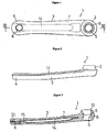
- Figure 1 is a rear view of a particular embodiment of a left side bicycle crank 1 according to the present invention.
- the left crank 1 is made from an aluminum alloy and, as shown in Figure 1, is formed such that its cross section is narrower on the pedal spindle end 4 side where the pedal spindle (not shown) is attached and thicker on the crank spindle end 2 side Where the crank spindle (not shown) is attached.
- a chamfered section 11 is formed along both edges on the back side of the left crank 1.
- a pedal attachment hole 6 for attachment of a pedal spindle (not shown) is formed in the pedal spindle end 4 on the pedal attachment side ofthe left crank 1.
- a crank spindle attachment hole 5 for attaching the left crank 1 to the crank spindle by inserting the spindle into the crank spindle attachment hole 5 is formed at the crank spindle end 2 of the left crank 1. More specifically, a flange 8 protrudes inward from the inner surface of the crank spindle attachment hole 5, and a male serration 9 is provided integrally on the rear surface side of this flange 8.
- the serration 9 has eight teeth, as shown in Figure 1. If there are too few teeth, the strength of the rotational bond will be inadequate. On the other hand, if there are too many teeth the machining will be difficult, the cost will be higher, and there will be a higher incidence of errors in the positioning of indexing in the rotational direction during assembly.
- the portion of the crank spindle attachment hole 5 to the rear of the serration 9 is structured as a centering component (also called a guide component) 10 that is a concentrically tapered hole.
- the centering component 10 is in the form of a cylindrical tapered hole that widens to the rear, and, in this example, it is formed at a taper angle of 2° to 3°.
- the taper surface of the centering component 10 is snugged up against the taper surface of the centering component of the crank spindle (not shown), which accurately aligns the two centers and also links them together integrally and securely.
- a pipe core 7 made from pure aluminum is formed along the pedal spindle end 4 side and the crank spindle end 2 side centering on the crank center 3, wherein the cross sectional structure of the pipe core 7 is shown in Figures 5(a)-(d). More specifically, the cross sectional structure of the pipe core 7 is such that the shape is semicircular on the crank spindle end 2 side, and this shape flattens out to a rectangular shape on the pedal spindle end 4 side. The cross sectional area of the pipe core 7 continuously decreases, and the height is at a minimum at the two ends. In other words, the shape of the pipe core 7 approximates that of a ship hull.
- the weight of the left crank 1 is reduced by the pipe core 7 on the interior of the crank center 3.
- the pipe core 7 also contributes to flexural and other aspects of mechanical stress.
- the metal of the pipe core 7 may be the same as the metal that makes up the left crank 1, but preferably should have as low a specific gravity as possible, be resistant to heat, and be able to withstand the pressure of forging as discussed below.
- the opening 15 communicates with the internal cavity 14 of the pipe core 7, as discussed below.
- the internal cavity 14 is temporarily filled with sand or another filler.
- the filler packed into the pipe core 7 prevents the pipe core 7 from being crushed by the pressure of hot forging.
- the filler need not be taken out as discussed below, and may instead remain packed inside the finished product.
- the left crank 1 may be manufactured by the following method.
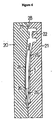
- Figure 6 is a cross sectional view of the molding apparatus during initial casting.
- a melt space 22, into which the molten metal is allowed to flow between the metal mold 20 and the metal mold 21, is demarcated within the metal mold 20 and the metal mold 21.
- the melt space 22 is demarcated in a shape roughly corresponding to the left crank 1, but the melt space 22 is slightly larger to accommodate the shrinkage of the molten metal.
- the pipe core 7 is inserted into the melt space 22.
- the pipe core 7 may be made by baking foamed volcanic glass.
- Figure 7 is an oblique projection of the mold core mold.
- Volcanic glass or another sand-like filler 32 is poured into the internal hole 30 of the pipe core 7.
- the filler 32 may be made of any material that is resistant to the heat of the molten metal and is able to withstand the compression load created by forging (discussed below).
- One of the flattened components 33 is integrally cast and fuses with the molten metal, thus constituting the pedal spindle end 4 of the left crank 1.
- the pipe core 7 is positioned within the melt space 22 as shown in Figure 6.
- spacers 26 made from foamed styrene or the like are used to position the pipe core 7.
- the melt space 22 communicates with a sprue 28 via a runner 27.
- a molten aluminum alloy is poured into the sprue 28, goes through the runner 27, and enters the melt space 22.
- the molten metal applies pressure to the melt space 22 by gravitational force.
- This casting method is a metal mold casting method, also called metal mold gravity casting, in which ordinary casting is performed without any pressure being applied to the molten metal, using only gravitational pressure.
- the casting is subjected to mold forging while the pipe core 7 is still inside the crank billet 29.
- mold forging the casting is placed in a semi-closed metal mold 35 that is used for semi-closed forging, and is hot forged therein.
- Figure 8 is across section of the state when the crank billet 29 has been put into a lower metal mold 36.
- the crank billet 29 is then heated to a specific temperature and placed in the lower metal mold 36, after which pressure is applied from an upper metal mold 37 to perform forging.
- the length, overall thickness, wall thickness, and surface of the cast crank billet 29 are precisely worked, the material of the crank billet 29 is tempered and homogenized, and the mechanical strength is increased. Because the pipe core 7 produced by this hot forging is still inside the crank billet 29 during the forging, the pipe core 7 is not crushed, and its shape is instead preserved.
- the filler 32 may be taken out from the opening 15 by drilling a lower hole in the pedal attachment hole 6 of the crank billet 29.
- the extra portion of the flattened component 33 is also cut off.
- the casting is worked into the shape of the left crank 1 by cutting, grinding, polishing, or other such machining.
Landscapes
- Engineering & Computer Science (AREA)
- Mechanical Engineering (AREA)
- Chemical & Material Sciences (AREA)
- Combustion & Propulsion (AREA)
- Transportation (AREA)
- Molds, Cores, And Manufacturing Methods Thereof (AREA)
- Shafts, Cranks, Connecting Bars, And Related Bearings (AREA)
- Forging (AREA)
Priority Applications (1)
| Application Number | Priority Date | Filing Date | Title |
|---|---|---|---|
| EP03001700A EP1306295B1 (fr) | 1996-12-27 | 1997-12-23 | Pédalier pour bicyclette et son procédé de fabrication |
Applications Claiming Priority (3)
| Application Number | Priority Date | Filing Date | Title |
|---|---|---|---|
| JP358090/96 | 1996-12-27 | ||
| JP35809096 | 1996-12-27 | ||
| JP35809096A JP3248676B2 (ja) | 1996-12-27 | 1996-12-27 | 自転車用クランクとその製造方法 |
Related Child Applications (2)
| Application Number | Title | Priority Date | Filing Date |
|---|---|---|---|
| EP03001700A Division EP1306295B1 (fr) | 1996-12-27 | 1997-12-23 | Pédalier pour bicyclette et son procédé de fabrication |
| EP03001700.8 Division-Into | 2003-01-27 |
Publications (3)
| Publication Number | Publication Date |
|---|---|
| EP0850826A2 true EP0850826A2 (fr) | 1998-07-01 |
| EP0850826A3 EP0850826A3 (fr) | 1999-07-07 |
| EP0850826B1 EP0850826B1 (fr) | 2003-11-19 |
Family
ID=18457496
Family Applications (2)
| Application Number | Title | Priority Date | Filing Date |
|---|---|---|---|
| EP97310475A Expired - Lifetime EP0850826B1 (fr) | 1996-12-27 | 1997-12-23 | Pédalier pour bicyclette et procédé de fabrication |
| EP03001700A Expired - Lifetime EP1306295B1 (fr) | 1996-12-27 | 1997-12-23 | Pédalier pour bicyclette et son procédé de fabrication |
Family Applications After (1)
| Application Number | Title | Priority Date | Filing Date |
|---|---|---|---|
| EP03001700A Expired - Lifetime EP1306295B1 (fr) | 1996-12-27 | 1997-12-23 | Pédalier pour bicyclette et son procédé de fabrication |
Country Status (6)
| Country | Link |
|---|---|
| US (2) | US6227070B1 (fr) |
| EP (2) | EP0850826B1 (fr) |
| JP (1) | JP3248676B2 (fr) |
| CN (1) | CN1093813C (fr) |
| DE (2) | DE69735245T2 (fr) |
| TW (1) | TW340103B (fr) |
Cited By (4)
| Publication number | Priority date | Publication date | Assignee | Title |
|---|---|---|---|---|
| US6227070B1 (en) * | 1996-12-27 | 2001-05-08 | Shimano, Inc. | Bicycle crank and method for manufacturing same |
| EP1270394A1 (fr) * | 2001-06-27 | 2003-01-02 | Campagnolo Srl | Pédalier pour bicyclette et procédé de fabrication |
| EP1270393A1 (fr) * | 2001-06-27 | 2003-01-02 | Campagnolo S.R.L. | Pédalier pour bicyclette et procédé de fabrication |
| EP1806188A1 (fr) * | 2006-01-10 | 2007-07-11 | Yu, Chai-chi | Moule et procédé de fabrication d'une manivelle |
Families Citing this family (18)
| Publication number | Priority date | Publication date | Assignee | Title |
|---|---|---|---|---|
| JP3248675B2 (ja) * | 1996-12-27 | 2002-01-21 | 株式会社シマノ | 自転車用クランクの製造方法 |
| US6266990B1 (en) * | 2000-09-06 | 2001-07-31 | William Blair Shook | Method for integrally manufacturing an one-piece forged hollow crank of a bicycle |
| US6508002B1 (en) * | 2000-11-22 | 2003-01-21 | Douglas Chiang | Bicycle crank arm and method of making same |
| ITTO20010782A1 (it) * | 2001-08-03 | 2003-02-03 | Campagnolo Srl | Procedimento per la produzione di una pedivella per bicicletta. |
| JP2003103330A (ja) * | 2001-09-27 | 2003-04-08 | Asahi Tec Corp | 鍛造品製造方法、鍛造品製造装置、及びプリフォーム鍛造材 |
| US6612033B1 (en) * | 2002-03-15 | 2003-09-02 | Cheng-Xun Jiang | Method for making hollow bicycle cranks |
| EP1350714A1 (fr) * | 2002-03-19 | 2003-10-08 | Campagnolo Srl | Bras de manivelle d'une bicyclette et procédé de fabrication |
| US20040200314A1 (en) | 2003-04-12 | 2004-10-14 | Frank Hermansen | Bicycle crank arm |
| JP2005289166A (ja) * | 2004-03-31 | 2005-10-20 | Sumitomo Metal Ind Ltd | 自転車用クランクとその製造方法 |
| GB2427159B (en) * | 2005-06-14 | 2007-05-02 | Ourway Engineering Co Ltd | A method for manufacturing an open hollow bicycle crank |
| US20070186718A1 (en) * | 2006-02-13 | 2007-08-16 | Douglas Chiang | Bicycle cranks composed of composite material and metal parts and method for making the same |
| US20070295157A1 (en) * | 2006-06-27 | 2007-12-27 | Specialized Bicycle Components, Inc. | Crankset assembly for a bicycle |
| FR2921574B1 (fr) * | 2007-09-28 | 2010-04-16 | Sifcor | Procede de fabrication de pieces forgees creuses et pieces ainsi obtenues |
| FR2958193B1 (fr) * | 2010-04-06 | 2012-06-29 | Saint Jean Ind | Procede de fabrication de pieces forgees en alliage leger incorporant des sections pleines ou tirees d'epaisseur |
| US9387534B2 (en) * | 2014-08-29 | 2016-07-12 | Zf Friedrichshafen Ag | Control arm and a method for forming the same |
| CN106741552A (zh) * | 2016-12-23 | 2017-05-31 | 鼎镁(昆山)新材料科技有限公司 | 交通工具用齿盘异材组合结构改良 |
| CN109572911A (zh) * | 2018-11-29 | 2019-04-05 | 余其越 | 一种自行车中空曲柄轴杆组件及其制造方法 |
| CN115891216A (zh) * | 2022-12-30 | 2023-04-04 | 厦门碳帝复合材料科技有限公司 | 一种利用水溶性砂芯模成型碳纤维曲柄的方法及其产品 |
Citations (5)
| Publication number | Priority date | Publication date | Assignee | Title |
|---|---|---|---|---|
| JPS487948U (fr) | 1971-06-09 | 1973-01-29 | ||
| JPS5893554A (ja) | 1981-11-30 | 1983-06-03 | Takeshi Arai | 軽合金自転車クランクの製造方法 |
| JPS61131391U (fr) | 1985-02-04 | 1986-08-16 | ||
| JPH0218652A (ja) | 1988-07-07 | 1990-01-22 | Kansai Nippon Denki Software Kk | データ集信方式 |
| JPH05116670A (ja) | 1991-10-29 | 1993-05-14 | Shimano Inc | 連動杆 |
Family Cites Families (35)
| Publication number | Priority date | Publication date | Assignee | Title |
|---|---|---|---|---|
| US2070589A (en) * | 1933-07-04 | 1937-02-16 | Forgeage Electr Giacchino Sa | Process of forging hollow metal blanks |
| US2350468A (en) * | 1941-11-04 | 1944-06-06 | Murray Ohio Mfg Co | Bicycle crank hanger assembly |
| FR980071A (fr) * | 1948-12-09 | 1951-05-08 | Masson Ets | Perfectionnements aux manivelles de pédalier pour cycles et autres |
| FR981600A (fr) * | 1948-12-27 | 1951-05-28 | Manivelle pour pédaliers de cycles ou autres et son procédé de labrication | |
| FR982352A (fr) * | 1949-02-24 | 1951-06-11 | Pierre Lyotard Ets | Manivelle en deux éléments rapportés pour bicyclettes, tandems on similaires |
| US3786543A (en) * | 1972-04-26 | 1974-01-22 | Nippon Miniature Bearing Co Lt | Method of producing rotating joint member by casting |
| JPS5116670A (en) * | 1973-09-10 | 1976-02-10 | Sakai Chemical Industry Co | 44 amino 3*55 jichikan 1*2*44 toriazoorurui no seizohoho |
| US4186586A (en) * | 1975-07-18 | 1980-02-05 | Nippon Gakki Seizo Kabushiki Kaisha | Billet and process for producing a tubular body by forced plastic deformation |
| FR2443610A1 (fr) * | 1978-12-04 | 1980-07-04 | Aerospatiale | Procede pour l'agencement d'un organe de liaison a une extremite d'une bielle de commande et bielle comportant un tel agencement |
| FR2446180A1 (fr) * | 1979-01-15 | 1980-08-08 | Aerospatiale | Procede pour la realisation d'une bielle de commande ou de transmission d'efforts et bielle ainsi obtenue |
| DE3004575A1 (de) * | 1980-02-08 | 1981-08-13 | Sigri Elektrographit Gmbh, 8901 Meitingen | Pleuelstange aus verbundwerkstoff |
| USD265812S (en) * | 1980-05-27 | 1982-08-17 | Kastan B Linn | Crank arm for a bicycle crank assembly |
| US4465392A (en) * | 1981-06-12 | 1984-08-14 | The United States Of America As Represented By The Secretary Of The Air Force | Thermally isolated structural support link |
| JPS6013761A (ja) | 1983-07-05 | 1985-01-24 | Yamanouchi Pharmaceut Co Ltd | 新規なピリジルエ−テル誘導体 |
| JPS6113191U (ja) | 1984-06-27 | 1986-01-25 | 三菱重工業株式会社 | 管内清掃器 |
| JPS61121391A (ja) | 1984-11-16 | 1986-06-09 | 松下電器産業株式会社 | 印刷配線板 |
| JPS61131391A (ja) | 1984-11-29 | 1986-06-19 | 松下電器産業株式会社 | 電波シ−ル装置 |
| JPS61150691A (ja) | 1984-12-21 | 1986-07-09 | Nissan Motor Co Ltd | 交流モ−タ制御装置 |
| DE3763809D1 (de) * | 1986-10-31 | 1990-08-23 | Look Sa | Kurbel fuer tretlager eines fahrrads. |
| US4841801A (en) * | 1987-03-25 | 1989-06-27 | Trw Inc. | Connecting rod |
| US5027497A (en) * | 1989-04-06 | 1991-07-02 | Tokyo Rope Mfg. Co., Ltd. | Method for forming fixing end portion of composite rope and composite rope |
| US5125288A (en) | 1991-01-22 | 1992-06-30 | Amiet Alick G | Arcuate bicyle crank lever apparatus |
| US5197353A (en) * | 1991-07-31 | 1993-03-30 | John Trenerry | Crank and spider assembly for bicycle |
| US5179873A (en) | 1991-09-09 | 1993-01-19 | Ocean State International, Inc. | Bicycle crank assembly |
| ATE150712T1 (de) * | 1993-10-06 | 1997-04-15 | Abb Daimler Benz Transp | Verbundbauteil als zug-druck-stange für schienenfahrzeuge |
| US5623856A (en) * | 1995-05-31 | 1997-04-29 | Durham; Roger O. | Bicycle crank arm with internal flange |
| US5609070A (en) * | 1995-08-01 | 1997-03-11 | Lin; King-Chen | Crank cover assembly for a bicycle |
| JP3526683B2 (ja) * | 1995-08-04 | 2004-05-17 | 株式会社シマノ | 自転車用クランク組立体、自転車用組立工具および自転車組立用補助具 |
| USD384603S (en) * | 1996-08-21 | 1997-10-07 | Dotek Corporation | Crank for a bicycle |
| USD401539S (en) * | 1996-09-18 | 1998-11-24 | Cannondale Corporation | Crankarm for a bicycle |
| US5904072A (en) * | 1996-12-20 | 1999-05-18 | Shimano Inc. | Bicycle crank arm |
| JP3248675B2 (ja) * | 1996-12-27 | 2002-01-21 | 株式会社シマノ | 自転車用クランクの製造方法 |
| JP3248676B2 (ja) * | 1996-12-27 | 2002-01-21 | 株式会社シマノ | 自転車用クランクとその製造方法 |
| JP3149374B2 (ja) * | 1996-12-27 | 2001-03-26 | 株式会社シマノ | 自転車用中空クランクとその製造方法 |
| US5907896A (en) * | 1997-09-10 | 1999-06-01 | Tseng; Shao-Chien | Method for bending forging artistic metallic pipes |
-
1996
- 1996-12-27 JP JP35809096A patent/JP3248676B2/ja not_active Expired - Fee Related
-
1997
- 1997-12-18 US US08/993,449 patent/US6227070B1/en not_active Expired - Lifetime
- 1997-12-23 EP EP97310475A patent/EP0850826B1/fr not_active Expired - Lifetime
- 1997-12-23 EP EP03001700A patent/EP1306295B1/fr not_active Expired - Lifetime
- 1997-12-23 DE DE69735245T patent/DE69735245T2/de not_active Expired - Lifetime
- 1997-12-23 DE DE69726249T patent/DE69726249T2/de not_active Expired - Lifetime
- 1997-12-26 TW TW086119775A patent/TW340103B/zh active
- 1997-12-29 CN CN97125947A patent/CN1093813C/zh not_active Expired - Fee Related
-
1999
- 1999-03-03 US US09/262,138 patent/US6195894B1/en not_active Expired - Fee Related
Patent Citations (5)
| Publication number | Priority date | Publication date | Assignee | Title |
|---|---|---|---|---|
| JPS487948U (fr) | 1971-06-09 | 1973-01-29 | ||
| JPS5893554A (ja) | 1981-11-30 | 1983-06-03 | Takeshi Arai | 軽合金自転車クランクの製造方法 |
| JPS61131391U (fr) | 1985-02-04 | 1986-08-16 | ||
| JPH0218652A (ja) | 1988-07-07 | 1990-01-22 | Kansai Nippon Denki Software Kk | データ集信方式 |
| JPH05116670A (ja) | 1991-10-29 | 1993-05-14 | Shimano Inc | 連動杆 |
Cited By (7)
| Publication number | Priority date | Publication date | Assignee | Title |
|---|---|---|---|---|
| US6227070B1 (en) * | 1996-12-27 | 2001-05-08 | Shimano, Inc. | Bicycle crank and method for manufacturing same |
| EP1270394A1 (fr) * | 2001-06-27 | 2003-01-02 | Campagnolo Srl | Pédalier pour bicyclette et procédé de fabrication |
| EP1270393A1 (fr) * | 2001-06-27 | 2003-01-02 | Campagnolo S.R.L. | Pédalier pour bicyclette et procédé de fabrication |
| US7000499B2 (en) | 2001-06-27 | 2006-02-21 | Campagnolo, S.R.L. | Bicycle crank and method for manufacturing said crank |
| US7013753B2 (en) | 2001-06-27 | 2006-03-21 | Campagnolo S.R.L. | Bicycle crank and method for manufacturing said crank |
| EP1669285A3 (fr) * | 2001-06-27 | 2009-02-18 | CAMPAGNOLO S.r.l. | Pédalier pour bicyclette et procédé de fabrication |
| EP1806188A1 (fr) * | 2006-01-10 | 2007-07-11 | Yu, Chai-chi | Moule et procédé de fabrication d'une manivelle |
Also Published As
| Publication number | Publication date |
|---|---|
| EP1306295A3 (fr) | 2004-01-14 |
| EP0850826B1 (fr) | 2003-11-19 |
| CN1093813C (zh) | 2002-11-06 |
| EP0850826A3 (fr) | 1999-07-07 |
| CN1186749A (zh) | 1998-07-08 |
| DE69735245D1 (de) | 2006-04-20 |
| EP1306295B1 (fr) | 2006-02-15 |
| JP3248676B2 (ja) | 2002-01-21 |
| DE69726249D1 (de) | 2003-12-24 |
| US6227070B1 (en) | 2001-05-08 |
| JPH10181663A (ja) | 1998-07-07 |
| US6195894B1 (en) | 2001-03-06 |
| EP1306295A2 (fr) | 2003-05-02 |
| TW340103B (en) | 1998-09-11 |
| DE69735245T2 (de) | 2006-11-23 |
| DE69726249T2 (de) | 2004-09-09 |
Similar Documents
| Publication | Publication Date | Title |
|---|---|---|
| EP0850826B1 (fr) | Pédalier pour bicyclette et procédé de fabrication | |
| EP0850825B1 (fr) | Bras de manivelle d'une bicyclette et procédé de fabrication | |
| EP0850827B1 (fr) | Pédalier pour bicyclette et son procédé de fabrication | |
| US20040200314A1 (en) | Bicycle crank arm | |
| EP1350714A1 (fr) | Bras de manivelle d'une bicyclette et procédé de fabrication | |
| US5241737A (en) | Method of making a composite casting | |
| JPH05118360A (ja) | ブレーキキヤリパー | |
| US5524698A (en) | Method of making a one-body precision cast metal golf club head | |
| JP2003502198A (ja) | 自動車用ホイール | |
| JPS63268551A (ja) | 軽合金鋳物 | |
| JP3507804B2 (ja) | 自転車用クランク | |
| JP4210570B2 (ja) | 鋳造方法及び鋳造部品 | |
| JPS61172666A (ja) | 繊維強化筒状部材の製造方法 | |
| JPH082477B2 (ja) | 鋳造に使用される中子 | |
| JP3507803B2 (ja) | 自転車用クランク | |
| JPH0159063B2 (fr) | ||
| GB2246972A (en) | Method of producing a composite casting | |
| JPH08215351A (ja) | 一体精密鋳造金属ゴルフクラブヘッドの製造方法 |
Legal Events
| Date | Code | Title | Description |
|---|---|---|---|
| PUAI | Public reference made under article 153(3) epc to a published international application that has entered the european phase |
Free format text: ORIGINAL CODE: 0009012 |
|
| 17P | Request for examination filed |
Effective date: 19980115 |
|
| AK | Designated contracting states |
Kind code of ref document: A2 Designated state(s): DE FR IT |
|
| AX | Request for extension of the european patent |
Free format text: AL;LT;LV;MK;RO;SI |
|
| PUAL | Search report despatched |
Free format text: ORIGINAL CODE: 0009013 |
|
| AK | Designated contracting states |
Kind code of ref document: A3 Designated state(s): AT BE CH DE DK ES FI FR GB GR IE IT LI LU MC NL PT SE |
|
| AX | Request for extension of the european patent |
Free format text: AL;LT;LV;MK;RO;SI |
|
| AKX | Designation fees paid |
Free format text: DE FR IT |
|
| 17Q | First examination report despatched |
Effective date: 20020923 |
|
| GRAH | Despatch of communication of intention to grant a patent |
Free format text: ORIGINAL CODE: EPIDOS IGRA |
|
| GRAS | Grant fee paid |
Free format text: ORIGINAL CODE: EPIDOSNIGR3 |
|
| GRAA | (expected) grant |
Free format text: ORIGINAL CODE: 0009210 |
|
| AK | Designated contracting states |
Kind code of ref document: B1 Designated state(s): DE FR IT |
|
| REF | Corresponds to: |
Ref document number: 69726249 Country of ref document: DE Date of ref document: 20031224 Kind code of ref document: P |
|
| ET | Fr: translation filed | ||
| PLBE | No opposition filed within time limit |
Free format text: ORIGINAL CODE: 0009261 |
|
| STAA | Information on the status of an ep patent application or granted ep patent |
Free format text: STATUS: NO OPPOSITION FILED WITHIN TIME LIMIT |
|
| 26N | No opposition filed |
Effective date: 20040820 |
|
| PGFP | Annual fee paid to national office [announced via postgrant information from national office to epo] |
Ref country code: FR Payment date: 20111219 Year of fee payment: 15 |
|
| PGFP | Annual fee paid to national office [announced via postgrant information from national office to epo] |
Ref country code: IT Payment date: 20121219 Year of fee payment: 16 |
|
| REG | Reference to a national code |
Ref country code: FR Ref legal event code: ST Effective date: 20130830 |
|
| PG25 | Lapsed in a contracting state [announced via postgrant information from national office to epo] |
Ref country code: FR Free format text: LAPSE BECAUSE OF NON-PAYMENT OF DUE FEES Effective date: 20130102 |
|
| PGFP | Annual fee paid to national office [announced via postgrant information from national office to epo] |
Ref country code: DE Payment date: 20141216 Year of fee payment: 18 |
|
| PG25 | Lapsed in a contracting state [announced via postgrant information from national office to epo] |
Ref country code: IT Free format text: LAPSE BECAUSE OF NON-PAYMENT OF DUE FEES Effective date: 20131231 |
|
| PG25 | Lapsed in a contracting state [announced via postgrant information from national office to epo] |
Ref country code: IT Free format text: LAPSE BECAUSE OF NON-PAYMENT OF DUE FEES Effective date: 20131223 |
|
| REG | Reference to a national code |
Ref country code: DE Ref legal event code: R119 Ref document number: 69726249 Country of ref document: DE |
|
| PG25 | Lapsed in a contracting state [announced via postgrant information from national office to epo] |
Ref country code: DE Free format text: LAPSE BECAUSE OF NON-PAYMENT OF DUE FEES Effective date: 20160701 |