EP0851164A2 - System zur Steuerung eines pulsbreitenmodulierten Elektromagnetventils - Google Patents
System zur Steuerung eines pulsbreitenmodulierten Elektromagnetventils Download PDFInfo
- Publication number
- EP0851164A2 EP0851164A2 EP97116582A EP97116582A EP0851164A2 EP 0851164 A2 EP0851164 A2 EP 0851164A2 EP 97116582 A EP97116582 A EP 97116582A EP 97116582 A EP97116582 A EP 97116582A EP 0851164 A2 EP0851164 A2 EP 0851164A2
- Authority
- EP
- European Patent Office
- Prior art keywords
- valve
- during
- stage
- signals
- signal
- Prior art date
- Legal status (The legal status is an assumption and is not a legal conclusion. Google has not performed a legal analysis and makes no representation as to the accuracy of the status listed.)
- Withdrawn
Links
Images

Classifications
-
- F—MECHANICAL ENGINEERING; LIGHTING; HEATING; WEAPONS; BLASTING
- F16—ENGINEERING ELEMENTS AND UNITS; GENERAL MEASURES FOR PRODUCING AND MAINTAINING EFFECTIVE FUNCTIONING OF MACHINES OR INSTALLATIONS; THERMAL INSULATION IN GENERAL
- F16K—VALVES; TAPS; COCKS; ACTUATING-FLOATS; DEVICES FOR VENTING OR AERATING
- F16K31/00—Actuating devices; Operating means; Releasing devices
- F16K31/02—Actuating devices; Operating means; Releasing devices electric; magnetic
- F16K31/06—Actuating devices; Operating means; Releasing devices electric; magnetic using a magnet, e.g. diaphragm valves, cutting off by means of a liquid
- F16K31/0675—Electromagnet aspects, e.g. electric supply therefor
-
- F—MECHANICAL ENGINEERING; LIGHTING; HEATING; WEAPONS; BLASTING
- F16—ENGINEERING ELEMENTS AND UNITS; GENERAL MEASURES FOR PRODUCING AND MAINTAINING EFFECTIVE FUNCTIONING OF MACHINES OR INSTALLATIONS; THERMAL INSULATION IN GENERAL
- F16K—VALVES; TAPS; COCKS; ACTUATING-FLOATS; DEVICES FOR VENTING OR AERATING
- F16K31/00—Actuating devices; Operating means; Releasing devices
- F16K31/02—Actuating devices; Operating means; Releasing devices electric; magnetic
- F16K31/06—Actuating devices; Operating means; Releasing devices electric; magnetic using a magnet, e.g. diaphragm valves, cutting off by means of a liquid
- F16K31/0686—Braking, pressure equilibration, shock absorbing
-
- Y—GENERAL TAGGING OF NEW TECHNOLOGICAL DEVELOPMENTS; GENERAL TAGGING OF CROSS-SECTIONAL TECHNOLOGIES SPANNING OVER SEVERAL SECTIONS OF THE IPC; TECHNICAL SUBJECTS COVERED BY FORMER USPC CROSS-REFERENCE ART COLLECTIONS [XRACs] AND DIGESTS
- Y10—TECHNICAL SUBJECTS COVERED BY FORMER USPC
- Y10T—TECHNICAL SUBJECTS COVERED BY FORMER US CLASSIFICATION
- Y10T137/00—Fluid handling
- Y10T137/0318—Processes
Definitions
- This invention relates to a control system for pulse width modulation-operated (PWM signals) solenoid valves comprising a seal seat, a valving or sealing member, elastic means operating on said valving member to tend to maintain said member on the seal seat, and a solenoid which, when energized, withdraws the valving member from the seal seat against the action of the elastic means.
- PWM signals pulse width modulation-operated
- the system is of the type in which the valve opening pulses are provided by a microcontroller or the like, which amplitude-modulates the width of said pulses on the basis of the user-set flow rate of the fluid (generally fuel gas) passing through the valve.
- a microcontroller or the like which amplitude-modulates the width of said pulses on the basis of the user-set flow rate of the fluid (generally fuel gas) passing through the valve.
- the sealing member comprises an elastomer part.
- the solenoid When the solenoid is de-energized, the spring violently urges the sealing member against the relative seat.
- the elastomer part hence absorbs all the kinetic energy possessed by the relative sealing member following the thrust of the spring, the impact against the seal seat being such as to produce permanent deformation of the elastomer material with the passage of time, so limiting the useful life of the solenoid valve, especially when frequent switching is necessary, as in the case of control by PWM signals.
- Italian patent application MI95A001856 filed on 01/03/95 in the name of the present applicant describes a system for remedying this problem.
- a force counteracting the spring is applied to the valving member when moving towards the seal seat, to reduce the impact energy between the relative sealing member and the relative seat.
- a feedback circuit is provided which carries the information relative to the start of the actuator movement to a microprocessor to operate the braking force.
- This known system eliminates (or reduces) the effect of the impact against the seat, but includes the use of a suitable feedback circuit.
- it does not also allow the valving member to be damped during the opening stage, with consequent annoying noise when this member collides on termination of opening, together with vibration and hence noise induced in the structures connected to the valve, and lack of perfect linearization of flow control (ie the flow does not increase linearly with increased duty cycle).
- An object of the present invention is to provide a system which not only enables the results obtained with the known solution to be improved, but also enables new results to be achieved by on the one hand eliminating noise and vibration during both opening and closure, and on the other hand achieving perfect flow linearization.
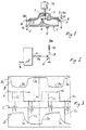
- valves to which the invention relates are two-state shutoff valves (open/closed). They comprise ( Figure 1) a body 1 provided with an inlet 2 and an outlet 3. In the body 1 there is provided a seal seat 4 to be closed by a sealing member 5 of elastomer material or the like.
- the member 5 is rigid with a moving core 6 (the two forming the valve moving member), on it there acting in one direction a return spring 7 for urging it against the seal seat 4 to obtain the normally "closed” state of the valve when at rest.
- the moving core 6 is mounted slidable within a stationary solenoid or coil 7A, which when energized causes the sealing member 5 to withdraw against the action of the spring, to achieve the valve "open” state in operation.
- the coil or solenoid of the solenoid valve is connected ( Figure 2) to a d.c. voltage source V DC in series with a static switch 8 represented by way of example as a transistor with its emitter connected to earth.
- the base of the transistor 8 is connected via a resistor R B to a microprocessor nP which on the basis of input signals which reach it via one or more lines K controls the transistor 8 and hence the valve with PWM (pulse width modulated) signals, the duty cycle of which depends on the signal or signals originating from the line or lines K.
- PWM pulse width modulated
- the signals along the lines K can relate to the position of a knob (not shown) which the user operates to vary the flow of gas through the valve towards a conventional burner of a gas hob or cooker.
- Signals are taken from the points A and D of the circuit of Figure 2. Other signals are taken ( Figure 1) from the accelerometer C and from the point B of the circuit of the infrared receiver device.
- the signal B is inversely proportional to the valve opening; in this respect when the valve is open there is maximum passage of infrared radiation through the valve so that the impedance of the receiver device 11 is low, as is the signal B.
- the signal B is instead high with the valve closed, when no infrared radiation reaches the receiver device 11.
- the portions B1 and B2 of the curve B represent the closed state and the open state respectively.
- the signal A represents the PWM signal (width modulated signal) applied to the static switch 8 and is hence the signal for operating the valve (or its coil).
- portion A1 When it is high (portions A1) the static switch conducts and hence the coil 7A is energized, with consequent opening of the solenoid valve, which is maintained in this state (in this respect it should be noted that the valve requires a certain time, even though very short, to move from one state to the other).
- portion A2 When it is low (portions A2) the static switch is inhibited, the coil 7A is de-energized and the valve moves to its closed state, which it maintains until the new pulse A1.
- the signal C is that obtained from the accelerometer, which measures the "acceleration" generated by the end-of-travel impact both of opening and of closure of the valve moving member (5+6).
- the impacts or vibrations are indicative of the noise of the valve and of the structures connected thereto.
- the curve D shows the signal variation at the static switch 8.
- the portions D1 and D2 represent this variation during valve closure and opening respectively, the remaining portions indicating the signal with the valve open and closed.
- the portions D1 and D2 represent the de-energized and energized state of the coil.
- the opening and closure stages of the solenoid valve ie the movement of the relative mobile member (5+6), are modulated in a certain sense by controlling its coil or solenoid by suitable braking action.
- a succession or train of pulses results in active interventions of the coil or solenoid 7A such as to oppose the action of the return spring 7, whereas during the opening stage, in which the coil 7A is energized, this train or succession of pulses are in a sense "off-cut" from the high PWM signal; with the intervals between one pulse and the next, this pulse train or succession results in a reduction in the attraction force of the coil or solenoid, hence enabling the spring 7 to exert a greater counteracting and hence braking action.
- Figures 5 and 6 represent the signals as a function of time, obtained at the points A, B, C, D of Figures 1 and 2, but using the control system of the invention.
- these signals are identified by the same letters but with the addition of an asterisk (ie A*, B*, C*, D*) to distinguish them from the signals obtained at the same points with the traditional control system shown in Figure 3.
- the signal comprises or is formed from a succession or train of pulses T (which can be of equal or different duration) off-cut from the high PWM signal.
- the initial pulse T1 preferably has a longer duration than the subsequent pulses T, which can be equal.
- the invention therefore reduces the motor effect of the coil 7A by the pulse train or succession, which with the intervals ⁇ between the individual pulses T determines moments of absence of the signal controlling the static switch 8, and hence in practice moments of absence of power to the coil 7A.
- this stage is defined by the portions A 2 which are substantially flat.
- this stage (A 2 *) is divided into two parts, namely a valve "CLOSURE” part followed by a flat valve closed part.
- the "CLOSURE" part is identified by a succession or train of pulses P (equal or different in duration) which operate in such a sense as to energize the coil 7A so that this counteracts the closure action which the spring 7 exerts on the valve.
- P pulses
- vibration source of noise
- the signal D* differs considerably from the signal D by the modulation introduced by the pulse trains T and P (both imposed and off-cut).
- valve throughput is a linear function of the duty cycle instead of non-linear as within the range between 20% and 25% of the duty cycle of the traditional system.
- the pulse trains and their format are provided by the microprocessor nP implemented on the basis of experimental data obtained for each type of valve, for example, for a given value of the duty cycle.
Landscapes
- Engineering & Computer Science (AREA)
- General Engineering & Computer Science (AREA)
- Mechanical Engineering (AREA)
- Physics & Mathematics (AREA)
- Electromagnetism (AREA)
- Magnetically Actuated Valves (AREA)
Applications Claiming Priority (2)
| Application Number | Priority Date | Filing Date | Title |
|---|---|---|---|
| ITMI962761 | 1996-12-30 | ||
| IT96MI002761A IT1289547B1 (it) | 1996-12-30 | 1996-12-30 | Sistema di controllo di elettrovalvole azionate a modulazione in larghezza di impulsi |
Publications (2)
| Publication Number | Publication Date |
|---|---|
| EP0851164A2 true EP0851164A2 (de) | 1998-07-01 |
| EP0851164A3 EP0851164A3 (de) | 1999-05-12 |
Family
ID=11375506
Family Applications (1)
| Application Number | Title | Priority Date | Filing Date |
|---|---|---|---|
| EP97116582A Withdrawn EP0851164A3 (de) | 1996-12-30 | 1997-09-24 | System zur Steuerung eines pulsbreitenmodulierten Elektromagnetventils |
Country Status (3)
| Country | Link |
|---|---|
| US (1) | US6056000A (de) |
| EP (1) | EP0851164A3 (de) |
| IT (1) | IT1289547B1 (de) |
Cited By (9)
| Publication number | Priority date | Publication date | Assignee | Title |
|---|---|---|---|---|
| EP1130300A1 (de) | 2000-02-29 | 2001-09-05 | Whirlpool Corporation | Verfahren zur Steuerung von pulsbreitenmodulations- gesteuerten Ventilen |
| WO2007005424A1 (en) * | 2005-07-05 | 2007-01-11 | Emcon Technologies Llc | Velocity control of exhaust valve actuation |
| WO2010141241A1 (en) * | 2009-06-05 | 2010-12-09 | Baxter International Inc. | Solenoid pinch valve apparatus and method for medical fluid applications having reduced noise production |
| EP2527061A1 (de) * | 2011-05-27 | 2012-11-28 | Siemens VAI Metals Technologies GmbH | Verfahren zur Kühlung eines metallischen Strangs und Schaltventil zum intermittierenden Öffnen und Schließen eines Volumenstroms eines Kühlmediums |
| WO2014124507A1 (en) * | 2013-02-15 | 2014-08-21 | Whirlpool S.A. | Method for actuating valve and system for actuating valve for multi-suction alternative compressor |
| WO2017042059A1 (de) * | 2015-09-07 | 2017-03-16 | Primetals Technologies Austria GmbH | Sekundärkühlung eines strangs in einer stranggiessanlage |
| CN109765943A (zh) * | 2019-01-14 | 2019-05-17 | 东北大学 | 一种加热炉燃料阀门脉冲优化控制装置与方法 |
| WO2022157215A1 (de) * | 2021-01-22 | 2022-07-28 | Amazonen-Werke H. Dreyer SE & Co. KG | Verfahren zum ansteuern eines zur durchflussmengensteuerung eingesetzten magnetventils einer landwirtschaftlichen ausbringmaschine |
| US11867314B2 (en) | 2018-05-31 | 2024-01-09 | Fas Medic S.A. | Method and apparatus for energising a solenoid of a valve assembly |
Families Citing this family (14)
| Publication number | Priority date | Publication date | Assignee | Title |
|---|---|---|---|---|
| US6493204B1 (en) * | 1999-07-09 | 2002-12-10 | Kelsey-Hayes Company | Modulated voltage for a solenoid valve |
| CA2461390C (en) | 2001-09-28 | 2007-11-20 | Manitowoc Foodservice Companies, Inc. | Beverage dispenser and automatic shut-off valve |
| CN100458614C (zh) * | 2006-04-06 | 2009-02-04 | 台湾樱花股份有限公司 | 热水器的电磁阀控制电路及电磁阀控制方法 |
| US7762521B2 (en) * | 2006-05-23 | 2010-07-27 | Southwest Research Institute | Semi-active compressor valve |
| EP2020572B1 (de) * | 2007-07-31 | 2012-12-26 | Sit la Precisa S.p.a. | Automatische Vorrichtung zur Zündung und Steuerung eines Gasgeräts und entsprechendes Antriebsverfahren |
| CN102076949B (zh) * | 2008-08-01 | 2013-06-05 | 三菱电机株式会社 | 阀控制装置和阀装置 |
| DE102008047632A1 (de) * | 2008-09-17 | 2010-03-25 | Knorr-Bremse Systeme für Nutzfahrzeuge GmbH | Feststellbremsanlage |
| US10240785B2 (en) * | 2010-01-28 | 2019-03-26 | Noritz Corporation | Driving method for solenoid valve, solenoid valve driving apparatus, and combustion apparatus including same |
| KR101981670B1 (ko) * | 2012-12-21 | 2019-05-24 | 삼성전자주식회사 | 가스 오븐 |
| US20150167589A1 (en) * | 2013-12-13 | 2015-06-18 | Hyundai Motor Company | Method and apparatus for controlling high pressure shut-off valve |
| JP6406574B2 (ja) * | 2014-09-08 | 2018-10-17 | 日本電産トーソク株式会社 | 電磁弁制御装置、コントロールバルブ装置、および電磁弁制御方法 |
| DE102016103249A1 (de) * | 2016-02-24 | 2017-08-24 | Truma Gerätetechnik GmbH & Co. KG | Gasventil und Verfahren zu seiner Ansteuerung |
| JP7427357B2 (ja) * | 2017-06-07 | 2024-02-05 | 株式会社堀場エステック | 流体制御装置、制御プログラム、及び、制御方法 |
| EP3412946A1 (de) * | 2017-06-09 | 2018-12-12 | Andreas Stihl AG & Co. KG | Verfahren zur ansteuerung eines elektromagnetischen ventils und elektromagnetisches ventil |
Family Cites Families (7)
| Publication number | Priority date | Publication date | Assignee | Title |
|---|---|---|---|---|
| JPS5772306A (en) * | 1980-10-23 | 1982-05-06 | Nippon Gakki Seizo Kk | Plunger driving circuit |
| US4726389A (en) * | 1986-12-11 | 1988-02-23 | Aisan Kogyo Kabushiki Kaisha | Method of controlling injector valve |
| JPH0430403A (ja) * | 1990-05-25 | 1992-02-03 | Nisca Corp | 直流ソレノイドの駆動方法 |
| US5381297A (en) * | 1993-06-18 | 1995-01-10 | Siemens Automotive L.P. | System and method for operating high speed solenoid actuated devices |
| IT1277534B1 (it) * | 1995-09-01 | 1997-11-11 | Whirlpool Italia S P A | Metodo e circuito per aumentare la durata di vita delle elettrovalvole |
| DE19600351A1 (de) * | 1996-01-08 | 1997-07-10 | Kromschroeder Ag G | Mangetventil, insbesondere für brennerbetriebene Haushalts-Heizgeräte |
| DE19606525A1 (de) * | 1996-02-22 | 1997-08-28 | Kammerer Gmbh M | Verfahren und Anordnung zum Schalten einer Endstufe zur Ansteuerung einer elektromagnetischen Last, insbesondere für Heizwassersteuereinheiten in Kraftfahrzeugen |
-
1996
- 1996-12-30 IT IT96MI002761A patent/IT1289547B1/it active IP Right Grant
-
1997
- 1997-09-24 EP EP97116582A patent/EP0851164A3/de not_active Withdrawn
- 1997-12-29 US US08/999,365 patent/US6056000A/en not_active Expired - Fee Related
Non-Patent Citations (1)
| Title |
|---|
| None |
Cited By (19)
| Publication number | Priority date | Publication date | Assignee | Title |
|---|---|---|---|---|
| EP1130300A1 (de) | 2000-02-29 | 2001-09-05 | Whirlpool Corporation | Verfahren zur Steuerung von pulsbreitenmodulations- gesteuerten Ventilen |
| WO2007005424A1 (en) * | 2005-07-05 | 2007-01-11 | Emcon Technologies Llc | Velocity control of exhaust valve actuation |
| US7243623B2 (en) | 2005-07-05 | 2007-07-17 | Arvin Technologies, Inc. | Velocity control of exhaust valve actuation |
| CN101198773B (zh) * | 2005-07-05 | 2010-12-08 | 排放控制技术有限公司 | 排气阀致动的速度控制 |
| US9782577B2 (en) | 2009-06-05 | 2017-10-10 | Baxter International Inc. | Solenoid pinch valve apparatus and method for medical fluid applications having reduced noise production |
| WO2010141241A1 (en) * | 2009-06-05 | 2010-12-09 | Baxter International Inc. | Solenoid pinch valve apparatus and method for medical fluid applications having reduced noise production |
| US9435459B2 (en) | 2009-06-05 | 2016-09-06 | Baxter International Inc. | Solenoid pinch valve apparatus and method for medical fluid applications having reduced noise production |
| WO2012163878A1 (de) * | 2011-05-27 | 2012-12-06 | Siemens Vai Metals Technologies Gmbh | Verfahren zur kühlung eines metallischen strangs und schaltventil zum intermittierenden öffnen und schliessen eines volumenstroms eines kühlmediums |
| CN103764315A (zh) * | 2011-05-27 | 2014-04-30 | 西门子Vai金属科技有限责任公司 | 用于对金属的连铸坯进行冷却的方法以及用于间歇地打开并且关闭冷却介质体积流量的开关阀 |
| EP2527061A1 (de) * | 2011-05-27 | 2012-11-28 | Siemens VAI Metals Technologies GmbH | Verfahren zur Kühlung eines metallischen Strangs und Schaltventil zum intermittierenden Öffnen und Schließen eines Volumenstroms eines Kühlmediums |
| CN103764315B (zh) * | 2011-05-27 | 2017-03-08 | 首要金属科技奥地利有限责任公司 | 用于对金属的连铸坯进行冷却的方法以及用于间歇地打开或关闭冷却介质体积流量的开关阀 |
| US10731642B2 (en) | 2013-02-15 | 2020-08-04 | Embraco—Industria De Compressores E Solucoes Em Refrigeracao Ltda. | Method for actuating semi-commanded valve and system for actuating semi-commanded valve for multi-suction alternative compressor |
| WO2014124507A1 (en) * | 2013-02-15 | 2014-08-21 | Whirlpool S.A. | Method for actuating valve and system for actuating valve for multi-suction alternative compressor |
| US10774827B2 (en) | 2013-02-15 | 2020-09-15 | Embraco Industria de Compressores e Solucoes em Refrigeracao Ltda. | Method for actuating semi-commanded valve and system for actuating semi-commanded valve for multi-suction alternative compressor |
| WO2017042059A1 (de) * | 2015-09-07 | 2017-03-16 | Primetals Technologies Austria GmbH | Sekundärkühlung eines strangs in einer stranggiessanlage |
| US11867314B2 (en) | 2018-05-31 | 2024-01-09 | Fas Medic S.A. | Method and apparatus for energising a solenoid of a valve assembly |
| CN109765943A (zh) * | 2019-01-14 | 2019-05-17 | 东北大学 | 一种加热炉燃料阀门脉冲优化控制装置与方法 |
| WO2022157215A1 (de) * | 2021-01-22 | 2022-07-28 | Amazonen-Werke H. Dreyer SE & Co. KG | Verfahren zum ansteuern eines zur durchflussmengensteuerung eingesetzten magnetventils einer landwirtschaftlichen ausbringmaschine |
| US12449058B2 (en) | 2021-01-22 | 2025-10-21 | Amazonen-Werke H. Dreyer SE & Co. KG | Method for actuating a solenoid valve which is used for throughflow rate control of an agricultural spreading machine |
Also Published As
| Publication number | Publication date |
|---|---|
| EP0851164A3 (de) | 1999-05-12 |
| US6056000A (en) | 2000-05-02 |
| IT1289547B1 (it) | 1998-10-15 |
| ITMI962761A1 (it) | 1998-06-30 |
Similar Documents
| Publication | Publication Date | Title |
|---|---|---|
| US6056000A (en) | Control system for pulse width modulation-operated solenoid valves | |
| KR100245765B1 (ko) | 가변 완충력을 갖는 완충장치 | |
| CN107120461B (zh) | 气体阀及其致动方法 | |
| US6297941B1 (en) | Device for controlling an electromechanical actuator | |
| KR101789957B1 (ko) | 축압기 분사 시스템용 감압 밸브를 동작시키는 방법 및 디바이스 | |
| KR20100080374A (ko) | 내연기관의 높은 작동 반복성 및 안정성을 갖는 연료분사 시스템 | |
| CA3143183A1 (en) | Proportional solenoid valve | |
| US5984261A (en) | Flow control valve unit including electric coil actuated rod | |
| KR102274061B1 (ko) | 내연 기관을 위한 연료 분사 밸브 | |
| EP3165751B1 (de) | Magnetventilsteuerungssystem | |
| US6644253B2 (en) | Method of controlling an electromagnetic valve actuator | |
| CA2378308A1 (en) | Control device for gas burners | |
| AU7324298A (en) | Control system for pulse width modulation-operated solenoid valves | |
| JP2006349177A (ja) | 選択可能な中間停止付きのガスばねアセンブリ | |
| EP1130300A1 (de) | Verfahren zur Steuerung von pulsbreitenmodulations- gesteuerten Ventilen | |
| EP0403144A2 (de) | Fluid-Ventil-Baueinheiten | |
| ES521749A0 (es) | Perfeccionamientos en accionamientos de ventilador para una instalacion de refrigeracion. | |
| US7243623B2 (en) | Velocity control of exhaust valve actuation | |
| EP0773394B1 (de) | Verfahren und Schaltung zum Verlängern des Lebens eines Magnetventils | |
| US12449058B2 (en) | Method for actuating a solenoid valve which is used for throughflow rate control of an agricultural spreading machine | |
| US20080073611A1 (en) | Method for control of a proportional magnet of an electromagnetic valve | |
| US6422122B1 (en) | Electronically controllable brake booster | |
| SU527747A1 (ru) | Электромагнит | |
| JPH0138993B2 (de) | ||
| JPH0313463B2 (de) |
Legal Events
| Date | Code | Title | Description |
|---|---|---|---|
| PUAI | Public reference made under article 153(3) epc to a published international application that has entered the european phase |
Free format text: ORIGINAL CODE: 0009012 |
|
| AK | Designated contracting states |
Kind code of ref document: A2 Designated state(s): AT CH DE ES FR GB LI SE |
|
| AX | Request for extension of the european patent |
Free format text: AL;LT;LV;RO;SI |
|
| PUAL | Search report despatched |
Free format text: ORIGINAL CODE: 0009013 |
|
| AK | Designated contracting states |
Kind code of ref document: A3 Designated state(s): AT BE CH DE DK ES FI FR GB GR IE IT LI LU MC NL PT SE |
|
| AX | Request for extension of the european patent |
Free format text: AL;LT;LV;RO;SI |
|
| 17P | Request for examination filed |
Effective date: 19991108 |
|
| AKX | Designation fees paid |
Free format text: AT CH DE ES FR GB LI SE |
|
| 17Q | First examination report despatched |
Effective date: 20021007 |
|
| STAA | Information on the status of an ep patent application or granted ep patent |
Free format text: STATUS: THE APPLICATION IS DEEMED TO BE WITHDRAWN |
|
| 18D | Application deemed to be withdrawn |
Effective date: 20030218 |