EP0851294A1 - Dispositif de protection de masque - Google Patents
Dispositif de protection de masque Download PDFInfo
- Publication number
- EP0851294A1 EP0851294A1 EP97929565A EP97929565A EP0851294A1 EP 0851294 A1 EP0851294 A1 EP 0851294A1 EP 97929565 A EP97929565 A EP 97929565A EP 97929565 A EP97929565 A EP 97929565A EP 0851294 A1 EP0851294 A1 EP 0851294A1
- Authority
- EP
- European Patent Office
- Prior art keywords
- frame
- face
- string
- protective device
- bead
- Prior art date
- Legal status (The legal status is an assumption and is not a legal conclusion. Google has not performed a legal analysis and makes no representation as to the accuracy of the status listed.)
- Granted
Links
Images




Classifications
-
- G—PHYSICS
- G03—PHOTOGRAPHY; CINEMATOGRAPHY; ANALOGOUS TECHNIQUES USING WAVES OTHER THAN OPTICAL WAVES; ELECTROGRAPHY; HOLOGRAPHY
- G03F—PHOTOMECHANICAL PRODUCTION OF TEXTURED OR PATTERNED SURFACES, e.g. FOR PRINTING, FOR PROCESSING OF SEMICONDUCTOR DEVICES; MATERIALS THEREFOR; ORIGINALS THEREFOR; APPARATUS SPECIALLY ADAPTED THEREFOR
- G03F1/00—Originals for photomechanical production of textured or patterned surfaces, e.g., masks, photo-masks, reticles; Mask blanks or pellicles therefor; Containers specially adapted therefor; Preparation thereof
- G03F1/62—Pellicles, e.g. pellicle assemblies, e.g. having membrane on support frame; Preparation thereof
- G03F1/64—Pellicles, e.g. pellicle assemblies, e.g. having membrane on support frame; Preparation thereof characterised by the frames, e.g. structure or material, including bonding means therefor
-
- G—PHYSICS
- G03—PHOTOGRAPHY; CINEMATOGRAPHY; ANALOGOUS TECHNIQUES USING WAVES OTHER THAN OPTICAL WAVES; ELECTROGRAPHY; HOLOGRAPHY
- G03F—PHOTOMECHANICAL PRODUCTION OF TEXTURED OR PATTERNED SURFACES, e.g. FOR PRINTING, FOR PROCESSING OF SEMICONDUCTOR DEVICES; MATERIALS THEREFOR; ORIGINALS THEREFOR; APPARATUS SPECIALLY ADAPTED THEREFOR
- G03F1/00—Originals for photomechanical production of textured or patterned surfaces, e.g., masks, photo-masks, reticles; Mask blanks or pellicles therefor; Containers specially adapted therefor; Preparation thereof
- G03F1/62—Pellicles, e.g. pellicle assemblies, e.g. having membrane on support frame; Preparation thereof
-
- G—PHYSICS
- G03—PHOTOGRAPHY; CINEMATOGRAPHY; ANALOGOUS TECHNIQUES USING WAVES OTHER THAN OPTICAL WAVES; ELECTROGRAPHY; HOLOGRAPHY
- G03F—PHOTOMECHANICAL PRODUCTION OF TEXTURED OR PATTERNED SURFACES, e.g. FOR PRINTING, FOR PROCESSING OF SEMICONDUCTOR DEVICES; MATERIALS THEREFOR; ORIGINALS THEREFOR; APPARATUS SPECIALLY ADAPTED THEREFOR
- G03F7/00—Photomechanical, e.g. photolithographic, production of textured or patterned surfaces, e.g. printing surfaces; Materials therefor, e.g. comprising photoresists; Apparatus specially adapted therefor
- G03F7/70—Microphotolithographic exposure; Apparatus therefor
- G03F7/708—Construction of apparatus, e.g. environment aspects, hygiene aspects or materials
- G03F7/70983—Optical system protection, e.g. pellicles or removable covers for protection of mask
-
- Y—GENERAL TAGGING OF NEW TECHNOLOGICAL DEVELOPMENTS; GENERAL TAGGING OF CROSS-SECTIONAL TECHNOLOGIES SPANNING OVER SEVERAL SECTIONS OF THE IPC; TECHNICAL SUBJECTS COVERED BY FORMER USPC CROSS-REFERENCE ART COLLECTIONS [XRACs] AND DIGESTS
- Y10—TECHNICAL SUBJECTS COVERED BY FORMER USPC
- Y10T—TECHNICAL SUBJECTS COVERED BY FORMER US CLASSIFICATION
- Y10T428/00—Stock material or miscellaneous articles
- Y10T428/24—Structurally defined web or sheet [e.g., overall dimension, etc.]
- Y10T428/24777—Edge feature
- Y10T428/24793—Comprising discontinuous or differential impregnation or bond
-
- Y—GENERAL TAGGING OF NEW TECHNOLOGICAL DEVELOPMENTS; GENERAL TAGGING OF CROSS-SECTIONAL TECHNOLOGIES SPANNING OVER SEVERAL SECTIONS OF THE IPC; TECHNICAL SUBJECTS COVERED BY FORMER USPC CROSS-REFERENCE ART COLLECTIONS [XRACs] AND DIGESTS
- Y10—TECHNICAL SUBJECTS COVERED BY FORMER USPC
- Y10T—TECHNICAL SUBJECTS COVERED BY FORMER US CLASSIFICATION
- Y10T428/00—Stock material or miscellaneous articles
- Y10T428/24—Structurally defined web or sheet [e.g., overall dimension, etc.]
- Y10T428/24802—Discontinuous or differential coating, impregnation or bond [e.g., artwork, printing, retouched photograph, etc.]
- Y10T428/24851—Intermediate layer is discontinuous or differential
- Y10T428/24868—Translucent outer layer
Definitions
- the present invention relates to a mask protective device for preventing sticking of dust and other particles on a mask or reticle (hereinafter, generically referred to as "mask”) which is, for example, used for photolithography in manufacturing processes of an integrated circuit.
- mask a mask protective device for preventing sticking of dust and other particles on a mask or reticle
- One of the manufacturing processes of an integrated circuit is a photolithographic process for transferring a designed layout pattern onto a semiconductor wafer.
- the pattern printed on a mask is transferred onto the semiconductor wafer using photographic technique.
- a mask protective device is employed.
- a conventional mask protective device comprises a rectangular frame, the size of which is set to surround the layout pattern of the mask, and a transparent thin film which is fixed to the frame around the periphery thereof in such a manner as to close one open end of the frame.
- the mask protective device is mounted on the mask by bonding the other open end of the frame to the mask with bonding means such as a pressure-sensitive adhesive tape.
- the thin film spread on the frame swells or dents due to changes in atmospheric pressure and/or in temperature.
- the swell or dent in the thin film may change the optical characteristics of the film and/or, in case of severely swelling or denting, may damage the thin film by that the thin film comes in contact with the mask or a rid of a casing which accommodates the mask and the mask protective device therein.
- the mask protective device in which the frame having the vent hole with the filter has the following problems: (1) the processes for forming the vent hole in the frame, periodically cleaning of the vent hole and the filter, and thus detaching and attaching the filter increase the man-hour in the manufacturing and also in the maintenance, and it is necessary to produce the vent hole and the filter in such a manner as to meet the quality standard; (2) there is a risk of dusting when blowing the filter to clean the filter; and (3) forming the vent hole in the frame loses the strength of the frame, in particular, the larger the number of vent holes and/or the larger the diameter of the hole to improve its permeability, the lower the strength of the frame.
- the present invention provides a mask protective device which is structured as follows to solve the aforementioned problems of prior art.
- the present invention provides a mask protective device comprising a frame, the size of which is set to surround a mask pattern, and a transparent thin film fixed to the frame in the spread state to close one opening of the frame.
- a string-like bead is formed all around an end face at one opening of the frame by linearly applying adhesives or pressure-sensitive adhesives for bonding the periphery of the thin film to the end face, and a curved groove is formed on the end face of the frame by portions of said string-like bead facing each other so that the portions of the string-like bead constitute the side walls of the curved groove.
- the curved groove has one opening communicating with the outside of the mask protective device and the other opening communicating with the inside of the mask protective device.
- the curved groove may be formed by forming the string-like bead helically along the end face, which is formed by applying adhesives or pressure-sensitive adhesives all around the end face at one opening of the frame.
- the curved groove may be formed by applying adhesives or pressure-sensitive adhesives all around the end face at one opening of the frame in such a manner as to form at least two string-like beads, arranged inside and outside on the end face, having respective discontinuities.
- the discontinuities are formed in different places on the end face of the frame to form openings of the groove for allowing the communication between the inside of the outside of the frame.
- the adhesives or pressure-sensitive adhesives may be applied all around the end face at one opening of the frame to form at least one string-like bead in a single line having a discontinuity.
- the curved groove is formed at the discontinuity of the string-like bead so that the curved groove connects the inside and the outside of the mask protective device.
- the string-like bead should be wide or should have wide portions around the discontinuity, and one end of the string-like bead is formed in a U-like configuration in the plane and the other end facing the one end is formed in such a configuration as to enter into the inside of the U-like configuration.
- the two ends of the string-like bead at the discontinuity may be shifted to be arranged in parallel to each other, or may be each formed in a hook-like configuration so that the ends seem to be engaged with each other.
- adhesives or pressure-sensitive adhesives are previously applied thinly to the end face of the frame to form an adhesive layer or a pressure-sensitive adhesive layer on the bottom face of the curved groove. It is still preferable that adhesives or pressure-sensitive adhesives are previously applied thinly on an inner surface of the periphery of the transparent thin film to be mounted on the string-like bead.
- the present invention further provides a mask protective device comprising a frame, the size of which is set to surround a mask pattern, and a transparent thin film mounted on the frame to close one opening of the frame, wherein a string-like bead is formed all around an end face at the other opening of the frame by linearly applying adhesives or pressure-sensitive adhesives for bonding the frame of the mask protective device to a mask surface; and a curved groove is formed on the end face of the frame by portions of said string-like bead facing each other in such a manner that the portions of the string-like bead constitute the side walls of the curved groove, wherein the curved groove has one opening communicating with the outside of the mask protective device and the other opening communicating with the inside of the mask protective device. Therefore, when the mask protective device is mounted on the mask surface, the mask surface comes into contact with the top of the string-like bead so that the groove becomes an air passage.
- the curved groove may be formed by forming the string-like bead helically along the end face, which is formed by applying adhesives or pressure-sensitive adhesives all around the end face at the other opening of the frame.
- the curved groove may be formed by applying adhesives or pressure-sensitive adhesives all around the end face at the other opening of the frame in such a manner as to form at least two string-like beads, arranged inside and outside on the end face in parallel to each other, having respective discontinuities.
- the discontinuities of the inside and outside lines are formed in different places on the end face of the frame to form openings of the groove for allowing the communication between the inside of the outside of the frame.
- the adhesives or pressure-sensitive adhesives may be applied all around the end face at the other opening of the frame to form at least one string-like bead in a single line having at least one discontinuity.
- the curved groove is formed at the discontinuity of the string-like bead so that the curved groove connects the inside and the outside of the mask protective device.
- adhesives or pressure-sensitive adhesives are previously applied thinly to the end face of the frame to form an adhesive layer or a pressure-sensitive adhesive layer on the bottom face of the curved groove.
- the present invention still further provides a mask protective device comprising a frame, the size of which is set to surround a mask pattern, and a transparent thin film mounted on the frame to close one opening of the frame, wherein a first string-like bead is formed all around an end face at one opening of the frame by linearly applying adhesives or pressure-sensitive adhesives for bonding the periphery of the thin film to the end face; a first curved groove is formed on the end face of the frame by portions of said string-like bead facing each other in such a manner that the portions of the first string-like bead constitute the side walls of the first curved groove; a second string-like bead is formed all around an end face at the other opening of the frame by linearly applying adhesives or pressure-sensitive adhesives for bonding the frame of the mask protective device to a mask surface; and a second curved groove is formed on the end face of the frame by portions of said string-like bead facing each other in such a manner that the portions of the second string-like bead
- the first groove becomes an air passage
- the mask protective device is mounted on the mask surface, the mask surface comes into contact with the top of the second string-like bead so that the second groove becomes another air passage.
- the first curved groove may be formed by forming the first string-like bead helically along the end face, which is formed by applying adhesives or pressure-sensitive adhesives all around the end face at one opening of the frame.
- first curved groove may be formed by applying adhesives or pressure-sensitive adhesives all around the end face at one opening of the frame in such a manner as to form at least two first string-like beads, arranged inside and outside on the end face, having respective discontinuities.
- the discontinuities of the inside and the outside lines of the first string-like bead are formed in different places on the end face of the frame to form openings of the first groove for allowing the communication between the inside of the outside of the frame.
- the adhesives or pressure-sensitive adhesives may be applied all around the end face at one opening of the frame to form at least one first string-like bead in a single line having at least one discontinuity and the first curved groove is formed at the discontinuity of the first string-like bead so that the first curved groove connects the inside and the outside of the mask protective device.
- adhesives or pressure-sensitive adhesives are previously applied thinly to the end face of the frame to form an adhesive layer or a pressure-sensitive adhesive layer on the bottom face of the first curved groove
- adhesives or pressure-sensitive adhesives are previously applied thinly on an inner surface of the periphery of the transparent thin film to be mounted on the first string-like bead and the periphery is put on and bonded to the first string-like bead so as to form an adhesive layer or a pressure-sensitive adhesive layer on the top inner face of the air passage.
- the second curved groove may be formed by forming the second string-like bead helically along the end face, which is formed by applying adhesives or pressure-sensitive adhesives all around the end face at the other opening of the frame.
- the second curved groove may be formed by applying adhesives or pressure-sensitive adhesives all around the end face at the other opening of the frame in such a manner as to form at least two second string-like beads, arranged inside and outside on the end face, having respective discontinuities.
- the discontinuities of the inside and outside lines of the second string-like bead are formed in different places on the end face of the frame to form openings of the second groove for allowing the communication between the inside of the outside of the frame.
- the adhesives or pressure-sensitive adhesives may be applied all around the end face at the other opening of the frame to form at least one second string-like bead in a single line having at least one discontinuity.
- the second curved groove is formed at the discontinuity of the second string-like bead so that the second curved groove connects the inside and the outside of the mask protective device. It is preferable that before applying the adhesives or pressure-sensitive adhesives on the end face at the other opening of the frame to form the second string-like bead, adhesives or pressure-sensitive adhesives are previously applied thinly to the end face of the frame to form an adhesive layer or pressure-sensitive adhesive layer on the bottom face of the second curved groove.
- the curved grooves are formed by the first and second string-like beads formed on the end faces at one and the other openings of the frame, respectively, it is also preferable that before applying the adhesives or pressure-sensitive adhesives on the end faces of the frame to form the first and second string-like beads, adhesives or pressure-sensitive adhesives are previously applied thinly to the whole surfaces of the respective end faces to form adhesive layers or pressure-sensitive adhesive layers on the bottom faces of the respective curved grooves.
- the possible methods of forming such string-like beads as mentioned above on an end face of the frame include a method in which relatively thick adhesives are placed on the frame by using the printing technology, a method in which adhesives are pushed out from a nozzle and linearly placed just like drawing, and a method in which after applying adhesives on the whole surface of the end face of the frame in a predetermined thickness, useless portions of the adhesives are removed by cutting or the like.
- epoxy acrylate, urethane acrylate, polyester acrylate, and polyethylene acrylate may be employed as adhesives for forming such a string-like bead.
- polystyrene and materials of which base polymer may be copolymer, polyisobutylene, polyester resin, vinyl acetate resin, ethylene-vinyl acetate copolymer, and polyethylene phenoxy resin may be employed as pressure-sensitive adhesives.
- the mask protective device of the present invention when adhesives or pressure-sensitive adhesives for fixing a transparent thin film to one or both of end faces of a frame, the size of which is set to surround a mask pattern, or fixing the frame to a mask surface are applied to form a string-like bead on the end face of the frame, a curved groove of which side walls are portions of the string-like bead is formed in such a manner as to allow the communication between the inside and the outside of the frame.
- the top of the curved groove is closed so that the curved groove becomes an air passage.
- the inside of the mask protective device is prevented from being hermetically sealed when it is mounted on the mask, thereby preventing the expansion and contraction of air in the mask protective device due to changes in atmospheric pressure and/or in temperature. Therefore, the thin film spread on the frame is prevented from swelling or denting due to changes in atmospheric pressure and/or in temperature, with the result that the thin film is not damaged and the optical characteristics of the film can be kept well in conformity to the designed level.
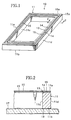
- Fig. 1 shows a mask protective device 10 according to the first embodiment of the present invention.
- the mask protective device 10 is provided with a rectangular frame 11, the size of which is set to surround a mask pattern (not shown).
- the frame 11 is generally called as "pellicle frame".
- the frame 11 has facing portions 11a, 11b on open end sides in an opposed relation, respectively. Two openings formed in the frame 11 extend in the same levels of the facing portions 11a, 11b, respectively.
- the facing portions 11a, 11b will be referred to as "end faces” for convenience.
- the frame 11 comprises an inner face 11c and outer face 11d.
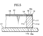
- the periphery of a transparent thin film 12 is bonded on one end face 11a of the frame 11 by adhesives 13 applied on the end face 11a in such a manner as to cover the opening as shown in Fig. 2.
- the transparent thin film 12 is generally called as "pellicle film".
- the adhesives 13 are linearly applied on the end face 11a of the frame 11 from the vicinity of one corner thereof along the end face 11a. After coming full circle on the frame, the adhesives 13 are further applied in parallel with the linear adhesives already applied to keep equal spaces therefrom. After coming another full circle, the application of the adhesives 13 is finished at the corner i.e. the starting point. Accordingly, the linear of the adhesives 13 is helically formed in two circles on the end face 11a of the frame 11.
- the adhesives 13 applied linearly in this manner swell to form string-like bead 14 protuberant from the end face 11a of the frame 11 as shown in Fig. 3.
- the groove 15 is curved along the end face 11a of the frame 11 and has one opening 15a communicating with the inside of the frame 11 and the other opening 15b communicating with the outside of the frame 11.
- the periphery of the transparent thin film 12 is put on and bonded to the helical string-like bead 14 which is made of the adhesives 13 linearly applied on the end face 11a of the frame 11.
- the groove 15 becomes an air passage 16 allowing the communication between the inside and the outside of the frame 11.
- the mask protective device 10 is disposed on the surface of the mask 17 as shown in Fig. 2 and is fixed to the surface of the mask 17 by pressure-sensitive adhesives 18a applied all around the end face 11b at the other opening of the frame 11. Therefore, since the inner space 19 of the mask protective device 10 communicates with the outside through the air passage 16 so that air in the mask protective device 10 moves in and out through the air passage 16, the thin film 12 neither swells nor dents even with changes in atmospheric pressure and/or in temperature and the optical characteristics of the film is thus never affected.
- pressure-sensitive adhesives 18b are previously applied thinly to the whole surface of the end face 11a of the frame 11 to form a pressure-sensitive adhesive layer on the bottom face of the curved groove 15. It is preferable because the pressure-sensitive adhesive layer improves the efficiency of trapping foreign matter intending to enter into the mask protective device 10 through the air passage 16.
- the pressure-sensitive adhesives 18b are applied to the whole surface of the end face 11a in the example shown in Fig. 4, it is enough to apply the pressure-sensitive adhesives to only such a range as to form the pressure-sensitive adhesive layer on the bottom face of the groove 15.
- pressure-sensitive adhesives 18c are previously applied thinly to an inner surface of the periphery of the transparent thin film 12 to be put on the string-like bead 14 and the periphery with the pressure-sensitive adhesives 18c is put on and bonded to the string-like bead 14 so as to form a pressure-sensitive adhesive layer on the top inner face of the air passage 16, thereby improving the efficiency of trapping foreign matter intending to enter into the mask protective device 10 through the air passage 16.
- the air passage 16 of which side walls are the string-like bead 14 formed on the end face 11a of the frame 11 may have pressure-sensitive adhesive layers on both the bottom face and the top inner face thereof. Accordingly, further improvement in the trapping efficiency can be expected.
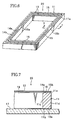
- Fig. 6 and Fig. 7 show a mask protective device 20 according to the second embodiment of the present invention.
- the mask protective device 20 according to the second embodiment comprises inner and outer string-like beads 14a, 14b spaced from each other extending all around the end face 11a at one opening of the frame 11. Therefore, a groove 15 formed between the inner and outer string-like beads 14a, 14b extends in the longitudinal direction and is curved on the end face 11a of the frame 11.
- the string-like beads 14a, 14b are formed by linearly applying adhesives 13 and the periphery of a transparent thin film 12 is put on and bonded to the string-like beads 14a, 14b.
- Neither the inner string-like bead 14a nor the outer string-like bead 14b is formed in a complete circle and both are each formed in a circle having at least one break. That is, the string-like beads 14a, 14b are each formed in a discontinuous circle, i.e. a line.
- the discontinuities i.e. breaks 15a, 15b are formed in different places on the end face 11a of the frame 11 so that the discontinuities 15a, 15b form openings of the curved groove 15 for communicating with the inside and the outside of the frame 11.
- the transparent thin film 12 is disposed in such a manner as to close one opening of the frame 11 and the periphery of the thin film 12 is put on and bonded to the inner and outer discontinuous string-like beads 14a, 14b formed by applying the adhesives 13 on the end face 11a of the frame 11.
- the groove 15 becomes an air passage 16 allowing the communication between the inside and the outside of the frame 11.
- the mask protective device 20 is disposed on the surface of the mask 17 as shown in Fig. 7 and is fixed to the surface of the mask 17 by pressure-sensitive adhesives 18a applied all around the end face 11b at the other opening of the frame 11. Therefore, since the inner space 19 of the mask protective device 20 communicates with the outside through the air passage 16 so that air in the mask protective device 20 moves in and out through the air passage 16, the thin film 12 neither swells nor dents even with changes in atmospheric pressure and/or in temperature and the optical characteristics of the film is thus never affected.
- pressure-sensitive adhesives 18b are previously applied thinly to the whole surface of the end face 11a of the frame 11 to form a pressure-sensitive adhesive layer on the bottom face of the curved groove 15. It is preferable because the pressure-sensitive adhesive layer improves the efficiency of trapping foreign matter intending to enter into the mask protective device 20 through the air passage 16. It should be understood that it is also enough to apply the pressure-sensitive adhesives to only such a range as to form the pressure-sensitive adhesive layer on the bottom face of the air passage 16.
- pressure-sensitive adhesives 18c are previously applied thinly to an inner peripheral surface of the transparent thin film 12 to be put on the string-like beads 14a, 14b and the periphery with the pressure-sensitive adhesives 18c thereof is put on and bonded to the string-like beads 14a, 14b so as to form a pressure-sensitive adhesive layer on the top inner face of the air passage 16, thereby improving the efficiency of trapping foreign matter intending to enter into the mask protective device 20 through the air passage 16.
- the air passage 16 of which side walls are the string-like beads formed on the end face 11a of the frame 11 may have pressure-sensitive adhesive layers on both the bottom face and the top inner face thereof. Accordingly, further improvement in the trapping efficiency can be expected.
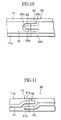
- Fig. 10 shows a part of a frame 11 in a mask protective device 30 according to the third embodiment of the present invention.
- the mask protective device 30 of this embodiment comprises a relatively wide string-like bead 31 formed in a single line in the width direction all around the end face 11a of the frame 11 by applying adhesives 13.
- the string-like bead 31 has at least one discontinuity.
- the discontinuity 32 is formed as follows.
- a recess 32a is formed to dent just like a bay in one end of the string-like bead 31 along the center line thereof and a tail portion 32b is formed to project just like a peninsula on the other end facing the one end in such a manner that the width of the recess 32a is greater than that of the tail portion 32b.
- the tail portion 32b on the other end of the string-like bead 31 is entered into the recess 32a without any contact between the outer surface of the tail portion 32b and the inner surface of the recess 32a as shown in Fig. 10.
- the periphery of the transparent thin film 12 is put on and bonded to the wide string-like bead 31 which is made of the adhesives 13 linearly applied on the end face 11a of the frame 11.
- the groove 33 becomes an air passage allowing the communication between the inside and the outside of the frame 11 through the both ends 33a, 33b.
- the mask protective device 30 is also disposed on the surface of the mask 17 and is fixed to the surface of the mask 17 by pressure-sensitive adhesives applied all around the end face 11b at the other opening of the frame 11. Therefore, since the inner space of the mask protective device 30 communicates with the outside through the air passage so that air in the mask protective device 30 moves in and out through the air passage, the thin film 12 neither swells nor dents even with changes in atmospheric pressure and/or in temperature and the optical characteristics of the film is thus never affected.
- the discontinuity 32 with the curved groove 33 crossing the wide string-like bead 31 in the direction of connecting the inside and the outside of the frame 11 may be designed in a large variety of configurations.
- the end portions 31a, 31b of the string-like bead 31 are shifted from the main track and arranged in parallel with each other in predetermined length so as to form a groove 33 as shown in Fig. 11.
- the end portions 31a, 31b of the string-like bead 31 may be each formed in a hook-like configuration so that the end portions 31a, 31b seem to be engaged with each other so as to form a groove 33 as shown in Fig. 12.
- pressure-sensitive adhesives are previously applied thinly to the whole surface of the end face 11a of the frame 11 to form a pressure-sensitive adhesive layer at least on the bottom face of the curved groove 33. It is preferable because the pressure-sensitive adhesive layer improves the efficiency of trapping foreign matter intending to enter into the mask protective device 30 through the air passage 16. It should be understood that the pressure-sensitive adhesives are not necessarily applied all around the end face 11a and it is enough to apply the pressure-sensitive adhesives to only a range where the discontinuity 32 of the string-like bead 31 extend.
- pressure-sensitive adhesives may be previously applied thinly to an inner peripheral surface of the transparent thin film 12 to be put on the string-like bead 31 and the periphery thereof is put on and bonded to the string-like bead 31 so as to form a pressure-sensitive adhesive layer on the top inner face of the air passage, thereby improving the efficiency of trapping foreign matter intending to enter into the mask protective device 30 through the air passage.
- the air passage of which side walls are portions of the string-like bead 31 formed on the end face 11a of the frame 11 may have pressure-sensitive adhesive layers on both the bottom face and the top inner face thereof. Accordingly, further improvement in the trapping efficiency can be expected.
- Fig. 13 partially shows a mask protective device 40 according to the fourth embodiment of the present invention.
- the periphery of a transparent thin film 12 is bonded to an end face 11a at one opening of a frame 11 by adhesives 41 applied on the whole surface of the end face 11a in such a manner that the transparent thin film 12 closes the opening of the frame 11.
- the string-like bead 42 formed on the end face 11b at the other opening of the frame 11 may be formed in a helical shape just like the first embodiment shown in Fig. 1.
- the string-like bead 42 may also be formed in two lines arranged inside and outside in parallel with each other in such a manner as to have respective discontinuities in different places so that the discontinuities become openings of a groove for communicating with the inside and the outside of the frame 11 just like the second embodiment as shown in Fig. 6.
- one string-like bead 42 is formed in a single line in the width direction all around the end face 11b of the frame 11 by applying adhesives in such a manner as to have at least one discontinuity.
- a curved groove can be formed at the discontinuity to cross the wide string-like bead 42 in the direction of connecting the inside and the outside of the frame 11.
- the mask protective device 40 is mounted on the surface of the mask 17 as shown in Fig. 13 and bonded to the mask 17 by the string-like bead 42 formed by applying the adhesives 13 on the end face 11b of the frame 11.
- the groove becomes an air passage 43 allowing the communication between the inside and the outside of the frame 11. Therefore, since the inner space 19 of the mask protective device 40 communicates with the outside through the air passage 43 so that air in the mask protective device 40 moves in and out through the air passage 43, the thin film 12 neither swells nor dents even with changes in atmospheric pressure and/or in temperature and the optical characteristics of the film is thus never affected.
- pressure-sensitive adhesives 18 are previously applied thinly to the end face 11b of the frame 11 to form a pressure-sensitive adhesive layer at least on the bottom face of the curved groove 43. It is preferable because the pressure-sensitive adhesive layer improves the efficiency of trapping foreign matter intending to enter into the mask protective device 40 through the air passage 43.
- the mask protective device 40 according to the fourth embodiment or the alternative of the present invention as shown in Fig. 13 and Fig. 14 is a best mode for carrying out this invention in actual practice.
- the reasons are as follows. Dusts adhering on the pellicle film 12 are normally removed by blowing, whereby the pellicle film 12 oscillates. There is a possibility that the pellicle film 12 comes off the frame 11 if the bonding strength between the pellicle film 12 and the pellicle frame (frame 11).
- the string-like bead is formed on a portion of the frame 11 to be in contact with the reticle i.e. mask 17 so that the pellicle film 12 can securely bonded to the end face of the frame 11 by the adhesives 41. Therefore, even when dusts adhering on the pellicle film 12 are removed by blowing, the pellicle film 12 never comes off the frame 11.
- Fig. 15 partially shows a mask protective device 50 according to the fifth embodiment of the present invention.
- the mask protective device 50 of this embodiment is a combination of the first embodiment and the fourth embodiment.
- a first string-like bead 51 is formed on the end face 11a at one opening of the frame 11 by applying adhesives all around the end face 11a.
- a transparent thin film 12 is disposed to close the one opening of the frame 11 and the periphery of the thin film 12 is bonded to the first string-like bead 51 applied on the end face 11a of the frame 11 in such a manner that the thin film 12 is spread.
- a curved groove formed between lines of the first string-like bead 51 becomes a air passage 52 allowing the communication between the inside and the outside of the frame 11 because the top of the curved groove is closed by the thin film.
- adhesives for bonding the frame 11 to the mask are also applied all around the end face 11b at the other opening of the frame 11, thereby forming a second string-like bead 53 by the adhesives.
- the mask protective device 50 is mounted on the surface of the mask 17 as shown in Fig. 9 and bonded to the mask 17 by the second string-like bead 53 formed by linearly applying the adhesives on the end face 11b of the frame 11.
- the groove becomes an air passage 54 allowing the communication between the inside and the outside of the frame 11. Therefore, since the inner space 19 of the mask protective device 50 communicates with the outside through the air passages 52, 54 so that air in the mask protective device 50 moves in and out through the air passages 52 54, the thin film 12 neither swells nor dents even with changes in atmospheric pressure and/or in temperature and the optical characteristics of the film is thus never affected.
- the string-like beads 51, 53 formed on the end faces 11a, 11b at both the openings of the frame 11 may be formed in helical shape just like the first embodiment shown in Fig. 1.
- the string-like beads 51, 53 may also be formed in two lines arranged inside and outside in parallel with each other in such a manner as to have respective discontinuities in different places so that the discontinuities become openings of a groove for communicating with the inside and the outside of the frame 11 just like the second embodiment as shown in Fig. 6.
- string-like beads 51, 53 may be each formed in a single line in the width direction all around the end face 11a, 11b of the frame 11 by applying adhesives in such a manner as to each have at least one discontinuity. Curved grooves can be formed at the discontinuities to cross the wide string-like beads 51, 53, respectively, in the direction of connecting the inside and the outside of the frame 11.
- pressure-sensitive adhesives are previously applied thinly to the end face 11a of the frame 11 to form a pressure-sensitive adhesive layer at least on the bottom face of the air passage 52. It is preferable because the pressure-sensitive adhesive layer improves the efficiency of trapping foreign matter intending to enter into the mask protective device 50 through the air passage 52.
- pressure-sensitive adhesives are previously applied thinly to an inner peripheral surface of the transparent thin film 12 to be put on the string-like bead 51 and the periphery thereof is put on and bonded to the string-like bead 51 so as to form a pressure-sensitive adhesive layer on the top inner face of the air passage 52, thereby improving the efficiency of trapping foreign matter intending to enter into the mask protective device 50 through the air passage 52.
- pressure-sensitive adhesives are previously applied thinly to the end face 11b of the frame 11 to form a pressure-sensitive adhesive layer at least on the bottom face of the air passage 54. It is preferable because the pressure-sensitive adhesive layer improves the efficiency of trapping foreign matter intending to enter into the mask protective device 50 through the air passage 54.
- the air passages of which side walls are the string-like beads 51, 53 formed on the end faces 11a, 11b of the frame 11 may have pressure-sensitive adhesive layers on both the bottom faces and the top inner faces thereof. Accordingly, further improvement in the trapping efficiency can be expected.
- the possible methods of forming such string-like beads as mentioned above on an end face of the frame in the mask protective device include a method in which relatively thick adhesives are placed on the frame by using the printing technology, a method in which adhesives are pushed out from a nozzle and linearly placed just like drawing, and a method in which after applying adhesives on the whole surface of the end face of the frame in a predetermined thickness, useless portions of the adhesives are removed by cutting or the like.
- epoxy acrylate, urethane acrylate, polyester acrylate, and polyethylene acrylate may be employed as adhesives for forming such a string-like bead.
- polystyrene and materials of which base polymer may be copolymer, polyisobutylene, polyester resin, vinyl acetate resin, ethylene-vinyl acetate copolymer, and polyethylene phenoxy resin may be employed as pressure-sensitive adhesives for forming the pressure-sensitive adhesive layer on the bottom of the curved groove and for fixing the frame to the mask.
- pressure-sensitive adhesive refers to material capable of bonding only with slight pressure without the aid of heat or catalyst.
- adhesive refers to material (Monomer and Pre-polymer type adhesive) which hardens by chemical reaction such as polymerization, condensation, and the like, material (solution and emulsion type adhesive) which hardens by vaporization of solvent or dispersion medium, and material (hot-melt adhesive) which hardens by cooling. The hardening of these materials results from forces of drawing mutually between molecules of adhesive and molecules of adherent.
- the string-like bead is formed by adhesives in the aforementioned embodiments, the same effect can be obtained with pressure-sensitive adhesives instead of the adhesives.
- the pressure-sensitive adhesives are applied on the end face of the frame or the periphery of the transparent thin film in order to form the pressure-sensitive adhesive layer on the bottom face or the top inner face of the air passage in the above embodiments, adhesives may be employed instead of the pressure-sensitive adhesives.
- the mask protective device of the present invention when adhesives or pressure-sensitive adhesives for fixing a transparent thin film to one or both of end faces of a frame, the size of which is set to surround a mask pattern, or fixing the frame to a mask surface are applied to form a string-like bead on the end face of the frame, a curved groove of which side walls are portions of the string-like bead is formed in such a manner as to allow the communication between the inside and the outside of the frame.
- the top of the curved groove is closed so that the curved groove becomes an air passage.
- the inside of the mask protective device is prevented from being hermetically sealed when it is mounted on the mask, thereby preventing the expansion and contraction of air in the mask protective device due to changes in atmospheric pressure and/or in temperature. Therefore, the thin film spread on the frame is prevented from swelling or denting due to changes in atmospheric pressure and/or in temperature with the result that the thin film is not damaged and the optical characteristics of the film can be kept well in conformity to the designed level.
- the present invention is effective as a cover for guarding a mask or reticle, which is used for photolithography in manufacturing processes of an integrated circuit, from dust and other particles.
Landscapes
- Physics & Mathematics (AREA)
- General Physics & Mathematics (AREA)
- Health & Medical Sciences (AREA)
- Engineering & Computer Science (AREA)
- Environmental & Geological Engineering (AREA)
- Epidemiology (AREA)
- Public Health (AREA)
- Preparing Plates And Mask In Photomechanical Process (AREA)
- Exposure And Positioning Against Photoresist Photosensitive Materials (AREA)
- Adhesive Tapes (AREA)
- Details Or Accessories Of Spraying Plant Or Apparatus (AREA)
Applications Claiming Priority (4)
| Application Number | Priority Date | Filing Date | Title |
|---|---|---|---|
| JP18714596 | 1996-07-17 | ||
| JP18714596 | 1996-07-17 | ||
| JP187145/96 | 1996-07-17 | ||
| PCT/JP1997/002368 WO1998002783A1 (fr) | 1996-07-17 | 1997-07-08 | Dispositif de protection de masque |
Publications (3)
| Publication Number | Publication Date |
|---|---|
| EP0851294A1 true EP0851294A1 (fr) | 1998-07-01 |
| EP0851294A4 EP0851294A4 (fr) | 2000-04-05 |
| EP0851294B1 EP0851294B1 (fr) | 2004-02-25 |
Family
ID=16200918
Family Applications (1)
| Application Number | Title | Priority Date | Filing Date |
|---|---|---|---|
| EP97929565A Expired - Lifetime EP0851294B1 (fr) | 1996-07-17 | 1997-07-08 | Dispositif de protection de masque |
Country Status (9)
| Country | Link |
|---|---|
| US (1) | US6083577A (fr) |
| EP (1) | EP0851294B1 (fr) |
| JP (1) | JP3606880B2 (fr) |
| KR (1) | KR19990045743A (fr) |
| CA (1) | CA2231175A1 (fr) |
| DE (1) | DE69727782T2 (fr) |
| MY (1) | MY120124A (fr) |
| TW (1) | TW369621B (fr) |
| WO (1) | WO1998002783A1 (fr) |
Families Citing this family (13)
| Publication number | Priority date | Publication date | Assignee | Title |
|---|---|---|---|---|
| JP2002182373A (ja) * | 2000-12-18 | 2002-06-26 | Shin Etsu Chem Co Ltd | ペリクル及びその製造方法及びフォトマスク |
| US7008487B1 (en) | 2002-03-04 | 2006-03-07 | Micron Technology, Inc. | Method and system for removal of contaminates from phaseshift photomasks |
| DE10246788B4 (de) * | 2002-10-08 | 2007-08-30 | Infineon Technologies Ag | Schutzvorrichtung für Reflexionsmasken und Verfahren zur Verwendung einer geschützten Reflexionsmaske |
| US7094505B2 (en) * | 2002-10-29 | 2006-08-22 | Toppan Photomasks, Inc. | Photomask assembly and method for protecting the same from contaminants generated during a lithography process |
| US7316869B2 (en) * | 2003-08-26 | 2008-01-08 | Intel Corporation | Mounting a pellicle to a frame |
| US7264853B2 (en) * | 2003-08-26 | 2007-09-04 | Intel Corporation | Attaching a pellicle frame to a reticle |
| US20050202252A1 (en) * | 2004-03-12 | 2005-09-15 | Alexander Tregub | Use of alternative polymer materials for "soft" polymer pellicles |
| US7314667B2 (en) * | 2004-03-12 | 2008-01-01 | Intel Corporation | Process to optimize properties of polymer pellicles and resist for lithography applications |
| US8087296B2 (en) | 2006-03-15 | 2012-01-03 | Panasonic Corporation | Angular velocity sensor |
| JP2016139103A (ja) * | 2015-01-29 | 2016-08-04 | 日本軽金属株式会社 | ペリクル用支持枠 |
| TWI669565B (zh) * | 2018-09-26 | 2019-08-21 | 美商微相科技股份有限公司 | Photomask protection component structure |
| CN109814333A (zh) * | 2019-01-25 | 2019-05-28 | 上海微择科技有限公司 | 一种高性能的防污染颗粒的光罩膜 |
| TWI687760B (zh) * | 2019-04-16 | 2020-03-11 | 家登精密工業股份有限公司 | 具有擾流結構的光罩盒 |
Family Cites Families (7)
| Publication number | Priority date | Publication date | Assignee | Title |
|---|---|---|---|---|
| FR2439418A1 (fr) * | 1978-10-17 | 1980-05-16 | Censor Patent Versuch | Masque pour projeter une image sur un substrat semi-conducteur |
| JPH0123137Y2 (fr) * | 1985-04-05 | 1989-07-17 | ||
| JPH0772793B2 (ja) * | 1986-09-05 | 1995-08-02 | 三井石油化学工業株式会社 | ペリクル |
| JPH02250055A (ja) * | 1988-12-09 | 1990-10-05 | Seiko Epson Corp | フォトマスク及び半導体装置の製造方法 |
| JPH02302757A (ja) * | 1989-05-17 | 1990-12-14 | Fujitsu Ltd | 冷却機能付ペリクル |
| JP2992585B2 (ja) * | 1991-05-17 | 1999-12-20 | デュポン・フォトマスクス・イン・コーポレイテッド | 圧力解放性ペリクル |
| US5529819A (en) * | 1995-04-17 | 1996-06-25 | Inko Industrial Corporation | Pellicle assembly with vent structure |
-
1997
- 1997-07-08 DE DE69727782T patent/DE69727782T2/de not_active Expired - Fee Related
- 1997-07-08 JP JP50583298A patent/JP3606880B2/ja not_active Expired - Fee Related
- 1997-07-08 KR KR1019980701985A patent/KR19990045743A/ko not_active Ceased
- 1997-07-08 EP EP97929565A patent/EP0851294B1/fr not_active Expired - Lifetime
- 1997-07-08 US US09/043,272 patent/US6083577A/en not_active Expired - Fee Related
- 1997-07-08 WO PCT/JP1997/002368 patent/WO1998002783A1/fr not_active Ceased
- 1997-07-08 CA CA002231175A patent/CA2231175A1/fr not_active Abandoned
- 1997-07-16 TW TW086110064A patent/TW369621B/zh active
- 1997-07-16 MY MYPI97003240A patent/MY120124A/en unknown
Also Published As
| Publication number | Publication date |
|---|---|
| CA2231175A1 (fr) | 1998-01-22 |
| KR19990045743A (ko) | 1999-06-25 |
| EP0851294A4 (fr) | 2000-04-05 |
| JP3606880B2 (ja) | 2005-01-05 |
| WO1998002783A1 (fr) | 1998-01-22 |
| DE69727782D1 (de) | 2004-04-01 |
| US6083577A (en) | 2000-07-04 |
| TW369621B (en) | 1999-09-11 |
| DE69727782T2 (de) | 2004-12-09 |
| MY120124A (en) | 2005-09-30 |
| EP0851294B1 (fr) | 2004-02-25 |
Similar Documents
| Publication | Publication Date | Title |
|---|---|---|
| US6083577A (en) | Mask protective device | |
| EP0752621B1 (fr) | Pellicule supportée par un châssis pour la protection d'un photomasque | |
| KR960003908B1 (ko) | 압력 완화 박막 | |
| KR0164946B1 (ko) | 마스크 보호장치 | |
| JP3267403B2 (ja) | フルオロポリマー膜の製造方法 | |
| JPWO1998002783A1 (ja) | マスク保護装置 | |
| US5213949A (en) | Method for selectively curing a liquid photosensitive resin by masking exposure | |
| US5085899A (en) | Dust-proof film | |
| US5529819A (en) | Pellicle assembly with vent structure | |
| JP2005509185A (ja) | 取り外し可能な光学ペリクル | |
| JPH04199055A (ja) | ペリクル構造体 | |
| KR101166460B1 (ko) | 펠리클 프레임, 및 이 프레임을 사용한 포토리소그래피용 펠리클 | |
| EP0267600B1 (fr) | Méthode de réticulation sélective de résines photosensibles liquides par exposition sous masque | |
| US6303196B1 (en) | Pellicle | |
| JPS6339703Y2 (fr) | ||
| JPH05341502A (ja) | ペリクル枠 | |
| JPH10198021A (ja) | 気圧調整用孔保護フィルター付きペリクル | |
| JP2000019536A (ja) | 液晶表示装置の製造方法 | |
| US20100167498A1 (en) | Substrate level bonding method and substrate level package | |
| JPH0123137Y2 (fr) | ||
| US6094805A (en) | Method for manufacturing magnetic head | |
| JPS6315250A (ja) | フォトマスク上の粒状物質を減少させる方法およびその装置 | |
| JP2658297B2 (ja) | 防塵膜の取付け方法 | |
| JP2003107679A (ja) | マスク保護装置の収納ケース | |
| CN119677245A (zh) | 一种光学传感器及其封装方法 |
Legal Events
| Date | Code | Title | Description |
|---|---|---|---|
| PUAI | Public reference made under article 153(3) epc to a published international application that has entered the european phase |
Free format text: ORIGINAL CODE: 0009012 |
|
| 17P | Request for examination filed |
Effective date: 19980318 |
|
| AK | Designated contracting states |
Kind code of ref document: A1 Designated state(s): DE FR GB IT NL |
|
| A4 | Supplementary search report drawn up and despatched |
Effective date: 20000221 |
|
| AK | Designated contracting states |
Kind code of ref document: A4 Designated state(s): DE FR GB IT NL |
|
| 17Q | First examination report despatched |
Effective date: 20020730 |
|
| GRAP | Despatch of communication of intention to grant a patent |
Free format text: ORIGINAL CODE: EPIDOSNIGR1 |
|
| GRAS | Grant fee paid |
Free format text: ORIGINAL CODE: EPIDOSNIGR3 |
|
| GRAA | (expected) grant |
Free format text: ORIGINAL CODE: 0009210 |
|
| AK | Designated contracting states |
Kind code of ref document: B1 Designated state(s): DE FR GB IT NL |
|
| REG | Reference to a national code |
Ref country code: GB Ref legal event code: FG4D |
|
| REF | Corresponds to: |
Ref document number: 69727782 Country of ref document: DE Date of ref document: 20040401 Kind code of ref document: P |
|
| PGFP | Annual fee paid to national office [announced via postgrant information from national office to epo] |
Ref country code: NL Payment date: 20040704 Year of fee payment: 8 |
|
| PGFP | Annual fee paid to national office [announced via postgrant information from national office to epo] |
Ref country code: GB Payment date: 20040707 Year of fee payment: 8 |
|
| PGFP | Annual fee paid to national office [announced via postgrant information from national office to epo] |
Ref country code: FR Payment date: 20040708 Year of fee payment: 8 |
|
| PGFP | Annual fee paid to national office [announced via postgrant information from national office to epo] |
Ref country code: DE Payment date: 20040715 Year of fee payment: 8 |
|
| ET | Fr: translation filed | ||
| RAP2 | Party data changed (patent owner data changed or rights of a patent transferred) |
Owner name: MITSUI CHEMICALS, INC. |
|
| PLBE | No opposition filed within time limit |
Free format text: ORIGINAL CODE: 0009261 |
|
| STAA | Information on the status of an ep patent application or granted ep patent |
Free format text: STATUS: NO OPPOSITION FILED WITHIN TIME LIMIT |
|
| NLT2 | Nl: modifications (of names), taken from the european patent patent bulletin |
Owner name: MITSUI CHEMICALS, INC. |
|
| 26N | No opposition filed |
Effective date: 20041126 |
|
| PG25 | Lapsed in a contracting state [announced via postgrant information from national office to epo] |
Ref country code: IT Free format text: LAPSE BECAUSE OF NON-PAYMENT OF DUE FEES;WARNING: LAPSES OF ITALIAN PATENTS WITH EFFECTIVE DATE BEFORE 2007 MAY HAVE OCCURRED AT ANY TIME BEFORE 2007. THE CORRECT EFFECTIVE DATE MAY BE DIFFERENT FROM THE ONE RECORDED. Effective date: 20050708 Ref country code: GB Free format text: LAPSE BECAUSE OF NON-PAYMENT OF DUE FEES Effective date: 20050708 |
|
| PG25 | Lapsed in a contracting state [announced via postgrant information from national office to epo] |
Ref country code: NL Free format text: LAPSE BECAUSE OF NON-PAYMENT OF DUE FEES Effective date: 20060201 Ref country code: DE Free format text: LAPSE BECAUSE OF NON-PAYMENT OF DUE FEES Effective date: 20060201 |
|
| GBPC | Gb: european patent ceased through non-payment of renewal fee |
Effective date: 20050708 |
|
| PG25 | Lapsed in a contracting state [announced via postgrant information from national office to epo] |
Ref country code: FR Free format text: LAPSE BECAUSE OF NON-PAYMENT OF DUE FEES Effective date: 20060331 |
|
| NLV4 | Nl: lapsed or anulled due to non-payment of the annual fee |
Effective date: 20060201 |
|
| REG | Reference to a national code |
Ref country code: FR Ref legal event code: ST Effective date: 20060331 |