EP0851832B1 - Anlage zum bearbeiten von gefässen, transportvorrichtung zum transportieren von gefässen und paletten dafür - Google Patents
Anlage zum bearbeiten von gefässen, transportvorrichtung zum transportieren von gefässen und paletten dafür Download PDFInfo
- Publication number
- EP0851832B1 EP0851832B1 EP96929159A EP96929159A EP0851832B1 EP 0851832 B1 EP0851832 B1 EP 0851832B1 EP 96929159 A EP96929159 A EP 96929159A EP 96929159 A EP96929159 A EP 96929159A EP 0851832 B1 EP0851832 B1 EP 0851832B1
- Authority
- EP
- European Patent Office
- Prior art keywords
- pallet
- face
- pallets
- vessels
- magnetic
- Prior art date
- Legal status (The legal status is an assumption and is not a legal conclusion. Google has not performed a legal analysis and makes no representation as to the accuracy of the status listed.)
- Expired - Lifetime
Links
- 238000012545 processing Methods 0.000 title claims abstract description 56
- 230000005291 magnetic effect Effects 0.000 claims abstract description 52
- 238000004140 cleaning Methods 0.000 claims description 23
- 238000001035 drying Methods 0.000 claims description 23
- 238000003860 storage Methods 0.000 claims description 16
- 239000000463 material Substances 0.000 claims description 11
- 229910052782 aluminium Inorganic materials 0.000 claims description 10
- XAGFODPZIPBFFR-UHFFFAOYSA-N aluminium Chemical compound [Al] XAGFODPZIPBFFR-UHFFFAOYSA-N 0.000 claims description 10
- 238000000576 coating method Methods 0.000 claims description 10
- 238000000034 method Methods 0.000 claims description 10
- 230000008569 process Effects 0.000 claims description 9
- 238000012546 transfer Methods 0.000 claims description 9
- 239000011248 coating agent Substances 0.000 claims description 8
- 125000006850 spacer group Chemical group 0.000 claims description 7
- 239000007788 liquid Substances 0.000 claims description 5
- 239000004411 aluminium Substances 0.000 claims description 4
- 239000000696 magnetic material Substances 0.000 claims description 4
- 238000005406 washing Methods 0.000 claims description 4
- 230000004888 barrier function Effects 0.000 claims description 3
- 238000003801 milling Methods 0.000 claims description 3
- 238000005238 degreasing Methods 0.000 claims description 2
- 230000000717 retained effect Effects 0.000 claims description 2
- 238000005304 joining Methods 0.000 claims 13
- 238000009434 installation Methods 0.000 claims 8
- 238000006073 displacement reaction Methods 0.000 claims 1
- 238000001125 extrusion Methods 0.000 claims 1
- 238000011144 upstream manufacturing Methods 0.000 claims 1
- 238000004519 manufacturing process Methods 0.000 abstract description 13
- 239000000443 aerosol Substances 0.000 abstract description 3
- 238000009825 accumulation Methods 0.000 abstract 1
- 239000003973 paint Substances 0.000 description 18
- 238000003754 machining Methods 0.000 description 6
- 238000010422 painting Methods 0.000 description 6
- 238000007639 printing Methods 0.000 description 5
- 230000008901 benefit Effects 0.000 description 4
- 239000004922 lacquer Substances 0.000 description 4
- 230000002093 peripheral effect Effects 0.000 description 4
- 239000007921 spray Substances 0.000 description 4
- 230000005294 ferromagnetic effect Effects 0.000 description 3
- 239000007789 gas Substances 0.000 description 3
- 238000007493 shaping process Methods 0.000 description 3
- 238000005507 spraying Methods 0.000 description 3
- 238000012549 training Methods 0.000 description 3
- 239000011324 bead Substances 0.000 description 2
- 238000010586 diagram Methods 0.000 description 2
- 239000012535 impurity Substances 0.000 description 2
- 238000012423 maintenance Methods 0.000 description 2
- 229910052751 metal Inorganic materials 0.000 description 2
- 239000002184 metal Substances 0.000 description 2
- 150000002739 metals Chemical class 0.000 description 2
- 230000000149 penetrating effect Effects 0.000 description 2
- 238000003825 pressing Methods 0.000 description 2
- 230000001360 synchronised effect Effects 0.000 description 2
- 229910000831 Steel Inorganic materials 0.000 description 1
- ATJFFYVFTNAWJD-UHFFFAOYSA-N Tin Chemical compound [Sn] ATJFFYVFTNAWJD-UHFFFAOYSA-N 0.000 description 1
- 230000015572 biosynthetic process Effects 0.000 description 1
- 230000001680 brushing effect Effects 0.000 description 1
- 239000003795 chemical substances by application Substances 0.000 description 1
- 210000000078 claw Anatomy 0.000 description 1
- 238000010276 construction Methods 0.000 description 1
- 230000007797 corrosion Effects 0.000 description 1
- 238000005260 corrosion Methods 0.000 description 1
- 238000005520 cutting process Methods 0.000 description 1
- 230000005347 demagnetization Effects 0.000 description 1
- 230000001419 dependent effect Effects 0.000 description 1
- 238000013461 design Methods 0.000 description 1
- 230000005489 elastic deformation Effects 0.000 description 1
- 239000012530 fluid Substances 0.000 description 1
- 238000010438 heat treatment Methods 0.000 description 1
- 230000001939 inductive effect Effects 0.000 description 1
- 238000003780 insertion Methods 0.000 description 1
- 230000037431 insertion Effects 0.000 description 1
- 230000007257 malfunction Effects 0.000 description 1
- 238000012986 modification Methods 0.000 description 1
- 230000004048 modification Effects 0.000 description 1
- 238000004806 packaging method and process Methods 0.000 description 1
- 239000002245 particle Substances 0.000 description 1
- 239000004033 plastic Substances 0.000 description 1
- 229920003023 plastic Polymers 0.000 description 1
- 230000001737 promoting effect Effects 0.000 description 1
- 239000011253 protective coating Substances 0.000 description 1
- 230000005855 radiation Effects 0.000 description 1
- 239000010959 steel Substances 0.000 description 1
- 210000002105 tongue Anatomy 0.000 description 1
- 239000002966 varnish Substances 0.000 description 1
- 238000009423 ventilation Methods 0.000 description 1
Images


Classifications
-
- F—MECHANICAL ENGINEERING; LIGHTING; HEATING; WEAPONS; BLASTING
- F27—FURNACES; KILNS; OVENS; RETORTS
- F27B—FURNACES, KILNS, OVENS OR RETORTS IN GENERAL; OPEN SINTERING OR LIKE APPARATUS
- F27B9/00—Furnaces through which the charge is moved mechanically, e.g. of tunnel type; Similar furnaces in which the charge moves by gravity
- F27B9/14—Furnaces through which the charge is moved mechanically, e.g. of tunnel type; Similar furnaces in which the charge moves by gravity characterised by the path of the charge during treatment; characterised by the means by which the charge is moved during treatment
- F27B9/20—Furnaces through which the charge is moved mechanically, e.g. of tunnel type; Similar furnaces in which the charge moves by gravity characterised by the path of the charge during treatment; characterised by the means by which the charge is moved during treatment the charge moving in a substantially straight path
- F27B9/24—Furnaces through which the charge is moved mechanically, e.g. of tunnel type; Similar furnaces in which the charge moves by gravity characterised by the path of the charge during treatment; characterised by the means by which the charge is moved during treatment the charge moving in a substantially straight path being carried by a conveyor
- F27B9/243—Endless-strand conveyor
-
- B—PERFORMING OPERATIONS; TRANSPORTING
- B23—MACHINE TOOLS; METAL-WORKING NOT OTHERWISE PROVIDED FOR
- B23Q—DETAILS, COMPONENTS, OR ACCESSORIES FOR MACHINE TOOLS, e.g. ARRANGEMENTS FOR COPYING OR CONTROLLING; MACHINE TOOLS IN GENERAL CHARACTERISED BY THE CONSTRUCTION OF PARTICULAR DETAILS OR COMPONENTS; COMBINATIONS OR ASSOCIATIONS OF METAL-WORKING MACHINES, NOT DIRECTED TO A PARTICULAR RESULT
- B23Q7/00—Arrangements for handling work specially combined with or arranged in, or specially adapted for use in connection with, machine tools, e.g. for conveying, loading, positioning, discharging, sorting
- B23Q7/14—Arrangements for handling work specially combined with or arranged in, or specially adapted for use in connection with, machine tools, e.g. for conveying, loading, positioning, discharging, sorting co-ordinated in production lines
- B23Q7/1426—Arrangements for handling work specially combined with or arranged in, or specially adapted for use in connection with, machine tools, e.g. for conveying, loading, positioning, discharging, sorting co-ordinated in production lines with work holders not rigidly fixed to the transport devices
-
- B—PERFORMING OPERATIONS; TRANSPORTING
- B65—CONVEYING; PACKING; STORING; HANDLING THIN OR FILAMENTARY MATERIAL
- B65G—TRANSPORT OR STORAGE DEVICES, e.g. CONVEYORS FOR LOADING OR TIPPING, SHOP CONVEYOR SYSTEMS OR PNEUMATIC TUBE CONVEYORS
- B65G15/00—Conveyors having endless load-conveying surfaces, i.e. belts and like continuous members, to which tractive effort is transmitted by means other than endless driving elements of similar configuration
- B65G15/30—Belts or like endless load-carriers
- B65G15/58—Belts or like endless load-carriers with means for holding or retaining the loads in fixed position, e.g. magnetic
-
- B—PERFORMING OPERATIONS; TRANSPORTING
- B65—CONVEYING; PACKING; STORING; HANDLING THIN OR FILAMENTARY MATERIAL
- B65G—TRANSPORT OR STORAGE DEVICES, e.g. CONVEYORS FOR LOADING OR TIPPING, SHOP CONVEYOR SYSTEMS OR PNEUMATIC TUBE CONVEYORS
- B65G21/00—Supporting or protective framework or housings for endless load-carriers or traction elements of belt or chain conveyors
- B65G21/20—Means incorporated in, or attached to, framework or housings for guiding load-carriers, traction elements or loads supported on moving surfaces
- B65G21/2009—Magnetic retaining means
- B65G21/2018—Magnetic retaining means for retaining the load on the load-carrying surface
-
- F—MECHANICAL ENGINEERING; LIGHTING; HEATING; WEAPONS; BLASTING
- F27—FURNACES; KILNS; OVENS; RETORTS
- F27D—DETAILS OR ACCESSORIES OF FURNACES, KILNS, OVENS OR RETORTS, IN SO FAR AS THEY ARE OF KINDS OCCURRING IN MORE THAN ONE KIND OF FURNACE
- F27D3/00—Charging; Discharging; Manipulation of charge
-
- F—MECHANICAL ENGINEERING; LIGHTING; HEATING; WEAPONS; BLASTING
- F27—FURNACES; KILNS; OVENS; RETORTS
- F27D—DETAILS OR ACCESSORIES OF FURNACES, KILNS, OVENS OR RETORTS, IN SO FAR AS THEY ARE OF KINDS OCCURRING IN MORE THAN ONE KIND OF FURNACE
- F27D3/00—Charging; Discharging; Manipulation of charge
- F27D3/06—Charging or discharging machines on travelling carriages
-
- B—PERFORMING OPERATIONS; TRANSPORTING
- B65—CONVEYING; PACKING; STORING; HANDLING THIN OR FILAMENTARY MATERIAL
- B65G—TRANSPORT OR STORAGE DEVICES, e.g. CONVEYORS FOR LOADING OR TIPPING, SHOP CONVEYOR SYSTEMS OR PNEUMATIC TUBE CONVEYORS
- B65G2201/00—Indexing codes relating to handling devices, e.g. conveyors, characterised by the type of product or load being conveyed or handled
- B65G2201/02—Articles
-
- B—PERFORMING OPERATIONS; TRANSPORTING
- B65—CONVEYING; PACKING; STORING; HANDLING THIN OR FILAMENTARY MATERIAL
- B65G—TRANSPORT OR STORAGE DEVICES, e.g. CONVEYORS FOR LOADING OR TIPPING, SHOP CONVEYOR SYSTEMS OR PNEUMATIC TUBE CONVEYORS
- B65G2201/00—Indexing codes relating to handling devices, e.g. conveyors, characterised by the type of product or load being conveyed or handled
- B65G2201/02—Articles
- B65G2201/0235—Containers
- B65G2201/0261—Puck as article support
-
- F—MECHANICAL ENGINEERING; LIGHTING; HEATING; WEAPONS; BLASTING
- F27—FURNACES; KILNS; OVENS; RETORTS
- F27D—DETAILS OR ACCESSORIES OF FURNACES, KILNS, OVENS OR RETORTS, IN SO FAR AS THEY ARE OF KINDS OCCURRING IN MORE THAN ONE KIND OF FURNACE
- F27D3/00—Charging; Discharging; Manipulation of charge
- F27D2003/0001—Positioning the charge
- F27D2003/0002—Positioning the charge involving positioning devices, e.g. buffers, buffer zones
-
- F—MECHANICAL ENGINEERING; LIGHTING; HEATING; WEAPONS; BLASTING
- F27—FURNACES; KILNS; OVENS; RETORTS
- F27D—DETAILS OR ACCESSORIES OF FURNACES, KILNS, OVENS OR RETORTS, IN SO FAR AS THEY ARE OF KINDS OCCURRING IN MORE THAN ONE KIND OF FURNACE
- F27D3/00—Charging; Discharging; Manipulation of charge
- F27D2003/0034—Means for moving, conveying, transporting the charge in the furnace or in the charging facilities
- F27D2003/0039—Means for moving, conveying, transporting the charge in the furnace or in the charging facilities comprising magnetic means
- F27D2003/004—Magnetic lifters
-
- F—MECHANICAL ENGINEERING; LIGHTING; HEATING; WEAPONS; BLASTING
- F27—FURNACES; KILNS; OVENS; RETORTS
- F27D—DETAILS OR ACCESSORIES OF FURNACES, KILNS, OVENS OR RETORTS, IN SO FAR AS THEY ARE OF KINDS OCCURRING IN MORE THAN ONE KIND OF FURNACE
- F27D3/00—Charging; Discharging; Manipulation of charge
- F27D2003/0034—Means for moving, conveying, transporting the charge in the furnace or in the charging facilities
- F27D2003/0063—Means for moving, conveying, transporting the charge in the furnace or in the charging facilities comprising endless belts
-
- Y—GENERAL TAGGING OF NEW TECHNOLOGICAL DEVELOPMENTS; GENERAL TAGGING OF CROSS-SECTIONAL TECHNOLOGIES SPANNING OVER SEVERAL SECTIONS OF THE IPC; TECHNICAL SUBJECTS COVERED BY FORMER USPC CROSS-REFERENCE ART COLLECTIONS [XRACs] AND DIGESTS
- Y10—TECHNICAL SUBJECTS COVERED BY FORMER USPC
- Y10T—TECHNICAL SUBJECTS COVERED BY FORMER US CLASSIFICATION
- Y10T29/00—Metal working
- Y10T29/51—Plural diverse manufacturing apparatus including means for metal shaping or assembling
- Y10T29/5196—Multiple station with conveyor
Definitions
- the invention relates to systems according to the preamble of claim 1, on devices according to the preamble of claim 8 and on pallets according to the preamble of Claim 10.
- Fig. 1 shows schematically the basic structure of the known Equipment for the production of aluminum cans. Of the Manufacturing process begins with a pressing process Press 30. Immediately afterwards in a rough processing device 31 is cut and if necessary brushing the raw vessels or cans. Subsequently the cans are placed on the mandrels of a chain conveyor 32 and by a cleaning station 33 with washing and Drying device performed. After cleaning, the Cans in an inner lacquer device 34 coated with lacquer on the inside.
- each can must be removed from the chain conveyor mandrel removed, placed in a holder and then in a sleeve-like, rotatable holder are introduced.
- the interior paint is moved by a nozzle that can be moved into the interior of the can dispensed while the can is rotated approximately. After that must each can from the sleeve-like holder into an oven bowl inserted and in it to dry by a first Oven 35 are passed before they are back on a mandrel Chain conveyor 32 is placed.
- the holding shells, the sleeve-shaped holders and the furnace shells are the current can diameter adapted and need for the production of Cans with different diameters are exchanged, leading to long downtimes.
- a first chain store 36 is provided which the number of supporting mandrels is reduced or increased and the number of mandrels returning increases accordingly or reduced.
- a second chain store 37 is after the interior paint station 34, 35 and in front of an outside processing station 38 provided.
- the outside processing station 38 includes a primer 39, a pressure 40 and one Top coat device 41. In all three devices 39-41 the cans are put on a mandrel by the chain, coated, put back on the chain and through led a drying oven. Do this due to the necessary Can movements essentially have the same problems on how to paint the interior.
- a final shaping device 43 for example with aerosol cans for shaping the can neck, and a packaging device 44 is provided.
- a solution is known from FR-A-2 416 855 in which Tin cans after printing using a magnetic conveyor to be continued.
- this solution can Aluminum cans are not used and also exists for cans that are printed over the entire can jacket, the danger that in the area of the magnetic conveyor Face of the can of paint on the conveying surface reached.
- EP-A-600 130 is a cup-shaped article holder known, the article used in the area of its outer surface with two oppositely arranged Holds pressed parts and a magnet in the floor area includes.
- These article holders are on a belt conveyor with a magnetic means under the conveyor surface on this held.
- the disadvantages of this article holder exist in that the magnet is unwanted to ferromagnetic Can fix parts of the conveyor and in particular also attracts ferromagnetic particles as impurities and carries along.
- the impurities carried along can Editing the articles lead to malfunctions. Processing steps with high temperatures can become partial Demagnetization of the magnet and poor holding properties to lead.
- the cup shape makes it impossible and the pressed parts machining the outside of the Article jacket.
- EP-A-402 703 is a transport system for coils known in the protruding from a conveyor belt Magnets on ferromagnetic pallets at fixed intervals to carry along with the tape. This solution creates synchronization problems, that solved with complex plant parts Need to become.
- the object of the invention is now a system for processing vessels from any, in particular non magnetic material to describe the easier and is more flexible and with a smaller size Synchronization effort is connected.
- the device be designed for transportation so that Passing to processing stations is simplified.
- the conveying area can affect storage areas, for Compensating for fluctuations in throughput and transfer areas, to provide cans at transfer points be formed.
- the processing stations pick up according to their processing frequency cans to be processed from one Storage area or from a transfer point and lead this after processing on a conveyor surface without synchronization.
- the pallet at least in critical funding areas prevent the pad from being accidentally detached from the Conveyor surface loosens or the can tilts with the pallet the pallet at least partially made of magnetizable material trained and the conveying surface is in this area at least one permanent magnet or possibly one Electromagnet element assigned so that the pallet due of magnetic forces adheres to the conveying surface.
- the pallet includes a pallet connection surface for creating to a conveying surface and a connecting surface with at least a connecting device for connecting the pallet with a can surface, the pallet connection surface and the connection surface is substantially parallel are arranged.
- a preferred dose orientation relative to achieve the conveying surface is the can end surface connected to the connecting surface. This ensures that the can axis is always essentially vertical is aligned to the conveyor area.
- the pallet held on the bottom of the can is the can of freely accessible from the can opening and can be removed without having to put it down into a holding bowl directly on a holding mandrel for the external machining or in a sleeve for the internal machining be pushed.
- the use of magnetizable Pallet has the advantage of being actuated of the can movements with compressed air pulses if necessary can be dispensed with.
- the can not inserted into a sleeve for internal treatment, it is made by someone who holds the pallet magnetically, magnetic holding surface worn.
- the holding surface is particularly designed to be rotatable.
- the magnetic holding surfaces have opposite the sleeves the advantage that when changing to a different can diameter don't need to be replaced because they to hold different sized cans on the same size Pallets and preferably also for holding different large pallets can be formed.
- the cans are optionally with a magnetic Turntable and / or fixed or moving, with the pallets guides which come into contact with the guide moved in positions which the holding elements are opposite. If the movement of the Turntables synchronous and concentric with the movement of one Turning drum with holding elements takes place, the handover also take place on moving holding elements.
- the conveying device comprises guide elements which the the conveying surface of moving vessels, in particular through leading ones Touch contacts with pallets, along desired Make paths feasible, the guide elements if necessary are movable by an actuator. Thereby can be separated with simple means, for dividing the supplied vessels on at least two sub-lines, to be provided.
- the partial lines lead to parallel processing stations. After editing in the stations arranged in parallel a merging device merging the vessels of at least two sub-lines.
- Such parallel processing would be disproportionate for systems with chain conveyors complex.
- the furnaces are preferably fed by means of belt conveyors, the cans each in the oven for drying restrain in a traffic jam area.
- the cans By placing the cans on the Pallets can be picked up standing in the ovens drying is significantly simplified. Especially for the drying of the inner varnish makes the oven bowls superfluous and when changing the system to another can size, they no longer need to be replaced.
- drying the outer coating leads according to prior art chain through the furnace. By this chain dissipates more thermal energy from the furnace than through appropriately dimensioned pallets.
- the systems according to the invention are not only in construction flexible but also enable with minimal changeover effort, the processing of many different sizes and shaped cans or vessels.
- At least two common can types can use the same range can be used for different types of cans.
- the can height doesn't matter what compared to the bracket Thorns are another benefit.
- the pallets are in the beginning of the system with the Connected cans, separated from them in the end area and by means of a pallet return to the starting area guided.
- a Pallet cleaning and in particular a pallet warehouse are provided.
- the same system can easily be used with different Pallet types, for example pallet types with different Pallet cross-sections are operated.
- This will the pallet warehouse preferably designed so that it all Store each type of pallet in separate areas and / or promote to the plant start area if necessary can.
- the systems according to the invention are also not on Restricted cans from certain material. As can material come metals, both magnetizable and not magnetizable, and also not metals, in particular Plastics in question.
- the wide range of uses of the Plants or at least parts of plants result from the Conveyor device the magnetic conveyor together with magnetizable Pallets includes.
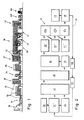
- FIG. 2 shows a flow diagram of a process according to the invention Plant for the production of aluminum cans.
- a press 30 is provided as the first processing station.
- the raw ones Cans consist of a cylindrical jacket on one At the end a filling opening and at the other end an end surface having. At least from the end surface one, essentially in the axial direction from the vessel to the outside leading, preferably centrally arranged, connecting part in front.
- the cans are then in a raw processing station 31 'cut to the desired length, optionally brushed and provided with a palette.
- the station 31 'thus comprises a palletizing device, the the connection surface of the box with the connection surface connects the pallet, preferably by the connecting part inserted into an opening of the pallet and in particular from a riveting device fixed to the pallet is connected.
- cans with pallets can be packed into one Storage 45 for small series are introduced.
- a magnetic belt conveyor which may also be loaded from the pre-storage is, through a cleaning station 33.
- the cans are by means of the pallets on the conveyor through various Cleaning areas such as degreasing and rinsing areas, the conveyor being arranged so that the cans before leaving any cleaning area with the vessel opening are kept down to the most complete possible To ensure leakage of cleaning fluid and when entering, at least before leaving if applicable, provided baths with the opening after are held up to complete filling of the To enable the inside of the can with cleaning liquid.
- the pallets are preferably with an actuatable restraint, in particular one Barrier to the the pallet directly to the restraint abut adjacent vessels, restrained.
- the conveying surface moves smoothly under the connection surfaces of the jammed pallets.
- the cans are ready when the subsequent interior lacquer device 34 by means of a preferably magnetic feed conveyor, especially one Turntable fed and from this approximately in a horizontal Alignment in rotatable, the cans when injecting the Paint rotating, mounts added.
- the cans can just as easily be planted in vertical alignment and be painted. On the turning during painting could then possibly be omitted become. Because the can opening with the promotion The cans do not necessarily have to be freely accessible on pallets inserted into a holder of the interior paint device but can be painted directly into the paint their pallets are placed on cans standing on a conveying surface, as shown in Fig. 5.
- the funding area can be moved or stopped during painting be.
- the at least one painting nozzle must be feedable to the cans be arranged.
- the funding according to the invention of cans on magnetizable pallets has the advantage that they have both processing stations with plants Conveyor chains as well as with the new funding concept Processing stations, can be used. This means, that the conveyor chain for an existing system removed and the promotion between the old processing stations through the funding according to the invention Pallets and magnetic conveyors can be replaced. It understands of itself that plants with processing stations that are designed for the new funding concept, still can be formed more advantageously.
- the cans preferably pass from the interior lacquer device 34 on a belt conveyor in an interior paint oven 35 ', in which they are used for drying in a storage area can be retained on the belt conveyor. About heat loss and the escape of any gases released can decrease, the furnace 35 'at the beginning of the filling the outlet side and at the end of the filling also on the Entry side to be closed. After drying the outlet side opened so that the cans from the Storage area in the furnace 35 'continued on the belt conveyor become. To release unwanted gases is reduced during the can entry in the oven 35 ' Aspirated gas and fed to a cleaning. The in the Oven 35 'incoming fresh air is preferably over the escaping cans resulted in them being preheated by these gets into the oven 35 '.
- a conveyor belt runs through these ovens, preferably has a standard width and a jam load with rows of cans corresponding to the range is loaded.
- the belt speed is chosen so that the maximum can flow continues through the furnace can be.
- To achieve the necessary heating time or drying, must be the length of the furnace of the belt speed be chosen accordingly. After the oven, they can be run in parallel current rows of cans, especially when exiting be separated again from a storage area.
- the cans for the interior painting are no longer on theirs Systems must also be kept outside expedient, where the outer coating before the inner coating he follows. With such systems, the cans no longer held from the inside after the interior painting be what the stress on the fresh interior paint layer reduced. To put on a holder of the cans from the inside the cans could essentially be dispensed with the external treatment, for example, on the pallet and only in a small inner area held at the can opening become.
- each of the three exterior coatings drying is carried out in a common oven arrangement 47 to perform.
- the cans preferably get into on a conveyor belt a first drying area 47a of the oven arrangement 47 and from there to a printing device 40 '.
- the cans pass through a second drying area 47b to a paint system 41 'and from this through a third drying area 47c to one Depalletizing device 48.
- the outer coatings preferably on the horizontally held cans, it may be to simplify the handover to and from those leading through the drying areas Appropriate conveyor, this at least in the transfer areas as a magnetic conveyor with essentially vertical To develop conveyor areas.
- the drying takes place continuously in tunnel ovens that are open on both sides, or in full discontinuous, as with the interior paint oven 35 ' described.
- the depalletizing device 48 comprises a release agent for separating the pallet from the can, in particular for Removing at least a portion of one from the can interface projecting connector connected to the pallet.
- a milling device is provided facing away from the can Milled off the rivet head on the side of the pallet. With a Stop device present on the pallet can be prevented that something is milled off the pallet. After milling, the two become a separator Allow parts to be continued.
- the cans without pallets are in a subsequent Finishing device 43 treated further, in particular by the can base is pressed into the desired shape and if necessary the connector is completely removed When opening the can, a neck is used to hold a valve educated.
- a neck is used to hold a valve educated.
- the bottom shaping pallets can be used that are adapted to the shape of the floor.
- the pallets arrive via a pallet return 49, preferably via an at least partially magnetic Belt conveyor, preferably from depalletizing station 48 via a pallet cleaning device 50 and / or a Pallet storage device 51 to the palletizing station 31 '.
- a pallet return 49 preferably via an at least partially magnetic Belt conveyor, preferably from depalletizing station 48 via a pallet cleaning device 50 and / or a Pallet storage device 51 to the palletizing station 31 '.
- a pallet return 49 preferably via an at least partially magnetic Belt conveyor, preferably from depalletizing station 48 via a pallet cleaning device 50 and / or a Pallet storage device 51 to the palletizing station 31 '.
- a pallet return 49 preferably via an at least partially magnetic Belt conveyor, preferably from depalletizing station 48 via a pallet cleaning device 50 and / or a Pallet storage device 51 to the palletizing station 31 '.
- the pallets currently being returned at least as many pallets as there are cans can be in progress.
- the pallet 107 has a pallet connection surface 122 for application to a conveying surface and a connecting surface 121 with at least one connecting device for connecting the pallet 107 to a can bottom surface 130 includes, the pallet pad 122 and the Connection surface 121 substantially parallel to each other are arranged.
- the Pallet connection surface 122 ring-shaped and the connection surface 121 disc-shaped.
- the two faces 121 and 122 are of a preferably cylindrical Distance holding surface 131 at the desired distance from one another held.
- the spacing surface 131 preferably leads from the inner edge of the pallet connection surface 122 to Outer edge of the connecting surface 121.
- the connecting device comprises at least one, preferably a central, connection opening 117 at the one Connection part 132 of the can surface 130, if necessary by friction, but preferably form-fitting; in particular can be fixed by a riveting process.
- a riveting process Through the riveting process the free end of the connector 132 on the the side of the connecting surface 121 remote from the can deformed beyond the edge of the opening.
- a spring tension constructed by the connection surface 121 and the Can surface 130 of spacer elements 133 in the area of the connecting part 132 is slightly spaced. It is preferred at least three symmetrically around the connection opening 117 ribs arranged.
- connection surface 122 On the outer edge of the pallet connection surface 122 there is an im substantially perpendicular to the connection surface 122, from the connection surface 122 against the connection surface 121 extending side contact surface 134 intended.
- the pallets come into contact with this contact surface 134 with guide elements or with each other in management or Spacer contact.
- the pallets are preferably so for receiving cans dimensioned that the can cross-sections or diameters between the cross sections or diameters of the Spacer 131 and the contact surface 134 are. This ensures that when printing, the printing roller can protrude beyond the bottom of the can and the Cans cannot touch each other.
- the Promoting cans without contact is particularly direct important after the external treatment because it creates a Damage to the still fresh coating prevented can be. All with three different sized pallets To be able to accommodate common cans, for example following can diameter ranges 22-35mm, 35-53mm and Dimensioned 53-66mm pallets.
- FIG. 4 shows a pallet constructed analogously to the pallet 107 107 'for tubes 103'.
- the threaded part 132 ' used as a connecting part.
- disconnecting tube and the bead must be removed from the pallet. So that none subsequent processing on the threaded part 132 'is necessary, is at least in a preferred embodiment of the pallet 107 ' a, in particular resilient, locking device is provided.
- a groove attached To simply snap this device into place To ensure the tube 103 'is about cutting of the thread on part 132 ', preferably on the tube side End of the threaded part 132 ', a groove attached.
- the least a locking device which in the pressed state can be guided over the thread, snaps in the holding state in the groove so that the tube is held on the pallet becomes.
- the pallet includes contact areas, preferably three, on which corresponding areas of the outer surface of the tube if the tube of the locking device is held on the pallet.
- the latching device preferably comprises three spring tongues.
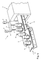
- FIG. 5 schematically shows an interior paint processing station with a spray apparatus 1 with spray nozzles 2 for application a protective coating against corrosion inside Boxes 3 made of a non-magnetic material, such as aluminum.
- a drying room 4 which e.g. as Tunnel furnace is formed. It can be training either be hit with the cans on the other, not shown end of the drying room, or they are in from the lower run of a belt conveyor 5 to be described again to the left (refer to Fig. 5) led out.
- a drying room 4 which e.g. as Tunnel furnace is formed.
- It can be training either be hit with the cans on the other, not shown end of the drying room, or they are in from the lower run of a belt conveyor 5 to be described again to the left (refer to Fig. 5) led out.
- the side of the lower run of the belt conveyor 5 processing devices arrange like one more Spraying device.
- the belt conveyor 5 is on well-known magnetic belt conveyor is formed by either 5 small permanent magnets are incorporated into the belt and run around with it or on the underside of the belt 5 stationary magnetic plates 6 are arranged, the latter if necessary cooperate with electromagnets arranged thereon or are also permanently magnetic.
- Second belt conveyor 8 can be provided, which in principle also as a magnetic belt conveyor is trained.
- oblique deflection surfaces located to the running direction (arrow 9) of the belt 8 10 provided, preferably not on the cans 3rd attack (to protect their outer surface), but to the sliding pallets 7.
- the cans 3 under the Invention easily in pairs (or even larger Number) on the respective belt 5 or 8, so as to increase productivity.
- the processing facilities are of course multiple each to be arranged side by side.
- the deflection surfaces can then also instead of just arrow-shaped with a single slope, formed with a tip located centrally on the belt 8 to the cans 3 left and right, respectively (referred to the direction of rotation 9).
- belts 5 and 8 as funding to provide; for example, a belt can also be a Turntable must be assigned laterally, on which the respective Can be moved one turn on the turntable, about to paint, to perform for this Process to give time without the respective belt conveyor to stop and operate intermittently, can the deflection surfaces 10 instead of stationary (as in Fig. 5 shown and for example on not shown
- the belt conveyor 8 attached to be arranged, also controlled, for example, each in the train the belt conveyor, e.g.
- baffles 10 are clocked according to the arrival of cans 3 at the respective location can be moved.
- an exact one Control can be used, of which an embodiment in Fig. 5 is shown.
- Spray liquid, such as paint, is supplied to the nozzles then via at least one connected to the carrier 13, not shown hose or one hose each for each nozzle 2.
- a sensor 14 is provided, which can be designed as such.
- the Transducer 16 for example, that reflected from the cans 3 Receives light.
- magnetizable pallets 7 means in generally the use of a relatively heavy material.
- Pallet 7 at least one penetrating their thickness and the has an opening connecting both main surfaces, which on the one hand reduces weight, on the other hand but may also serve additional purposes, as explained below becomes.
- FIG. 6 are next to one central opening 17 and further openings 18 are also provided.
- These openings 17, 18 can on the one hand as depressions for receiving projections of the cans, such as a lower can rim 19 (Fig. 8), i.e. as a holding device, serve, but of course is also an opposite order possible where the pallet fits into a recess the can 3 penetrating or surrounding its edge Has a head start.
- this latter variant will not be preferred because it is generally complete Machining the can surface is cheaper if it is freely accessible. This is also the reason for that Special training according to FIG. 8 discussed later and 5.
- FIG. 7 the cross-sectional shape can be designed according to FIG. 7 be where a pallet 7a is shown with a keyway 20 is.
- this keyway 20 for example two appropriately trained and approximately at an angle relative to the central axis A arranged on the circumference friction discs work together. Theoretically, one would also be Belt drive conceivable, but this belt would then have to be around Scope of the respective pallet 7a are placed. It understands but that for the rotary drive of the pallets themselves other forms of their peripheral surface, such as more or less smooth or serrated peripheral surfaces (for the intervention a gear) are possible.
- the central opening 17 also for pushing through a drive shaft be exploited, but this will generally not be practical. In the embodiment according to Fig. 7 should also be mentioned that the central opening 17 is such can be large that the pallet 7a (as well as the Pallets 7b and 7c) discussed later is annular.
- a deflection surface 10 (see FIG. 5) to engage it.
- These deflection surfaces should expediently have a thickness which corresponds at most to the thickness of the pallet 7a so there are definitely no scratch marks on the can surfaces leave.
- the deflection surfaces can even arranged at the height of the individual piece goods if it has less sensitive areas, as is the case with the cans 3 shown, in which case the pallets if necessary also with the respective sponsors could be firmly connected.
- Fig. 7 is the flat design of the pallet 7a visible, which is therefore one of the (assumed here above) Can facing connection or main surface 21 and one the magnetic conveyor (5 or 8) facing connection or Main surface 22 will have.
- the pallet 7c has a smaller one Scope as the box 3, as can be seen from Fig. 8.
- FIG. 9 Another solution for a pallet 7c is shown in FIG. 9.
- the stability of the (relatively light) can 3 on the To increase the range, its lower edge 19a can be an external thread have that in an internal thread 26 of the pallet 7c is screwed in.
- the accessibility of the peripheral surface of the In this exemplary embodiment, socket 3 is secured that the pallet 7c has a domed upper major surface 21a, but by a distance s over the circumference the can protrudes, which improves the stability.
- the curvature of the surface 21a can also be caused by corrugations (see the dashed concave section 27) with spacers be provided to improve air access.
- the openings 17, 18 for insertion serve and trained by machining facilities or be arranged.
- a magnetic belt conveyor is preferred are, as already mentioned, others with magnets cooperating sponsors conceivable. It could also be a palette for receiving several piece goods 3, for example a pair of cans 3; be trained, though this will generally not be preferred.
Landscapes
- Engineering & Computer Science (AREA)
- Mechanical Engineering (AREA)
- General Engineering & Computer Science (AREA)
- Specific Conveyance Elements (AREA)
- Coating Apparatus (AREA)
- Branching, Merging, And Special Transfer Between Conveyors (AREA)
- Cleaning In General (AREA)
- Stacking Of Articles And Auxiliary Devices (AREA)
- Attitude Control For Articles On Conveyors (AREA)
- Warehouses Or Storage Devices (AREA)
- Forklifts And Lifting Vehicles (AREA)
- Non-Mechanical Conveyors (AREA)
- Multi-Process Working Machines And Systems (AREA)
- Automatic Assembly (AREA)
Applications Claiming Priority (6)
| Application Number | Priority Date | Filing Date | Title |
|---|---|---|---|
| CH265795 | 1995-09-20 | ||
| CH2657/95 | 1995-09-20 | ||
| CH265795 | 1995-09-20 | ||
| DE29605595U | 1996-03-26 | ||
| DE29605595U DE29605595U1 (de) | 1995-09-20 | 1996-03-26 | Anlage zum Bearbeiten von Gefäßen, Transportvorrichtung zum Transportieren von Gefäßen und Paletten dafür |
| PCT/CH1996/000318 WO1997011015A1 (de) | 1995-09-20 | 1996-09-16 | Anlage zum bearbeiten von gefässen, transportvorrichtung zum transportieren von gefässen und paletten dafür |
Publications (2)
| Publication Number | Publication Date |
|---|---|
| EP0851832A1 EP0851832A1 (de) | 1998-07-08 |
| EP0851832B1 true EP0851832B1 (de) | 1999-08-18 |
Family
ID=25691074
Family Applications (1)
| Application Number | Title | Priority Date | Filing Date |
|---|---|---|---|
| EP96929159A Expired - Lifetime EP0851832B1 (de) | 1995-09-20 | 1996-09-16 | Anlage zum bearbeiten von gefässen, transportvorrichtung zum transportieren von gefässen und paletten dafür |
Country Status (12)
| Country | Link |
|---|---|
| US (1) | US6112389A (cs) |
| EP (1) | EP0851832B1 (cs) |
| JP (1) | JP4132073B2 (cs) |
| CN (1) | CN1113030C (cs) |
| AT (1) | ATE183479T1 (cs) |
| AU (1) | AU6868396A (cs) |
| BR (1) | BR9610561A (cs) |
| CA (1) | CA2231469C (cs) |
| CZ (1) | CZ297471B6 (cs) |
| DE (2) | DE29605595U1 (cs) |
| ES (1) | ES2137723T3 (cs) |
| WO (1) | WO1997011015A1 (cs) |
Families Citing this family (24)
| Publication number | Priority date | Publication date | Assignee | Title |
|---|---|---|---|---|
| JPH0687276U (ja) * | 1993-06-02 | 1994-12-22 | 秀憲 石井 | ティッシュペーパーケース |
| DE19739326C1 (de) * | 1997-09-09 | 1999-04-29 | Fehland Engineering Gmbh | Vorrichtung zur Behandlung von Getränkebehältern in einem Raum |
| DE19816232A1 (de) * | 1998-04-10 | 1999-10-14 | Schlafhorst & Co W | Transportsystem für Spinnspulen und Spulenhülsen mit einem einen Durchgang überbrückenden Transportweg |
| DE19859956A1 (de) | 1998-12-28 | 2000-06-29 | Alusuisse Lonza Services Ag | Anlage zum Bearbeiten von Behältern |
| DE19859955C2 (de) * | 1998-12-28 | 2002-06-13 | Alusuisse Tech & Man Ag | Palette für eine Fördervorrichtung insbesondere in einer Anlage zum Bearbeiten von Behältern |
| DE19920365A1 (de) * | 1999-05-04 | 2000-11-30 | Emil Stark | Verfahren und Vorrichtung zur Bearbeitung von Werkstücken mit lösbarem Werkstückträger |
| CH705057B1 (de) * | 2003-05-13 | 2012-12-14 | Soudronic Ag | Bearbeitungseinrichtung und Verwendung derselben zur Herstellung von Deckeln mit Aufreissfolie. |
| DE202011109945U1 (de) | 2011-11-25 | 2012-08-23 | GESI Gewindesicherungs-GmbH | Behandlungsanordnung für ferromagnetische Teile |
| CN102862703B (zh) * | 2012-10-23 | 2015-12-09 | 钟锦唐 | 水平给料式包装机 |
| CN104128853B (zh) * | 2013-05-02 | 2017-06-16 | 东莞精锐电器五金有限公司 | 工件卸料装置及可自动卸料的磨床 |
| CN103434750B (zh) * | 2013-08-20 | 2016-08-10 | 昆山一邦泰汽车零部件制造有限公司 | 变压器磁芯循环排列架 |
| CN103600961A (zh) * | 2013-10-29 | 2014-02-26 | 格林精密部件(苏州)有限公司 | 铁屑收集输送装置 |
| CN103723440A (zh) * | 2013-12-31 | 2014-04-16 | 吴江市松陵镇铭益自动化机械设备厂 | 一种金属件传送装置 |
| CN105135877B (zh) * | 2015-08-25 | 2017-07-18 | 大埔县特陶科技有限公司 | 循环输送设备及使用该设备的无烟无臭节能环保排蜡隧道窑 |
| EP3452377B1 (en) | 2016-05-04 | 2021-09-29 | Curium US LLC | Conveyance system for operation in radioactive environment |
| AT519095B1 (de) * | 2016-10-20 | 2018-04-15 | Trumpf Maschinen Austria Gmbh & Co Kg | Beschickungsverfahren für eine Werkzeugmaschine |
| CN107600894B (zh) * | 2017-09-05 | 2023-05-26 | 杭州中亚机械股份有限公司 | 一种连续输送用载具 |
| EP3476524A1 (de) * | 2017-10-27 | 2019-05-01 | Bystronic Laser AG | Werkstückauflage einer bearbeitungsmaschine für flächige werkstücke |
| CN109896256B (zh) * | 2019-04-13 | 2024-03-19 | 中山市四海智能装备有限公司 | 一种输送线兼容不同宽度托盘装置及其使用方法 |
| CN110451215B (zh) * | 2019-08-27 | 2024-08-13 | 桂林电子科技大学 | 一种容器自动装卸一体化装置 |
| CN110893562A (zh) * | 2019-12-23 | 2020-03-20 | 合肥众石机电科技有限公司 | 一种无心磨床等直径自动供料机 |
| EP4164809A4 (en) * | 2020-06-10 | 2024-10-30 | Photex Inc. | PRODUCTION OF NARROW-BAND CAN |
| JP7420381B2 (ja) * | 2020-10-14 | 2024-01-23 | カネテック株式会社 | マグネットホルダ |
| IT202300008724A1 (it) * | 2023-05-03 | 2024-11-03 | Azionaria Costruzioni Macch Automatiche Acma S P A | Sistema e metodo di trasporto con percorso di trasporto chiuso ad anello |
Family Cites Families (13)
| Publication number | Priority date | Publication date | Assignee | Title |
|---|---|---|---|---|
| US3621979A (en) * | 1968-12-05 | 1971-11-23 | Robert W Kraeft | Magnetic conveyor system |
| US3578144A (en) * | 1969-02-26 | 1971-05-11 | Monsanto Co | Conveying articles |
| US3602359A (en) * | 1969-03-29 | 1971-08-31 | Nepon Kk | Conveyor system |
| US3941237A (en) * | 1973-12-28 | 1976-03-02 | Carter-Wallace, Inc. | Puck for and method of magnetic conveying |
| DE2805271C2 (de) * | 1978-02-08 | 1984-07-19 | Schmalbach-Lubeca Gmbh, 3300 Braunschweig | Einrichtung zum Abnehmen frisch bedruckter oder frisch lackierter, einendig offener Dosen von den Zentrierdornen eines mit einem Druckwerk zusammenwirkenden rotierenden Dornenrades |
| GB2165515A (en) * | 1984-10-12 | 1986-04-16 | Mitsubishi Chem Ind | Conveyor |
| US5014868A (en) * | 1986-04-08 | 1991-05-14 | Ccl Custom Manufacturing, Inc. | Holding device for containers |
| EP0402703B1 (de) * | 1989-06-10 | 1995-02-15 | W. SCHLAFHORST AG & CO. | Textilmaschine mit einem automatischen Transportsystem zum Transport von Textilspulen beziehungsweise Hülsen |
| JP2576417Y2 (ja) * | 1992-10-27 | 1998-07-09 | 花王株式会社 | 物品保持具 |
| JP2652501B2 (ja) * | 1993-04-08 | 1997-09-10 | 花王株式会社 | 充填方法及び装置 |
| GB9314647D0 (en) * | 1993-07-15 | 1993-08-25 | Pakcentre Limited | Methods for conveying objects through apparatus,packing apparatus and methods for packing materials in cartons |
| JPH0797034A (ja) * | 1993-09-24 | 1995-04-11 | Mitsubishi Materials Corp | 缶排出装置 |
| US5398802A (en) * | 1993-09-27 | 1995-03-21 | Simplimatic Engineering Company | Pallet conveyor and method of conveying pallets |
-
1996
- 1996-03-26 DE DE29605595U patent/DE29605595U1/de not_active Expired - Lifetime
- 1996-09-16 ES ES96929159T patent/ES2137723T3/es not_active Expired - Lifetime
- 1996-09-16 WO PCT/CH1996/000318 patent/WO1997011015A1/de not_active Ceased
- 1996-09-16 DE DE59602815T patent/DE59602815D1/de not_active Expired - Lifetime
- 1996-09-16 JP JP51227797A patent/JP4132073B2/ja not_active Expired - Fee Related
- 1996-09-16 AU AU68683/96A patent/AU6868396A/en not_active Abandoned
- 1996-09-16 CA CA002231469A patent/CA2231469C/en not_active Expired - Fee Related
- 1996-09-16 CN CN96198175A patent/CN1113030C/zh not_active Expired - Fee Related
- 1996-09-16 CZ CZ0085698A patent/CZ297471B6/cs not_active IP Right Cessation
- 1996-09-16 BR BR9610561-5A patent/BR9610561A/pt not_active IP Right Cessation
- 1996-09-16 AT AT96929159T patent/ATE183479T1/de active
- 1996-09-16 EP EP96929159A patent/EP0851832B1/de not_active Expired - Lifetime
- 1996-09-16 US US09/043,536 patent/US6112389A/en not_active Expired - Fee Related
Also Published As
| Publication number | Publication date |
|---|---|
| CA2231469A1 (en) | 1997-03-27 |
| JP4132073B2 (ja) | 2008-08-13 |
| CN1201432A (zh) | 1998-12-09 |
| CA2231469C (en) | 2003-02-18 |
| US6112389A (en) | 2000-09-05 |
| AU6868396A (en) | 1997-04-09 |
| CZ9800856A3 (cs) | 2000-12-13 |
| CZ297471B6 (cs) | 2006-12-13 |
| WO1997011015A1 (de) | 1997-03-27 |
| CN1113030C (zh) | 2003-07-02 |
| EP0851832A1 (de) | 1998-07-08 |
| DE59602815D1 (de) | 1999-09-23 |
| ES2137723T3 (es) | 1999-12-16 |
| JPH11514321A (ja) | 1999-12-07 |
| BR9610561A (pt) | 1999-12-21 |
| DE29605595U1 (de) | 1997-02-13 |
| ATE183479T1 (de) | 1999-09-15 |
Similar Documents
| Publication | Publication Date | Title |
|---|---|---|
| DE29605595U1 (de) | Anlage zum Bearbeiten von Gefäßen, Transportvorrichtung zum Transportieren von Gefäßen und Paletten dafür | |
| DE69418438T2 (de) | Vorrichtung und Verfahren zum Palettieren von instabilen Gegenständen | |
| EP2845714B1 (de) | Vorrichtung und Verfahren zum Erwärmen von Kunststoffvorformlingen mit gleichzeitiger Montage bzw. Demontage von Halteelementen und Abschirmelementen | |
| EP1628894B1 (de) | Foerderstrecke mit verstellbarem gelaender sowie stellantrieb | |
| EP2346757A1 (de) | Vorrichtung zum vereinzeln und lageausrichten von metallischen behälterverschlüssen | |
| EP4126720A1 (de) | Reihenbildungsvorrichtung, reihenbildungsverfahren und flaschenbehandlungsanlage | |
| EP0482406A1 (de) | Vorrichtung zum Handhaben von Gegenständen, wie Kartons | |
| EP1268319B1 (de) | Fördervorrichtung mit packungsträger | |
| EP1338551B1 (de) | Vorrichtung zum Befüllen von Flaschen und anderen Behältern mit Nahrungs- und Genussmitteln | |
| EP0993872B1 (de) | Vorrichtung zur Beschichtung von Glasbehältern | |
| DE2510591A1 (de) | Ofen zum erhitzen kontinuierlich vorbewegter rohlinge | |
| DE2427818C3 (de) | Vorrichtung zum Zuführen von Formflaschen von einem sie aus einem Kasten hebenden automatischen Kastenauspacker auf ein Abführtransportband | |
| EP0515350B1 (de) | Auswerfer | |
| EP1620338A2 (de) | Verfahren und vorrichtung zum handhaben stabförmiger objekte | |
| DE3714108C2 (cs) | ||
| DE4131287A1 (de) | Pulver-spruehbeschichtungsanlage | |
| DE2538169C2 (de) | Vorrichtung zum Transport von Werkstücken zwischen einer Werkstückladestation und einer Werkstückentladestation einschließlich des Rückhubes | |
| EP0536530B1 (de) | Flaschenwaschmaschine | |
| EP0196582B1 (de) | Palettenvorschub-Anlage | |
| DE1481258B2 (de) | Vorrichtung zum Entladen eines Gegenstandes aus dem Einschluß in eine Kapsel | |
| EP4268974A1 (de) | Sprühanlage | |
| EP0737642A2 (de) | Kräuselmaschine | |
| DE7907785U1 (de) | Kupplung zum greifen und freigeben von empfindlichen werkstuecken, insbesondere vorformlingen aus kunststoff in blasformmaschinen | |
| DE102016118759B4 (de) | Anordnung mit einer Transportvorrichtung und einer Presse | |
| EP0054890A1 (de) | Werkstückförderer, insbesondere für Kleinteile |
Legal Events
| Date | Code | Title | Description |
|---|---|---|---|
| PUAI | Public reference made under article 153(3) epc to a published international application that has entered the european phase |
Free format text: ORIGINAL CODE: 0009012 |
|
| 17P | Request for examination filed |
Effective date: 19980320 |
|
| AK | Designated contracting states |
Kind code of ref document: A1 Designated state(s): AT CH DE ES FI FR GB GR IE IT LI NL PT SE |
|
| AX | Request for extension of the european patent |
Free format text: SI PAYMENT 980320 |
|
| GRAG | Despatch of communication of intention to grant |
Free format text: ORIGINAL CODE: EPIDOS AGRA |
|
| 17Q | First examination report despatched |
Effective date: 19980720 |
|
| GRAG | Despatch of communication of intention to grant |
Free format text: ORIGINAL CODE: EPIDOS AGRA |
|
| GRAH | Despatch of communication of intention to grant a patent |
Free format text: ORIGINAL CODE: EPIDOS IGRA |
|
| GRAH | Despatch of communication of intention to grant a patent |
Free format text: ORIGINAL CODE: EPIDOS IGRA |
|
| GRAA | (expected) grant |
Free format text: ORIGINAL CODE: 0009210 |
|
| AK | Designated contracting states |
Kind code of ref document: B1 Designated state(s): AT CH DE ES FI FR GB GR IE IT LI NL PT SE |
|
| AX | Request for extension of the european patent |
Free format text: SI PAYMENT 19980320 |
|
| PG25 | Lapsed in a contracting state [announced via postgrant information from national office to epo] |
Ref country code: SE Free format text: THE PATENT HAS BEEN ANNULLED BY A DECISION OF A NATIONAL AUTHORITY Effective date: 19990818 Ref country code: GR Free format text: LAPSE BECAUSE OF NON-PAYMENT OF DUE FEES Effective date: 19990818 Ref country code: FI Free format text: LAPSE BECAUSE OF NON-PAYMENT OF DUE FEES Effective date: 19990818 |
|
| REF | Corresponds to: |
Ref document number: 183479 Country of ref document: AT Date of ref document: 19990915 Kind code of ref document: T |
|
| REG | Reference to a national code |
Ref country code: CH Ref legal event code: EP |
|
| REG | Reference to a national code |
Ref country code: CH Ref legal event code: PFA Free format text: BRAINPOWER CONSULTING GMBH,FISCHINGERSTRASSE 66,8370 SIRNACH (CH) TRANSFER- BRAINPOWER CONSULTING GMBH,DERSBACHSTRASSE 80,6330 CHAM (CH) Ref country code: CH Ref legal event code: NV Representative=s name: BUECHEL, VON REVY & PARTNER |
|
| PG25 | Lapsed in a contracting state [announced via postgrant information from national office to epo] |
Ref country code: AT Free format text: LAPSE BECAUSE OF NON-PAYMENT OF DUE FEES Effective date: 19990916 |
|
| REF | Corresponds to: |
Ref document number: 59602815 Country of ref document: DE Date of ref document: 19990923 |
|
| ET | Fr: translation filed | ||
| PG25 | Lapsed in a contracting state [announced via postgrant information from national office to epo] |
Ref country code: IE Free format text: LAPSE BECAUSE OF NON-PAYMENT OF DUE FEES Effective date: 19991018 |
|
| REG | Reference to a national code |
Ref country code: IE Ref legal event code: FG4D Free format text: GERMAN |
|
| ITF | It: translation for a ep patent filed | ||
| PG25 | Lapsed in a contracting state [announced via postgrant information from national office to epo] |
Ref country code: PT Free format text: LAPSE BECAUSE OF FAILURE TO SUBMIT A TRANSLATION OF THE DESCRIPTION OR TO PAY THE FEE WITHIN THE PRESCRIBED TIME-LIMIT Effective date: 19991118 |
|
| REG | Reference to a national code |
Ref country code: ES Ref legal event code: FG2A Ref document number: 2137723 Country of ref document: ES Kind code of ref document: T3 |
|
| GBT | Gb: translation of ep patent filed (gb section 77(6)(a)/1977) |
Effective date: 19991129 |
|
| PLBE | No opposition filed within time limit |
Free format text: ORIGINAL CODE: 0009261 |
|
| STAA | Information on the status of an ep patent application or granted ep patent |
Free format text: STATUS: NO OPPOSITION FILED WITHIN TIME LIMIT |
|
| 26N | No opposition filed | ||
| REG | Reference to a national code |
Ref country code: IE Ref legal event code: MM4A |
|
| REG | Reference to a national code |
Ref country code: GB Ref legal event code: IF02 |
|
| REG | Reference to a national code |
Ref country code: CH Ref legal event code: PUE Owner name: CREBOCAN AG Free format text: BRAINPOWER CONSULTING GMBH#DERSBACHSTRASSE 80#6330 CHAM (CH) -TRANSFER TO- CREBOCAN AG#HOFACKERSTRASSE 6#9606 BUETSCHWIL (CH) |
|
| REG | Reference to a national code |
Ref country code: GB Ref legal event code: 732E |
|
| NLS | Nl: assignments of ep-patents |
Owner name: CREBOCAN AG Effective date: 20070207 |
|
| REG | Reference to a national code |
Ref country code: ES Ref legal event code: PC2A |
|
| REG | Reference to a national code |
Ref country code: FR Ref legal event code: TP |
|
| REG | Reference to a national code |
Ref country code: FR Ref legal event code: RM |
|
| PGFP | Annual fee paid to national office [announced via postgrant information from national office to epo] |
Ref country code: IT Payment date: 20100923 Year of fee payment: 15 |
|
| PGFP | Annual fee paid to national office [announced via postgrant information from national office to epo] |
Ref country code: NL Payment date: 20100929 Year of fee payment: 15 |
|
| PGFP | Annual fee paid to national office [announced via postgrant information from national office to epo] |
Ref country code: CH Payment date: 20100930 Year of fee payment: 15 |
|
| PGFP | Annual fee paid to national office [announced via postgrant information from national office to epo] |
Ref country code: GB Payment date: 20110920 Year of fee payment: 16 Ref country code: DE Payment date: 20110905 Year of fee payment: 16 Ref country code: FR Payment date: 20110920 Year of fee payment: 16 Ref country code: ES Payment date: 20110901 Year of fee payment: 16 |
|
| REG | Reference to a national code |
Ref country code: NL Ref legal event code: V1 Effective date: 20120401 |
|
| REG | Reference to a national code |
Ref country code: CH Ref legal event code: PL |
|
| PG25 | Lapsed in a contracting state [announced via postgrant information from national office to epo] |
Ref country code: CH Free format text: LAPSE BECAUSE OF NON-PAYMENT OF DUE FEES Effective date: 20110930 Ref country code: LI Free format text: LAPSE BECAUSE OF NON-PAYMENT OF DUE FEES Effective date: 20110930 Ref country code: NL Free format text: LAPSE BECAUSE OF NON-PAYMENT OF DUE FEES Effective date: 20120401 |
|
| GBPC | Gb: european patent ceased through non-payment of renewal fee |
Effective date: 20120916 |
|
| REG | Reference to a national code |
Ref country code: FR Ref legal event code: ST Effective date: 20130531 |
|
| REG | Reference to a national code |
Ref country code: DE Ref legal event code: R119 Ref document number: 59602815 Country of ref document: DE Effective date: 20130403 |
|
| PG25 | Lapsed in a contracting state [announced via postgrant information from national office to epo] |
Ref country code: GB Free format text: LAPSE BECAUSE OF NON-PAYMENT OF DUE FEES Effective date: 20120916 Ref country code: DE Free format text: LAPSE BECAUSE OF NON-PAYMENT OF DUE FEES Effective date: 20130403 |
|
| PG25 | Lapsed in a contracting state [announced via postgrant information from national office to epo] |
Ref country code: IT Free format text: LAPSE BECAUSE OF NON-PAYMENT OF DUE FEES Effective date: 20120916 Ref country code: FR Free format text: LAPSE BECAUSE OF NON-PAYMENT OF DUE FEES Effective date: 20121001 |
|
| REG | Reference to a national code |
Ref country code: ES Ref legal event code: FD2A Effective date: 20131022 |
|
| PG25 | Lapsed in a contracting state [announced via postgrant information from national office to epo] |
Ref country code: ES Free format text: LAPSE BECAUSE OF NON-PAYMENT OF DUE FEES Effective date: 20120917 |