EP0852316A2 - Gasbrenner - Google Patents
Gasbrenner Download PDFInfo
- Publication number
- EP0852316A2 EP0852316A2 EP97119993A EP97119993A EP0852316A2 EP 0852316 A2 EP0852316 A2 EP 0852316A2 EP 97119993 A EP97119993 A EP 97119993A EP 97119993 A EP97119993 A EP 97119993A EP 0852316 A2 EP0852316 A2 EP 0852316A2
- Authority
- EP
- European Patent Office
- Prior art keywords
- molded body
- gas burner
- burner according
- openings
- fuel gas
- Prior art date
- Legal status (The legal status is an assumption and is not a legal conclusion. Google has not performed a legal analysis and makes no representation as to the accuracy of the status listed.)
- Granted
Links
Images


Classifications
-
- F—MECHANICAL ENGINEERING; LIGHTING; HEATING; WEAPONS; BLASTING
- F23—COMBUSTION APPARATUS; COMBUSTION PROCESSES
- F23D—BURNERS
- F23D14/00—Burners for combustion of a gas, e.g. of a gas stored under pressure as a liquid
- F23D14/20—Non-premix gas burners, i.e. in which gaseous fuel is mixed with combustion air on arrival at the combustion zone
-
- F—MECHANICAL ENGINEERING; LIGHTING; HEATING; WEAPONS; BLASTING
- F23—COMBUSTION APPARATUS; COMBUSTION PROCESSES
- F23D—BURNERS
- F23D14/00—Burners for combustion of a gas, e.g. of a gas stored under pressure as a liquid
- F23D14/02—Premix gas burners, i.e. in which gaseous fuel is mixed with combustion air upstream of the combustion zone
-
- F—MECHANICAL ENGINEERING; LIGHTING; HEATING; WEAPONS; BLASTING
- F23—COMBUSTION APPARATUS; COMBUSTION PROCESSES
- F23D—BURNERS
- F23D14/00—Burners for combustion of a gas, e.g. of a gas stored under pressure as a liquid
- F23D14/46—Details
- F23D14/48—Nozzles
- F23D14/58—Nozzles characterised by the shape or arrangement of the outlet or outlets from the nozzle, e.g. of annular configuration
-
- F—MECHANICAL ENGINEERING; LIGHTING; HEATING; WEAPONS; BLASTING
- F24—HEATING; RANGES; VENTILATING
- F24C—DOMESTIC STOVES OR RANGES ; DETAILS OF DOMESTIC STOVES OR RANGES, OF GENERAL APPLICATION
- F24C3/00—Stoves or ranges for gaseous fuels
- F24C3/04—Stoves or ranges for gaseous fuels with heat produced wholly or partly by a radiant body, e.g. by a perforated plate
- F24C3/047—Ranges
-
- F—MECHANICAL ENGINEERING; LIGHTING; HEATING; WEAPONS; BLASTING
- F23—COMBUSTION APPARATUS; COMBUSTION PROCESSES
- F23D—BURNERS
- F23D2203/00—Gaseous fuel burners
- F23D2203/10—Flame diffusing means
- F23D2203/101—Flame diffusing means characterised by surface shape
- F23D2203/1015—Flame diffusing means characterised by surface shape spherical
-
- F—MECHANICAL ENGINEERING; LIGHTING; HEATING; WEAPONS; BLASTING
- F23—COMBUSTION APPARATUS; COMBUSTION PROCESSES
- F23D—BURNERS
- F23D2203/00—Gaseous fuel burners
- F23D2203/10—Flame diffusing means
- F23D2203/102—Flame diffusing means using perforated plates
- F23D2203/1023—Flame diffusing means using perforated plates with specific free passage areas
-
- F—MECHANICAL ENGINEERING; LIGHTING; HEATING; WEAPONS; BLASTING
- F23—COMBUSTION APPARATUS; COMBUSTION PROCESSES
- F23D—BURNERS
- F23D2203/00—Gaseous fuel burners
- F23D2203/10—Flame diffusing means
- F23D2203/106—Assemblies of different layers
-
- F—MECHANICAL ENGINEERING; LIGHTING; HEATING; WEAPONS; BLASTING
- F23—COMBUSTION APPARATUS; COMBUSTION PROCESSES
- F23D—BURNERS
- F23D2212/00—Burner material specifications
- F23D2212/10—Burner material specifications ceramic
- F23D2212/103—Fibres
-
- F—MECHANICAL ENGINEERING; LIGHTING; HEATING; WEAPONS; BLASTING
- F23—COMBUSTION APPARATUS; COMBUSTION PROCESSES
- F23D—BURNERS
- F23D2212/00—Burner material specifications
- F23D2212/20—Burner material specifications metallic
- F23D2212/201—Fibres
-
- F—MECHANICAL ENGINEERING; LIGHTING; HEATING; WEAPONS; BLASTING
- F23—COMBUSTION APPARATUS; COMBUSTION PROCESSES
- F23D—BURNERS
- F23D2900/00—Special features of, or arrangements for burners using fluid fuels or solid fuels suspended in a carrier gas
- F23D2900/00003—Fuel or fuel-air mixtures flow distribution devices upstream of the outlet
-
- F—MECHANICAL ENGINEERING; LIGHTING; HEATING; WEAPONS; BLASTING
- F23—COMBUSTION APPARATUS; COMBUSTION PROCESSES
- F23D—BURNERS
- F23D2900/00—Special features of, or arrangements for burners using fluid fuels or solid fuels suspended in a carrier gas
- F23D2900/14—Special features of gas burners
- F23D2900/14001—Sealing or support of burner plate borders
Definitions
- the invention relates to a gas burner for water heaters, heating systems or the like such as Heating systems for food preparation with a burning device, the fuel gas is supplied, the combustion device having a Breakthroughs provided molded body, and wherein the openings establish a spatial connection between the combustion gas side and the combustion side.
- fuel gas in the sense of the invention, fuel gas is in its pure state, as well as any mixing of the same, for example with air.
- Such a gas burner is known for example from US 4,657,506.
- a tubular fuel gas supply line is used, the is provided with perforations at the ends. Over the area of the perforations is the Molded body pushed on. The molded body is also tubular and surrounds the fuel gas supply line over its entire circumference.
- To one To achieve porosity for the passage of fuel gas is one for the molded body Fabric mat made of high temperature resistant fibers is used. Between The breakthroughs are arranged on individual fibers. In operation it becomes fuel gas passed through the fuel gas supply line. At the end of the fuel gas supply flows the fuel gas through the perforations to the molded body. Through the breakthroughs of the shaped body, the fuel gas reaches the combustion side, where it ignites.
- This object of the invention is achieved in that the molded body as Open hollow body is formed, which surrounds a combustion chamber.
- the fuel gas is introduced into the molded body. Since the molded body as a hollow body is formed, are the flames emerging from the openings mainly directed against each other. This creates a recirculation and swirling the flames in the combustion chamber. As a result of this The exhaust gas generated in the combustion process becomes effects in a multi-stage post-combustion process burned almost residue-free.
- the gas burner according to the invention is characterized by a wide range of services. Even if the supply of fuel gas increases sharply the flames do not rise from the openings in the molded body from. They are prevented from doing so due to recirculation or turbulence. This allows a small design for the burner at high output to get voted. This leads to compact gas burners that the designer maximum flexibility in terms of construction and design give.
- a preferred embodiment of the invention provides that the Shaped combustion chamber surrounding the shape of a partial ellipsoid or a partial sphere with the open side of the partial ellipsoid or partial sphere as Exhaust gas serves.
- any other geometries can also be used of a hollow body.
- Such molded articles can be made in one piece manufacture and thus have manufacturing advantages.
- a pipe section that is closed on one side can also be used.
- the average opening area of the openings in the shaped body should be in the range from 0.25 mm 2 to 4 mm 2 .
- the flame exit speed can thus be regulated.
- the flame exit speed must always be greater than the burning rate.
- Another, albeit slight influence on the flashback of a flame is the rewarming of the molded body surface. For this reason, it is advantageous if a material with low thermal conductivity is used.
- the minimum clear opening area of the openings is limited by the effect of the flame being lifted off.
- the molded body can be made from a perforated steel sheet be educated.
- the heat of the molded body surface is low to keep, a preferred embodiment can also provide that the Breakthrough part of the molded body made of a material with high temperature resistant Fibers is formed, the nonwoven or woven together are connected.
- a preferred embodiment is such that the molded body is formed with an outwardly directed fastening flange, by means of which the molded body is attached to a prechamber, the Shaped body protrudes into the antechamber.
- This mounting flange makes it easier tight connection between molded body and antechamber.
- the antechamber surrounds here the part of the molded body that has the openings.
- the fuel gas flows from a fuel gas supply line into the prechamber and into the molded body a.
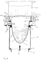
- a gas burner which is a housing-shaped prechamber 21 has.
- the pre-chamber 21 has an upper and a lower opening.
- the lower opening is surrounded by a flange 22 to which one Fuel gas supply line 23 can be flanged.
- a distributor plate in the flange connection 22 24 held clamped.
- a flange 14 of the prechamber 21 is rectangular turned inwards.
- a seal 12 can be placed on the flange 14 hang up.
- the seal 12 carries a mounting flange 15 of a molded body 10.
- the mounting plate 16 is screwed to the flange 14, so that the mounting flange 15 clamped between the two seals 12, 13 is held.
- An ignition system 17 can also be attached to the mounting plate 16 attach.
- the molded body 10 is designed as a hollow body. He has the cross section Geometry of a half ellipsoid. This ellipsoid is essentially of a coat 19 formed.
- the jacket 19 is connected to the mounting flange 14. It is provided with openings 11. As taken from the illustration the molded body 10 protrudes into the antechamber 21.
- a gas supply is not shown in the drawing Blower of a gas / air mixing device fuel gas into the fuel gas supply line 22 headed.
- the distributor plate 24 ensures that the fuel gas is even in the Antechamber 21 is distributed.
- the fuel gas flows through from the antechamber 21 the openings 11 in the molded body 10 into the combustion chamber 18.
- Fuel gas ignited Some flames are shown schematically in FIG. It is clear in this drawing that the complete combustion chamber 18 with Flames are filled. This creates turbulence and recirculation of the flames. This ensures that the incineration process Exhaust gas is burned in several stages. This will reduce the amount of carbon monoxide considerably reduced as an unburned residue product. Likewise lets enable a reduction in nitrogen oxides.
- the hollow body 10 is again schematically with its mounting flange 15 shown in perspective.
- the invention is but not limited solely to such geometries of a hollow body 10. Rather, it is conceivable that a partial spherical geometry is also used.
- 2b shows an example of the shape of a hemisphere.
- 3b shows a network of fibers that are resistant to high temperatures. Between The openings 11 are formed in the individual fibers. 3c shows a fleece-like, perforated braid made of high-temperature resistant fibers.
- Variants acc. 3b and 3c can be metallic or ceramic fibers for Come into play. However, ceramic fibers are preferably used subsequently coated with silicon carbite. Through the coating Silicon carbite hardens the braid or fleece. This is the shaped body 10 trained dimensionally stable, so that it is not a supportive constructive Measures needed. Furthermore, it is ensured that when handling the Shaped body 10 no distortion can occur, the geometry of the Affect breakthroughs 11.
- openings 11 show different possibilities for the design of openings 11.
- the clear opening area is not larger than 2.6 mm 2 .
- the opening area should not be less than 0.6 mm 2 . If, for example, openings 11 according to FIGS. 4d or 4e are selected, these can be arranged relatively closely to one another. This ensures that ignition of the fuel gas that flows out at an adjacent opening 11 is possible.
- FIG. 5 is a possible use of gas burners according to the invention shown in cooking appliances. It is a built-in cooking appliance with a housing 20 as the outer dimension. The housing is with a circumferential, outwardly projecting frame 32 connected. With this frame 32, the housing 20 in a recess of a worktop be hung up. Four gas burners are accommodated in the housing 20, of which the moldings 10 can be seen. Over or in the sneeze Gas burner has a cooking surface 26 mounted over the frame 32. At the cooktop 26 can be a glass ceramic cooktop. It is on the side provided with four openings in which controls 31 are inserted can. Further breakthroughs are present in the area above the molded body 10. These openings are covered by covers 27. The cover 27 form shelves for pots 30 and can also be designed as overflow protection.
- FIG. 6 is a partial section of a gas burner according to FIG. 5 in side view shown.
- the spacer elements 29 can be designed as individual bolts, webs or the like be.
- Exhaust ducts 27.2 are formed between the individual spacer elements. It is also conceivable to use a circumferential ring with the corresponding one Perforations allow exhaust gas transport.
- the cover 27 rests on the spacer elements 29.
- the cover 27 is designed as a flat plate, which on your. Edge with a circumferential, in Direction on the cooking surface 26 angled bevel 27.1 is provided.
- the cover 27 itself is preferably connected to spacer elements 29.
- Below the cooking surface 26 is a seal 28 with the interposition Flanged body 25 arranged.
- the seal 28 is made of an elastic Material is formed and comes on the underside of the cooking surface 26 directly below the spacer elements 29 to lie on.
- On the flange body 25 is the actual gas burner grown over the fasteners 16. The design this gas burner corresponds to the gas burner shown in FIG. 1. It is can be seen that the flange body 25 receives the ignition system 17 in its interior.
- the exhaust gases produced during combustion are made from the molded body 10 headed out towards the cover 27. Here they escape through the exhaust gas ducts 27.2 created between the spacer elements 29.
- the Slants 27.1 cause flow guidance and diversion, see above that a swirl of exhaust gas arises.
- the hot exhaust gases flow around it evenly the saucepan 30 and support its heating.
- the cooking surface 26 on the breakthrough surrounding edge with an edge with a raised wall.
- This wall can be a one-piece molding on the cooking surface 26. It is also conceivable to use an insert ring in the breakthrough is inserted.
Landscapes
- Engineering & Computer Science (AREA)
- Chemical & Material Sciences (AREA)
- Combustion & Propulsion (AREA)
- Mechanical Engineering (AREA)
- General Engineering & Computer Science (AREA)
- Gas Burners (AREA)
- Glass Compositions (AREA)
- Gas Separation By Absorption (AREA)
Abstract
Description
- Fig. 1
- in schematischer Seitendarstellung und im Schnitt einen Gasbrenner,
- Fig. 2a u. b
- zwei Ausführungsvarianten eines Formkörpers für den Gasbrenner gemäß Fig. 1,
- Fig. 3a bis 3c
- drei Varianten des Formkörpers gemäß Fig. 2a und
- Fig. 4a bis 4e
- ausschnittsweise verschiedene Bleche zur Ausbildung eines Formkörpers,
- Fig. 5
- in perspektivischer Darstellung eines Kochgerätes mit vier erfindungsgemäßen Gasbrennern und
- Fig. 6
- in Seitenansicht einen Schnitt durch einen, der in Fig. 5 gezeigten Gasbrenner.
Claims (9)
- Gasbrenner für Warmwasserbereiter, Heizsysteme oder dgl. mit einer Abbrenneinrichtung, der Brenngas zugeleitet ist, wobei die Abbrenneinrichtung einen mit Durchbrüchen versehenen Formkörper aufweist, und wobei die Durchbrüche eine räumliche Verbindung zwischen der Brenngasseite und der Brennseite herstellen,
dadurch gekennzeichnet,
daß der Formkörper (10) als offener Hohlkörper ausgebildet ist, der eine Brennkammer (18) umschließt. - Gasbrenner nach Anspruch 1,
dadurch gekennzeichnet,
daß der von dem Formkörper (10) umgebene Brennraum (18) die Form eines Teil-Ellipsoids oder einer Teil-Kugel hat, wobei die offene Seite des Teil-Ellipsoides oder der Teil-Kugel als Abgasaustritt dient. - Gasbrenner nach Anspruch 2,
dadurch gekennzeichnet,
daß die Durchbrüche (11) in dem Formkörper (10) vorzugsweise eine durchschnittliche Öffnungsfläche von 0,6 mm2 bis 2,6 mm2 aufweisen. - Gasbrenner nach einem der Ansprüche 1 bis 3,
dadurch gekennzeichnet,
daß zumindest der die Durchbrüche (11) aufweisende Teil des Formkörpers (10) aus einem gelochten Stahlblech gebildet ist. - Gasbrenner nach einem der Ansprüche 1 bis 3,
dadurch gekennzeichnet,
daß zumindest der die Durchbrüche (11) aufweisende Teil des Formkörpers (10) aus einem Werkstoff mit hochtemperaturbeständigen Fasern gebildet ist, die vlies- oder gewebeartig miteinander verbunden sind. - Gasbrenner nach einem der Ansprüche 1 bis 5,
dadurch gekennzeichnet,
daß der die Druchbrüche (11) aufweisenden Teil des Formkörpers (10) aus einem Sandventil-Aufbau aus Stahlblech (innen) und ein Faservliesgewebeteil besteht. - Gasbrenner nach einem der Ansprüche 1 bis 6,
dadurch gekennzeichnet,
daß an den Formkörper (10) ein nach außen gerichteter Befestigungsflansch (15) angeformt ist, mittels dem der Formkörper (10) an einer Vorkammer (21) befestigt ist, wobei der Formkörper (10) in die Vorkammer (21) ragt, und
daß an die Vorkammer (21) eine Brenngas-Zuleitung (23) angeschlossen ist. - Gasbrenner nach Anspruch 7,
dadurch gekennzeichnet,
daß zwischen der Brenngas-Zuleitung (23) und der Vorkammer (21) eine daß zwischen der Brenngas-Zuleitung (23) und der Vorkammer (21) eine Verteilerplatte (24) angeordnet ist. - Gasbrenner nach einem der Ansprüche 1 bis 8,
dadurch gekennzeichnet,
daß die größte lichte Weite im Inneren des Formkörpers (10) das Maß der doppelten maximalen Flammenlänge nicht übersteigt.
Applications Claiming Priority (2)
| Application Number | Priority Date | Filing Date | Title |
|---|---|---|---|
| DE19648808 | 1996-11-26 | ||
| DE19648808A DE19648808A1 (de) | 1996-11-26 | 1996-11-26 | Gasbrenner |
Publications (3)
| Publication Number | Publication Date |
|---|---|
| EP0852316A2 true EP0852316A2 (de) | 1998-07-08 |
| EP0852316A3 EP0852316A3 (de) | 1999-07-21 |
| EP0852316B1 EP0852316B1 (de) | 2003-06-25 |
Family
ID=7812722
Family Applications (1)
| Application Number | Title | Priority Date | Filing Date |
|---|---|---|---|
| EP97119993A Expired - Lifetime EP0852316B1 (de) | 1996-11-26 | 1997-11-14 | Gasbrenner |
Country Status (6)
| Country | Link |
|---|---|
| US (1) | US6129545A (de) |
| EP (1) | EP0852316B1 (de) |
| JP (1) | JP3936045B2 (de) |
| AT (1) | ATE243829T1 (de) |
| DE (2) | DE19648808A1 (de) |
| PL (1) | PL323340A1 (de) |
Cited By (1)
| Publication number | Priority date | Publication date | Assignee | Title |
|---|---|---|---|---|
| EP4006417A1 (de) * | 2020-11-30 | 2022-06-01 | Beckett Thermal Solutions S.R.L. | Brennermembran für einen brenner |
Families Citing this family (28)
| Publication number | Priority date | Publication date | Assignee | Title |
|---|---|---|---|---|
| DE19847042B4 (de) * | 1998-10-13 | 2008-05-29 | Ceramat, S. Coop., Asteasu | Hochporöse Brennermatte für Gas- und/oder Ölbrenner |
| FR2801372B1 (fr) * | 1999-11-24 | 2002-02-15 | Eurokera | Plaque de cuisson |
| DE10048500C2 (de) * | 2000-10-07 | 2003-04-30 | Horst Ley | Gasbrenner zur industriellen Verwendung |
| WO2002093075A1 (fr) * | 2001-05-14 | 2002-11-21 | Vladimir Mikhailovich Shmelev | Bruleur fonctionnant par rayonnement |
| FR2835042B1 (fr) * | 2002-01-22 | 2004-12-17 | Mer Joseph Le | Bruleur a gaz, a face de combustion bipartite et chaudiere equipee d'un tel bruleur |
| ITMI20022081A1 (it) * | 2002-10-02 | 2004-04-03 | Tecnoclima Spa | Generatore d'aria calda. |
| FR2848642B1 (fr) * | 2002-12-17 | 2005-08-05 | Service Nat Dit Gaz De France | Bruleur a gaz a flamme interne, de compacite elevee |
| JP2008039283A (ja) * | 2006-08-07 | 2008-02-21 | Dainichi Co Ltd | 燃焼装置 |
| US8591222B2 (en) * | 2009-10-30 | 2013-11-26 | Trane International, Inc. | Gas-fired furnace with cavity burners |
| DE102010021997B4 (de) * | 2010-05-29 | 2018-12-20 | Robert Bosch Gmbh | Gasbrenner für ein Heizgerät |
| NL2005105C2 (en) * | 2010-07-19 | 2012-01-23 | Intell Properties B V | Gas hob with inside burner. |
| ITMI20102001A1 (it) * | 2010-10-27 | 2012-04-28 | Worgas Bruciatori Srl | Bruciatore cavo a combustione interna |
| ITPD20120282A1 (it) | 2012-09-27 | 2014-03-28 | Systema Polska Sp Zo O | Testa di combustione a gas per bruciatori premiscelati |
| US9464805B2 (en) * | 2013-01-16 | 2016-10-11 | Lochinvar, Llc | Modulating burner |
| US10119704B2 (en) | 2013-02-14 | 2018-11-06 | Clearsign Combustion Corporation | Burner system including a non-planar perforated flame holder |
| US11953201B2 (en) | 2013-02-14 | 2024-04-09 | Clearsign Technologies Corporation | Control system and method for a burner with a distal flame holder |
| GB2512894A (en) * | 2013-04-10 | 2014-10-15 | David Thomas Bell | Inward firing multiple zoned gas burner |
| DE102014209529A1 (de) * | 2014-05-20 | 2015-11-26 | Siemens Aktiengesellschaft | Verbrennung von Lithium bei unterschiedlichen Temperaturen, Drücken und Gasüberschüssen mit porösen Rohren als Brenner |
| WO2016134061A1 (en) | 2015-02-17 | 2016-08-25 | Clearsign Combustion Corporation | Perforated flame holder with adjustable fuel nozzle |
| US20160238242A1 (en) * | 2015-02-18 | 2016-08-18 | Clearsign Combustion Corporation | Burner with a perforated flame holder support structure |
| CN112432166B (zh) | 2016-01-13 | 2023-10-27 | 美一蓝技术公司 | 瓷砖组之间具有间隙的穿孔火焰保持器 |
| WO2017190080A1 (en) | 2016-04-29 | 2017-11-02 | Clearsign Combustion Corporation | Burner system with discrete transverse flame stabilizers |
| US10539326B2 (en) | 2016-09-07 | 2020-01-21 | Clearsign Combustion Corporation | Duplex burner with velocity-compensated mesh and thickness |
| WO2018085152A1 (en) | 2016-11-04 | 2018-05-11 | Clearsign Combustion Corporation | Plasma pilot |
| CN110199153B (zh) | 2017-03-02 | 2021-09-03 | 美一蓝技术公司 | 具有穿孔火焰保持器和涡流稳定的预热火焰的燃烧系统 |
| CN106969354A (zh) * | 2017-04-03 | 2017-07-21 | 山东宇丰商用厨具有限公司 | 一种用于煲仔饭烹饪的炉头 |
| JP6834772B2 (ja) * | 2017-05-22 | 2021-02-24 | 株式会社ノーリツ | 温水装置 |
| KR102428535B1 (ko) * | 2017-12-29 | 2022-08-03 | 주식회사 경동나비엔 | 연관식 보일러 |
Citations (2)
| Publication number | Priority date | Publication date | Assignee | Title |
|---|---|---|---|---|
| US4657506A (en) | 1984-12-10 | 1987-04-14 | Glowcore Corporation | Gas burner |
| US5165887A (en) | 1991-09-23 | 1992-11-24 | Solaronics | Burner element of woven ceramic fiber, and infrared heater for fluid immersion apparatus including the same |
Family Cites Families (14)
| Publication number | Priority date | Publication date | Assignee | Title |
|---|---|---|---|---|
| US3527199A (en) * | 1968-04-19 | 1970-09-08 | American Gas Ass | Gas burner apparatus |
| US3525325A (en) * | 1968-05-03 | 1970-08-25 | Tappan Co The | High pressure gas burner |
| NL7314826A (de) * | 1972-12-11 | 1974-06-13 | ||
| US3857670A (en) * | 1973-03-29 | 1974-12-31 | Int Magna Corp | Radiant burner |
| US4039275A (en) * | 1976-02-23 | 1977-08-02 | Mcgettrick Charles A | Infrared energy generator with orifice plate |
| US4157155A (en) * | 1976-04-07 | 1979-06-05 | Smith Thomas M | Sealing apparatus and method |
| US4397631A (en) * | 1980-09-08 | 1983-08-09 | The Carlin Company | Pre-mix forced draft power gas burner |
| JPS5824715A (ja) * | 1981-08-06 | 1983-02-14 | Matsushita Electric Ind Co Ltd | ガス燃焼装置 |
| US5356487A (en) * | 1983-07-25 | 1994-10-18 | Quantum Group, Inc. | Thermally amplified and stimulated emission radiator fiber matrix burner |
| ATE174681T1 (de) * | 1992-03-03 | 1999-01-15 | Bekaert Sa Nv | Poröse metallfiber-platte |
| EP0579315A1 (de) * | 1992-07-07 | 1994-01-19 | Ingenieursburo P.I. Produkt Innovatie B.V. | Brenner |
| DE4310891C1 (de) * | 1993-03-18 | 1994-10-20 | Cramer Gmbh & Co Kg | Brennkammer mit Gasstrahlungsbrenner für Kessel zur Erwärmung von Heizwasser und/oder Brauchwasser, insbesondere für Haushalte |
| US5406703A (en) * | 1993-10-12 | 1995-04-18 | Greene Manufacturing Company | Method of making a tube burner for cooking apparatus |
| US5458484A (en) * | 1994-05-16 | 1995-10-17 | Carrier Corporation | Pre-mix flame type burner |
-
1996
- 1996-11-26 DE DE19648808A patent/DE19648808A1/de not_active Ceased
-
1997
- 1997-11-14 AT AT97119993T patent/ATE243829T1/de not_active IP Right Cessation
- 1997-11-14 DE DE59710342T patent/DE59710342D1/de not_active Expired - Fee Related
- 1997-11-14 EP EP97119993A patent/EP0852316B1/de not_active Expired - Lifetime
- 1997-11-26 PL PL97323340A patent/PL323340A1/xx unknown
- 1997-11-26 US US08/979,532 patent/US6129545A/en not_active Expired - Fee Related
- 1997-11-26 JP JP32492597A patent/JP3936045B2/ja not_active Expired - Fee Related
Patent Citations (2)
| Publication number | Priority date | Publication date | Assignee | Title |
|---|---|---|---|---|
| US4657506A (en) | 1984-12-10 | 1987-04-14 | Glowcore Corporation | Gas burner |
| US5165887A (en) | 1991-09-23 | 1992-11-24 | Solaronics | Burner element of woven ceramic fiber, and infrared heater for fluid immersion apparatus including the same |
Cited By (2)
| Publication number | Priority date | Publication date | Assignee | Title |
|---|---|---|---|---|
| EP4006417A1 (de) * | 2020-11-30 | 2022-06-01 | Beckett Thermal Solutions S.R.L. | Brennermembran für einen brenner |
| US12352435B2 (en) | 2020-11-30 | 2025-07-08 | Beckett Thermal Solutions S.R.L. | Combustion membrane for a gas burner |
Also Published As
| Publication number | Publication date |
|---|---|
| ATE243829T1 (de) | 2003-07-15 |
| DE59710342D1 (de) | 2003-07-31 |
| EP0852316A3 (de) | 1999-07-21 |
| PL323340A1 (en) | 1998-06-08 |
| JP3936045B2 (ja) | 2007-06-27 |
| US6129545A (en) | 2000-10-10 |
| DE19648808A1 (de) | 1998-06-04 |
| JPH10160128A (ja) | 1998-06-19 |
| EP0852316B1 (de) | 2003-06-25 |
Similar Documents
| Publication | Publication Date | Title |
|---|---|---|
| EP0852316B1 (de) | Gasbrenner | |
| EP2467642B1 (de) | Strahlungsbrenner | |
| DE4326945C2 (de) | Regeleinrichtung für die Gaszufuhr zu einer Gaskocheinrichtung mit unter einer durchgehenden Kochfläche angeordneten Gasstrahlungsbrennern | |
| DE2440701C3 (de) | Gasherd mit mehreren Kochstellen-Brennern | |
| EP0778449A1 (de) | Modular aufgebaute Kochfeldanordnung unter einer Glaskeramik-Kochfläche | |
| EP1134499B1 (de) | Kochfeld | |
| DE6912153U (de) | Backofen | |
| EP1523641B1 (de) | Porenbrenner sowie gargerät, enthaltend mindestens einen porenbrenner | |
| EP0626539A2 (de) | Mit Gas betriebener Infrarotstrahler für Heizzwecke | |
| DE69206501T2 (de) | Infrarotstrahlungsbrenner für Glaskeramik-Kochmulde. | |
| EP3479022B1 (de) | Gasbrenner und haushaltsgargerät | |
| DE19605649A1 (de) | Gasbrenner für Herde | |
| DE19725895A1 (de) | Infrarot-Gasbrenner für Gasherde | |
| DE19844551C2 (de) | Gaskochgerät | |
| DE2721921B2 (de) | Gas-Kocheinrichtung mit einer gasdichten Abdeckplatte | |
| DE10041472C1 (de) | Gasstrahlungsbrenner | |
| DE2337517A1 (de) | Gasbeheizter wassererhitzer | |
| DE19718885A1 (de) | Gasbrenner | |
| AT401192B (de) | Brenner für ein gas-luft-gemisch | |
| DE102013102885A1 (de) | Gargerät | |
| CH399697A (de) | Strahlungsbrenner | |
| DE69514916T2 (de) | Brennerkopf insbesondere für Gasbrenner | |
| DE69802936T2 (de) | Heizgerät | |
| DE69102952T2 (de) | Heizapparat mit katalytischer Verbrennung. | |
| EP0305962A2 (de) | Gasflammen-Hitzeverteiler für Kochgeschirr und/oder Kochplatte |
Legal Events
| Date | Code | Title | Description |
|---|---|---|---|
| PUAI | Public reference made under article 153(3) epc to a published international application that has entered the european phase |
Free format text: ORIGINAL CODE: 0009012 |
|
| AK | Designated contracting states |
Kind code of ref document: A2 Designated state(s): AT DE ES FR GB IT NL |
|
| AX | Request for extension of the european patent |
Free format text: AL;LT;LV;MK;RO;SI |
|
| PUAL | Search report despatched |
Free format text: ORIGINAL CODE: 0009013 |
|
| AK | Designated contracting states |
Kind code of ref document: A3 Designated state(s): AT BE CH DE DK ES FI FR GB GR IE IT LI LU MC NL PT SE |
|
| AX | Request for extension of the european patent |
Free format text: AL;LT;LV;MK;RO;SI |
|
| 17P | Request for examination filed |
Effective date: 20000121 |
|
| AKX | Designation fees paid |
Free format text: AT DE ES FR GB IT NL |
|
| 17Q | First examination report despatched |
Effective date: 20000921 |
|
| GRAH | Despatch of communication of intention to grant a patent |
Free format text: ORIGINAL CODE: EPIDOS IGRA |
|
| GRAH | Despatch of communication of intention to grant a patent |
Free format text: ORIGINAL CODE: EPIDOS IGRA |
|
| GRAA | (expected) grant |
Free format text: ORIGINAL CODE: 0009210 |
|
| AK | Designated contracting states |
Designated state(s): AT DE ES FR GB IT NL |
|
| PG25 | Lapsed in a contracting state [announced via postgrant information from national office to epo] |
Ref country code: FR Free format text: LAPSE BECAUSE OF FAILURE TO SUBMIT A TRANSLATION OF THE DESCRIPTION OR TO PAY THE FEE WITHIN THE PRESCRIBED TIME-LIMIT Effective date: 20030625 |
|
| REG | Reference to a national code |
Ref country code: GB Ref legal event code: FG4D Free format text: NOT ENGLISH |
|
| REF | Corresponds to: |
Ref document number: 59710342 Country of ref document: DE Date of ref document: 20030731 Kind code of ref document: P |
|
| GBT | Gb: translation of ep patent filed (gb section 77(6)(a)/1977) | ||
| PG25 | Lapsed in a contracting state [announced via postgrant information from national office to epo] |
Ref country code: AT Free format text: LAPSE BECAUSE OF NON-PAYMENT OF DUE FEES Effective date: 20031114 |
|
| PG25 | Lapsed in a contracting state [announced via postgrant information from national office to epo] |
Ref country code: ES Free format text: LAPSE BECAUSE OF FAILURE TO SUBMIT A TRANSLATION OF THE DESCRIPTION OR TO PAY THE FEE WITHIN THE PRESCRIBED TIME-LIMIT Effective date: 20031222 |
|
| PLBE | No opposition filed within time limit |
Free format text: ORIGINAL CODE: 0009261 |
|
| STAA | Information on the status of an ep patent application or granted ep patent |
Free format text: STATUS: NO OPPOSITION FILED WITHIN TIME LIMIT |
|
| 26N | No opposition filed |
Effective date: 20040326 |
|
| EN | Fr: translation not filed | ||
| REG | Reference to a national code |
Ref country code: GB Ref legal event code: 732E |
|
| NLS | Nl: assignments of ep-patents |
Owner name: SCHOTT AG Effective date: 20060612 |
|
| REG | Reference to a national code |
Ref country code: GB Ref legal event code: 732E |
|
| NLS | Nl: assignments of ep-patents |
Owner name: CERAMAT, S.COOP. Effective date: 20070605 |
|
| PGFP | Annual fee paid to national office [announced via postgrant information from national office to epo] |
Ref country code: NL Payment date: 20081113 Year of fee payment: 12 Ref country code: DE Payment date: 20081121 Year of fee payment: 12 |
|
| PGFP | Annual fee paid to national office [announced via postgrant information from national office to epo] |
Ref country code: IT Payment date: 20081125 Year of fee payment: 12 |
|
| PGFP | Annual fee paid to national office [announced via postgrant information from national office to epo] |
Ref country code: GB Payment date: 20081117 Year of fee payment: 12 |
|
| REG | Reference to a national code |
Ref country code: NL Ref legal event code: V1 Effective date: 20100601 |
|
| GBPC | Gb: european patent ceased through non-payment of renewal fee |
Effective date: 20091114 |
|
| PG25 | Lapsed in a contracting state [announced via postgrant information from national office to epo] |
Ref country code: NL Free format text: LAPSE BECAUSE OF NON-PAYMENT OF DUE FEES Effective date: 20100601 |
|
| PG25 | Lapsed in a contracting state [announced via postgrant information from national office to epo] |
Ref country code: DE Free format text: LAPSE BECAUSE OF NON-PAYMENT OF DUE FEES Effective date: 20100601 |
|
| PG25 | Lapsed in a contracting state [announced via postgrant information from national office to epo] |
Ref country code: GB Free format text: LAPSE BECAUSE OF NON-PAYMENT OF DUE FEES Effective date: 20091114 |
|
| PG25 | Lapsed in a contracting state [announced via postgrant information from national office to epo] |
Ref country code: IT Free format text: LAPSE BECAUSE OF NON-PAYMENT OF DUE FEES Effective date: 20091114 |